Here is the finished product:
And here is another quick video of the testing:
Here are the files on Thingiverse: https://www.thingiverse.com/thing:4428184
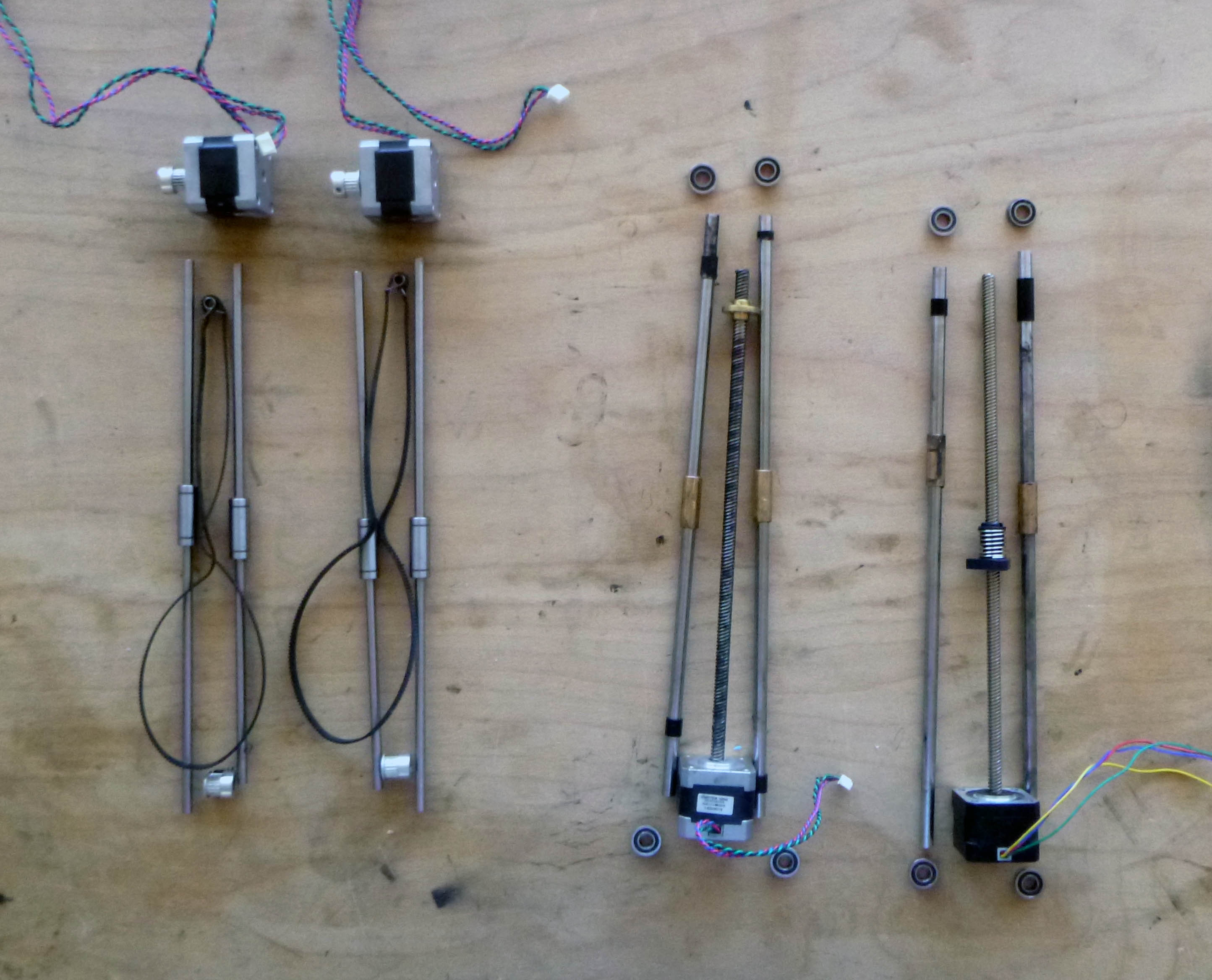
We’ll be harvesting parts from an old Ultimaker 2.
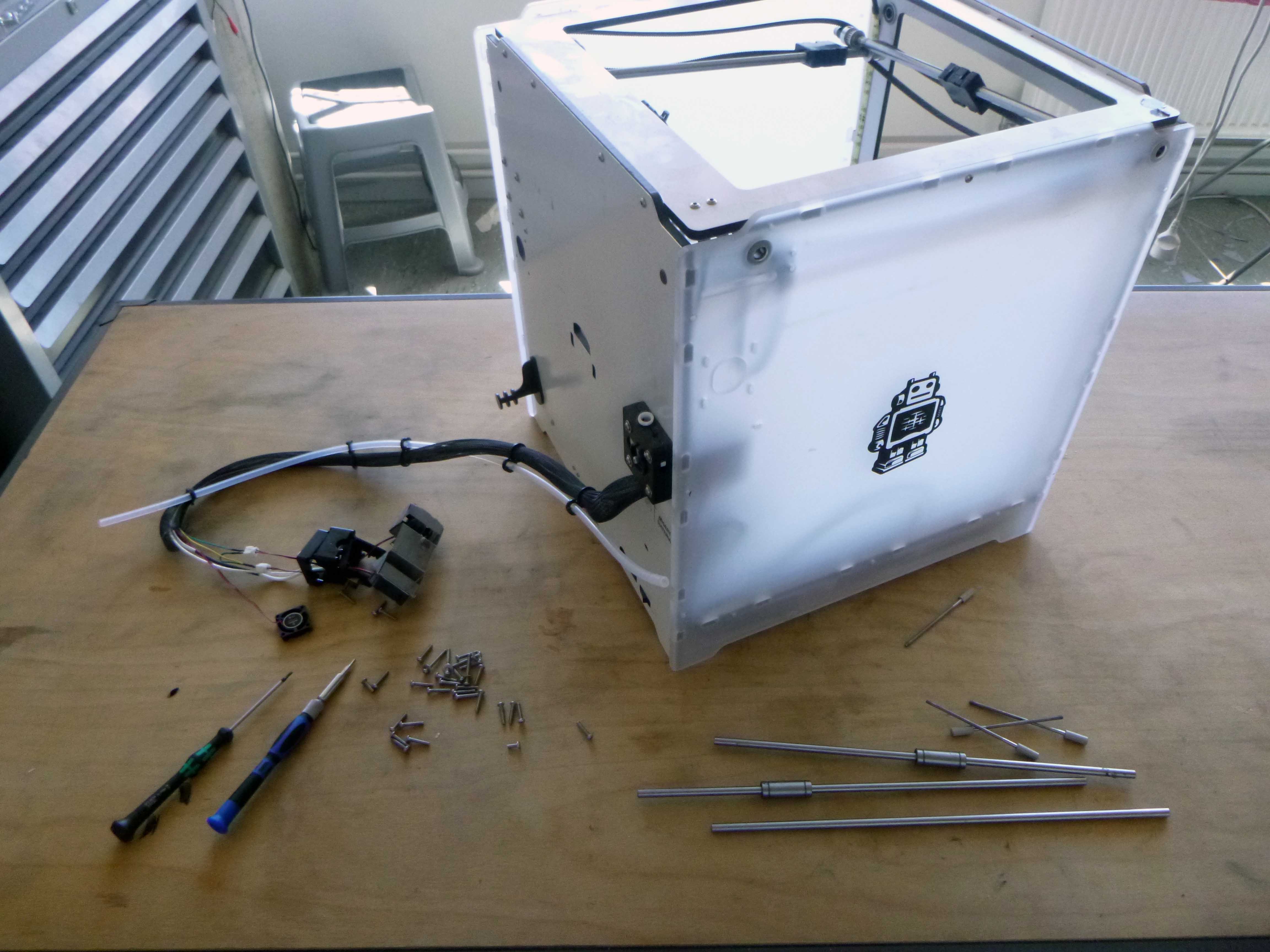
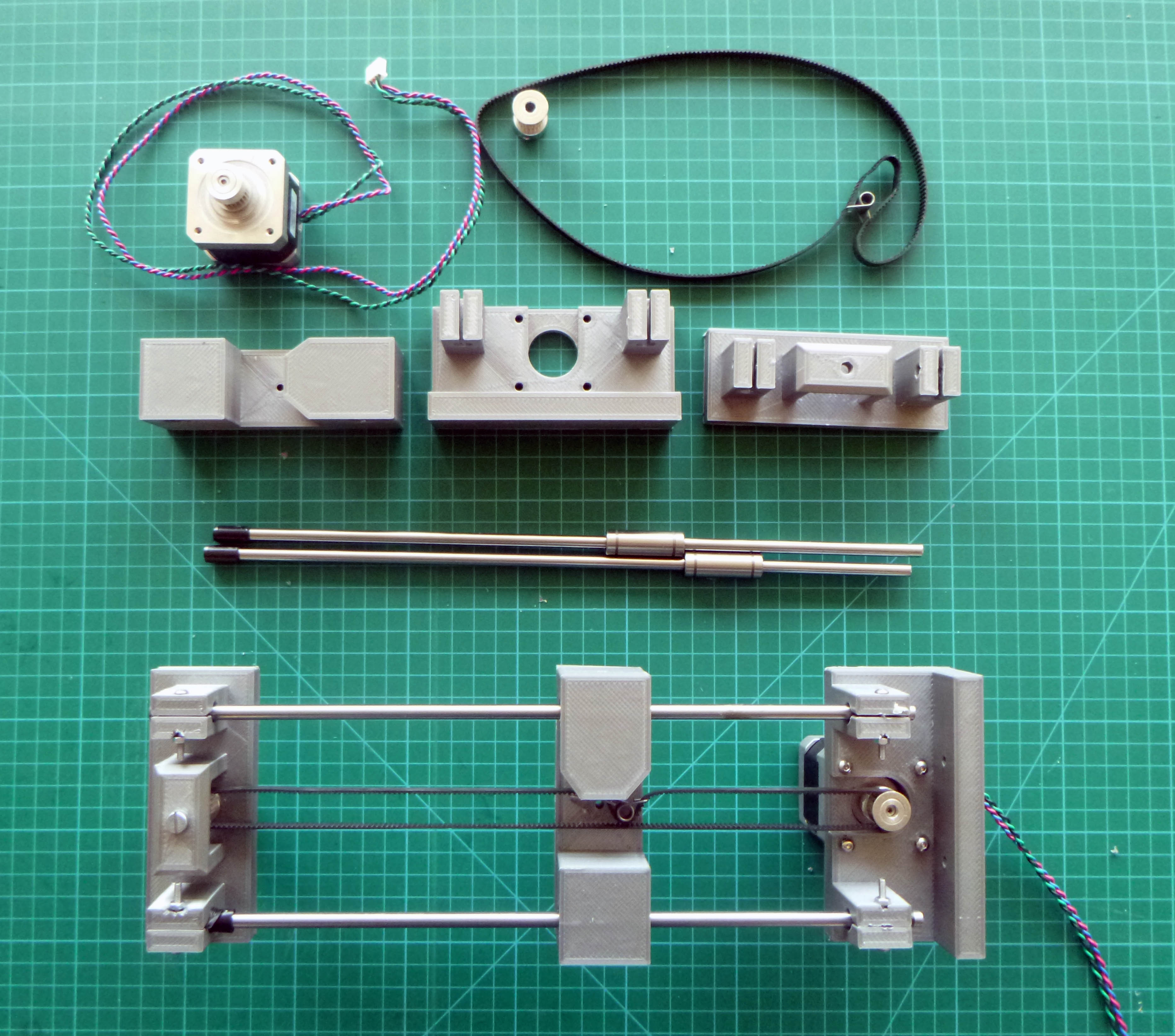
The stuff we plan to use:
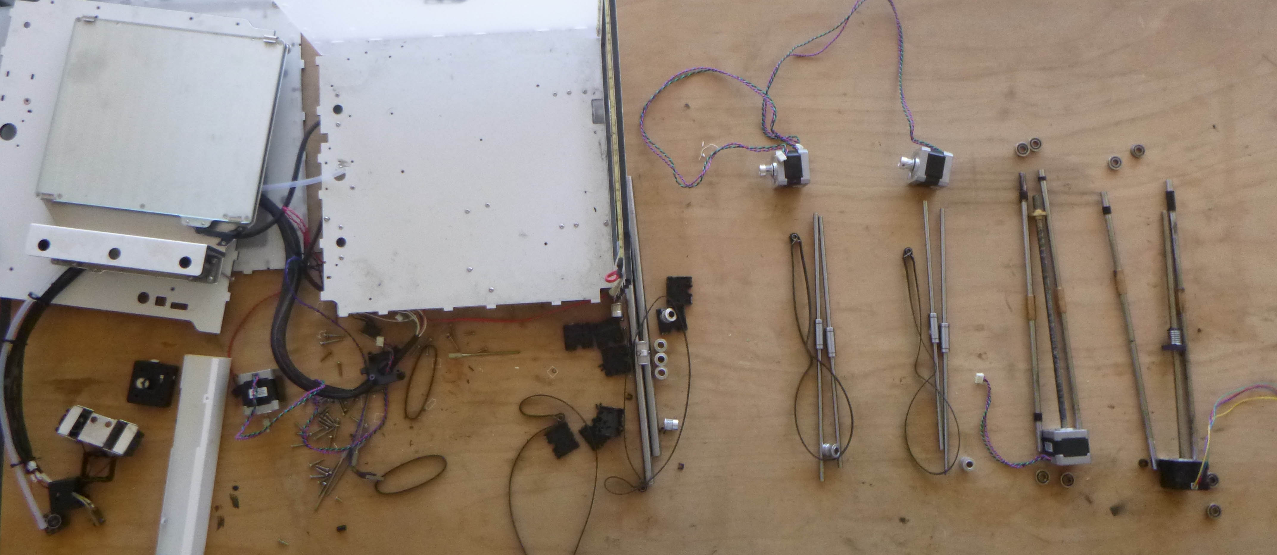
Based on what we found, we plan on making two threaded rod actuators and two belt-driven actuators.
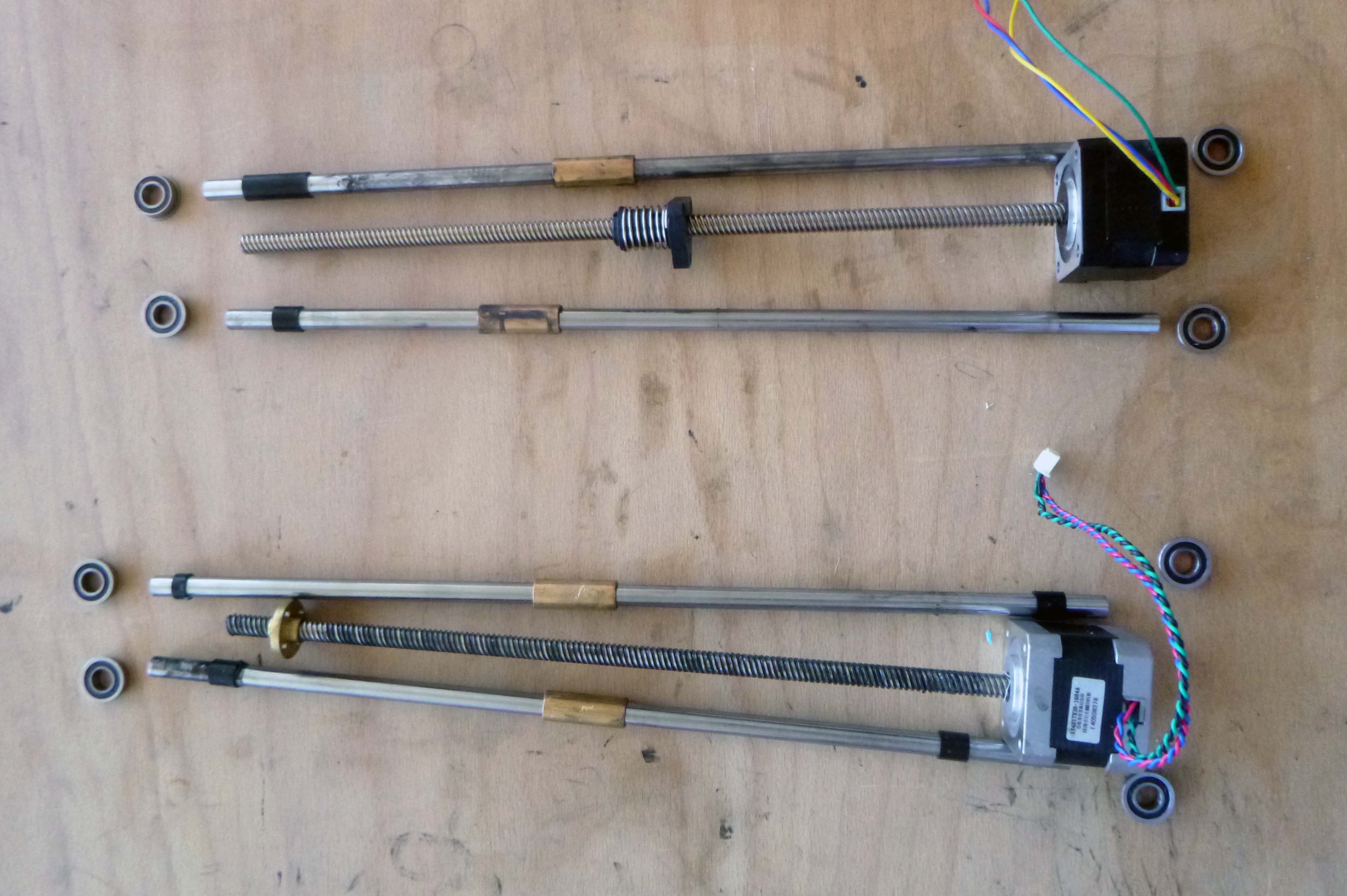
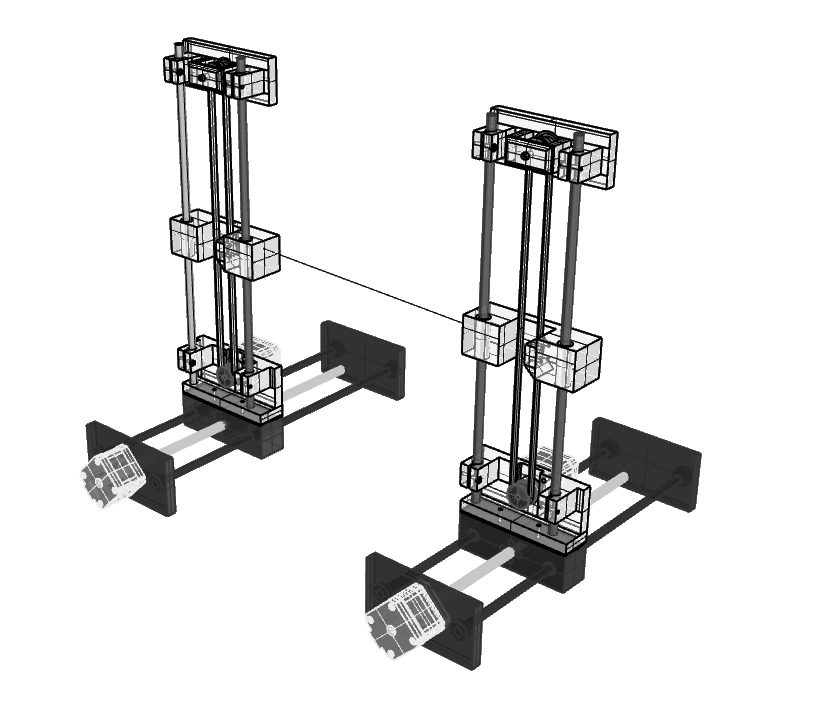
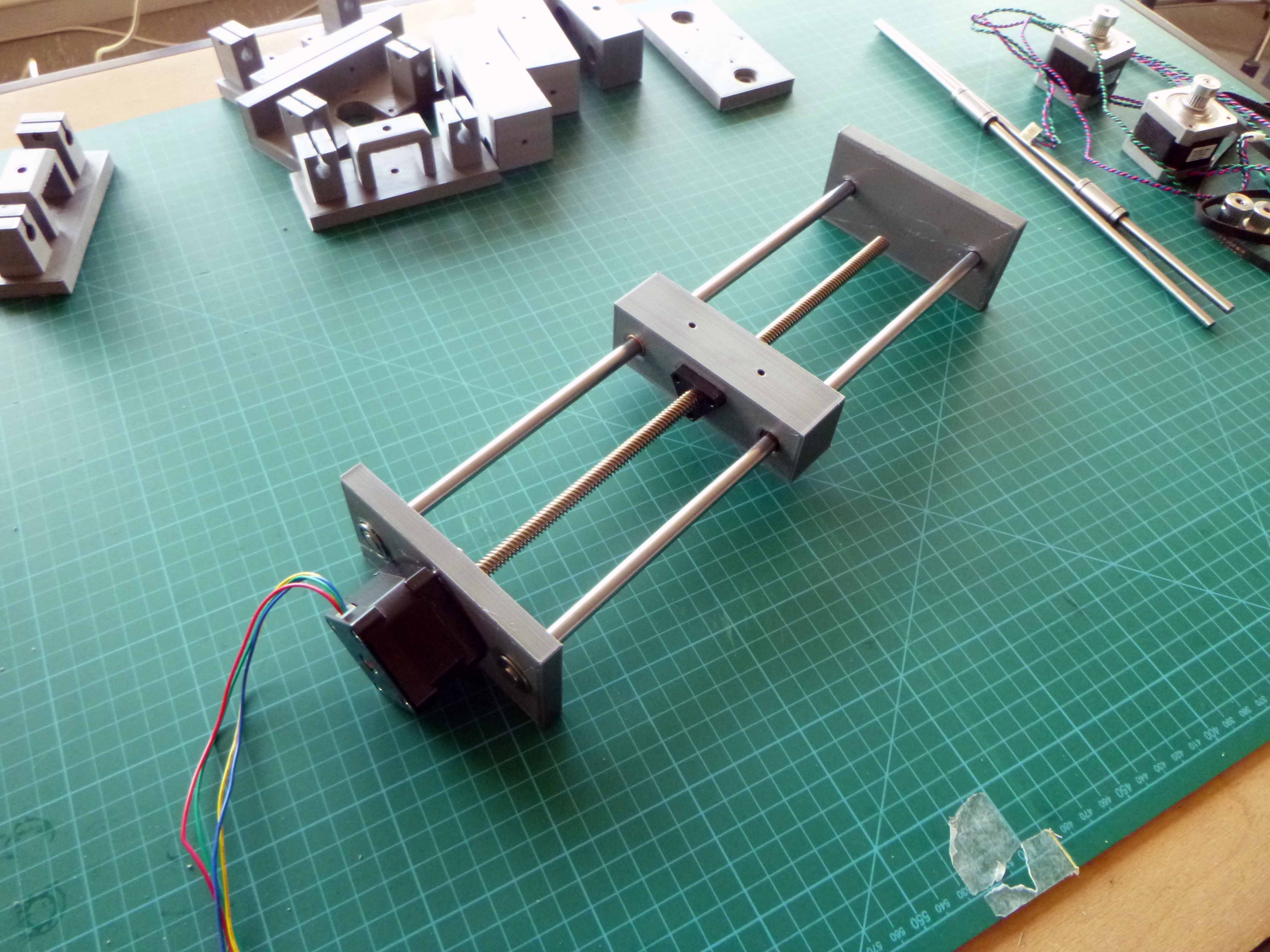
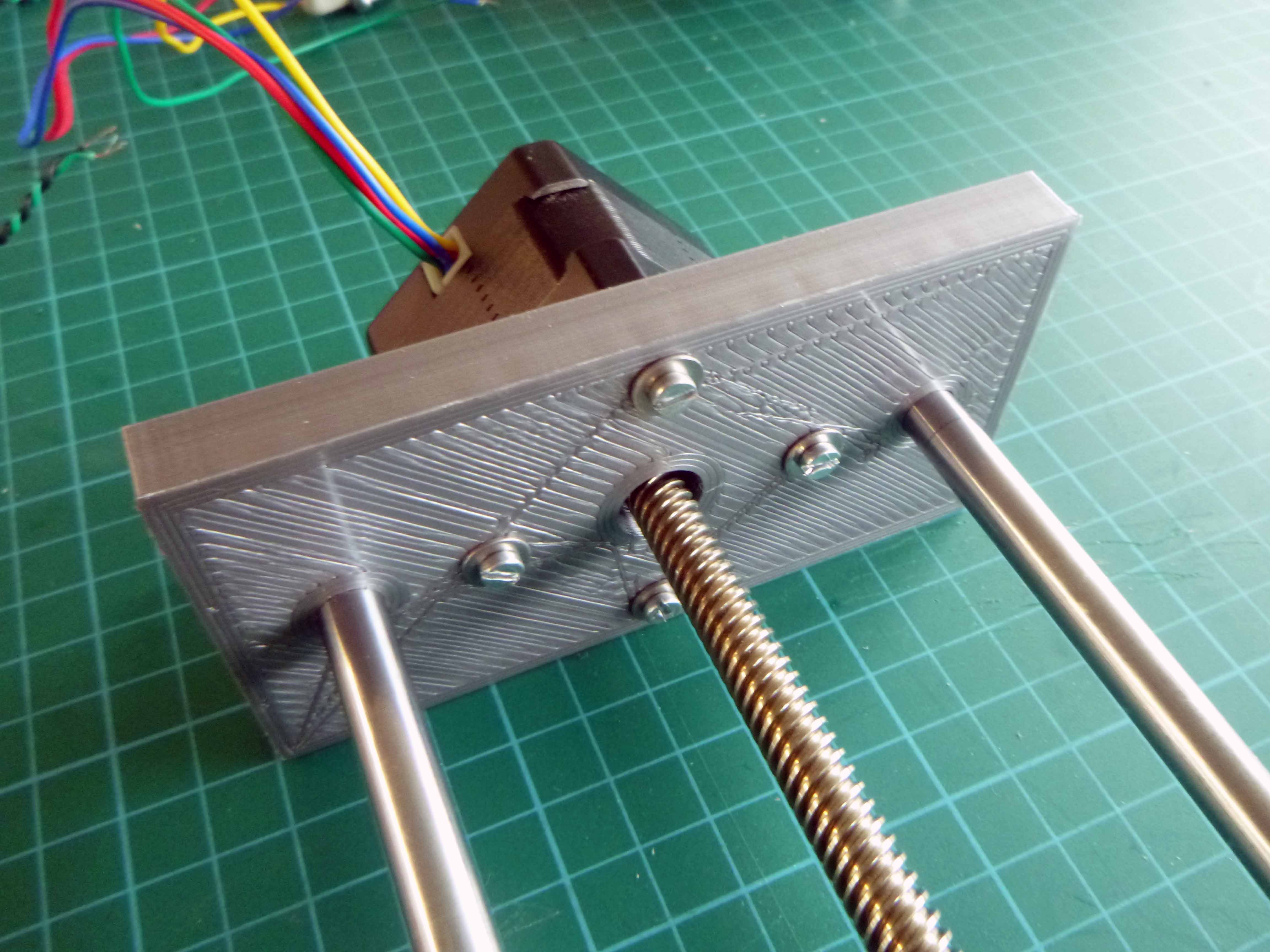
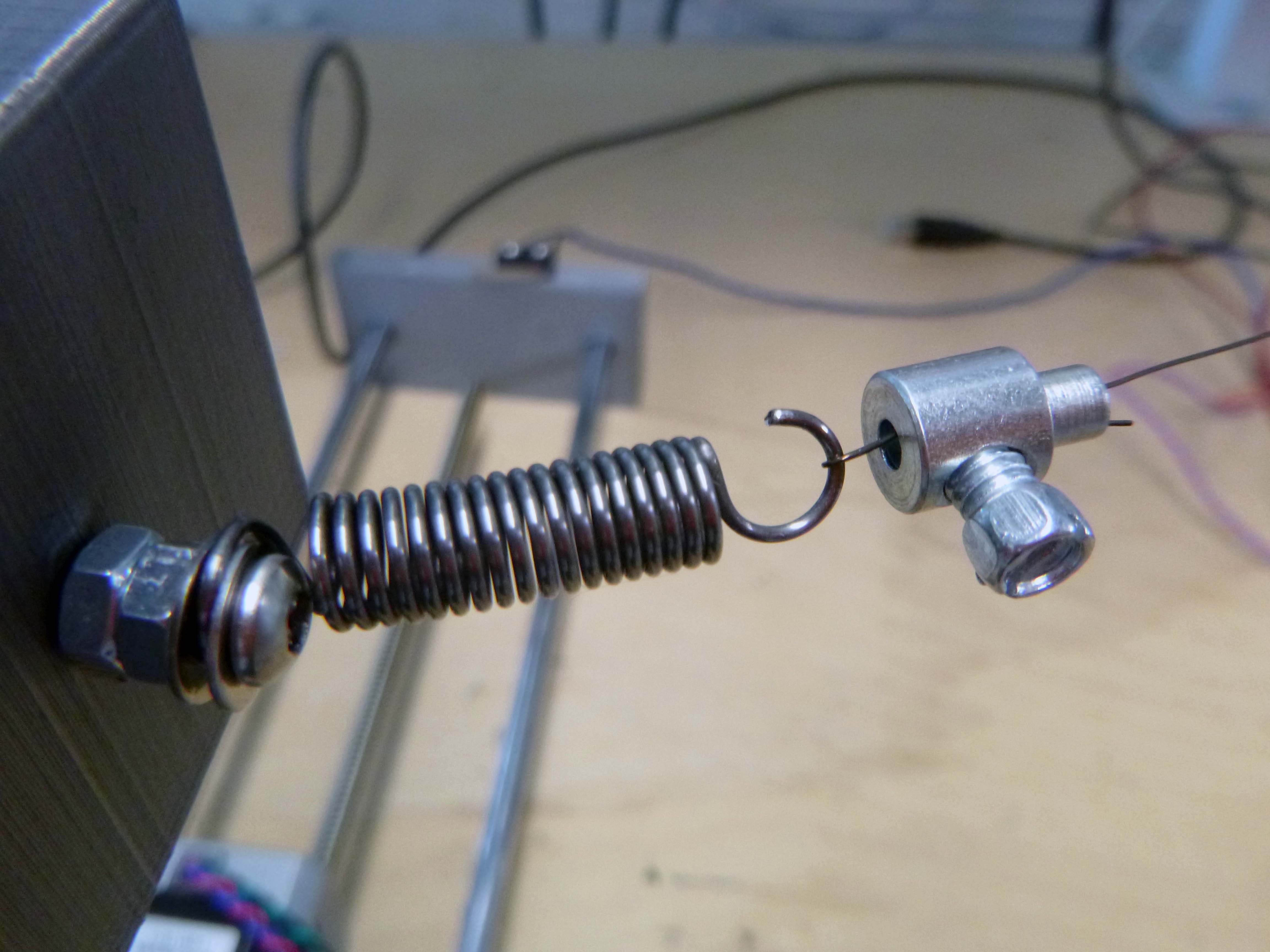
Here is the prototype of the linear threaded rod actuator:
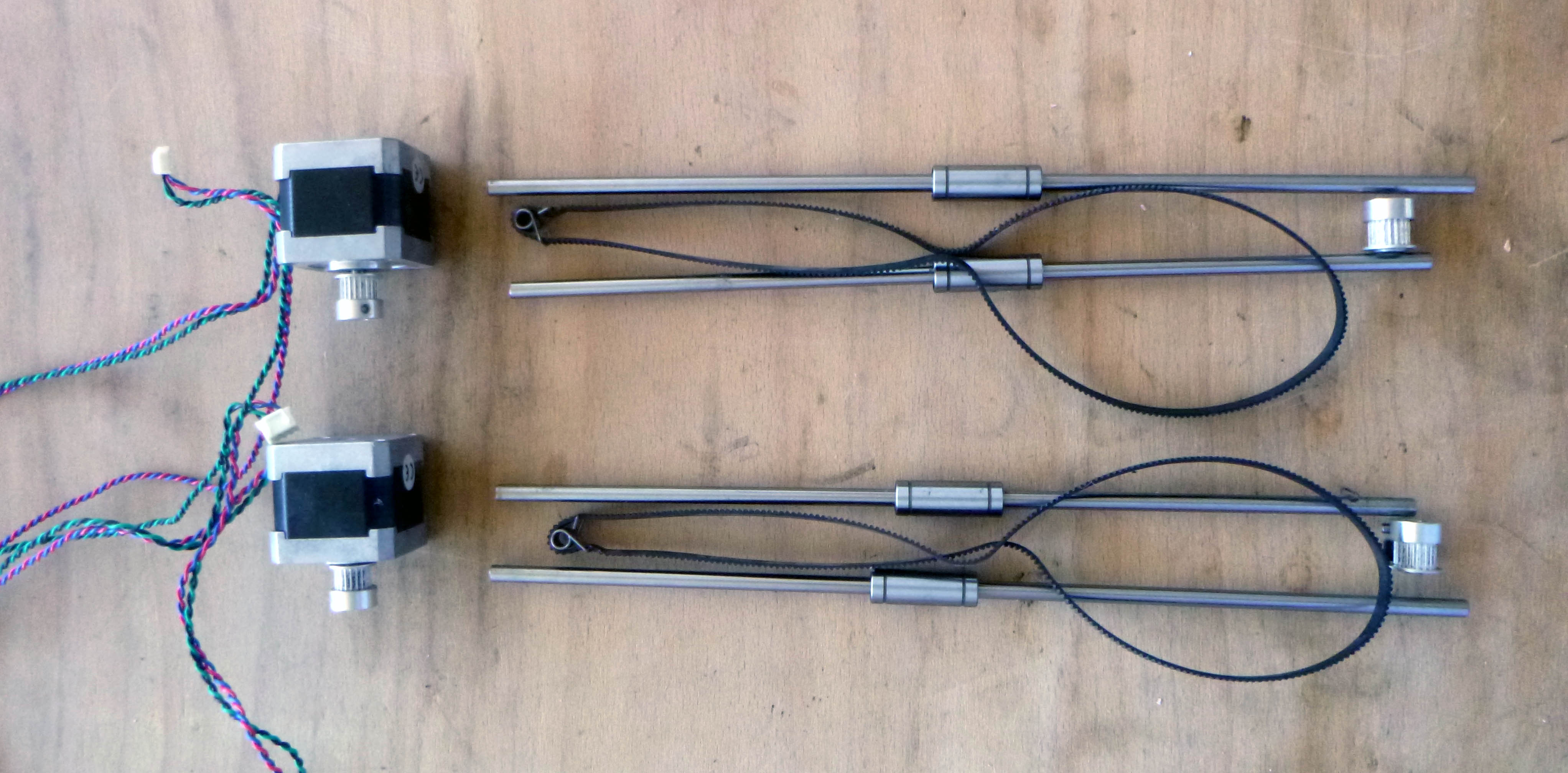
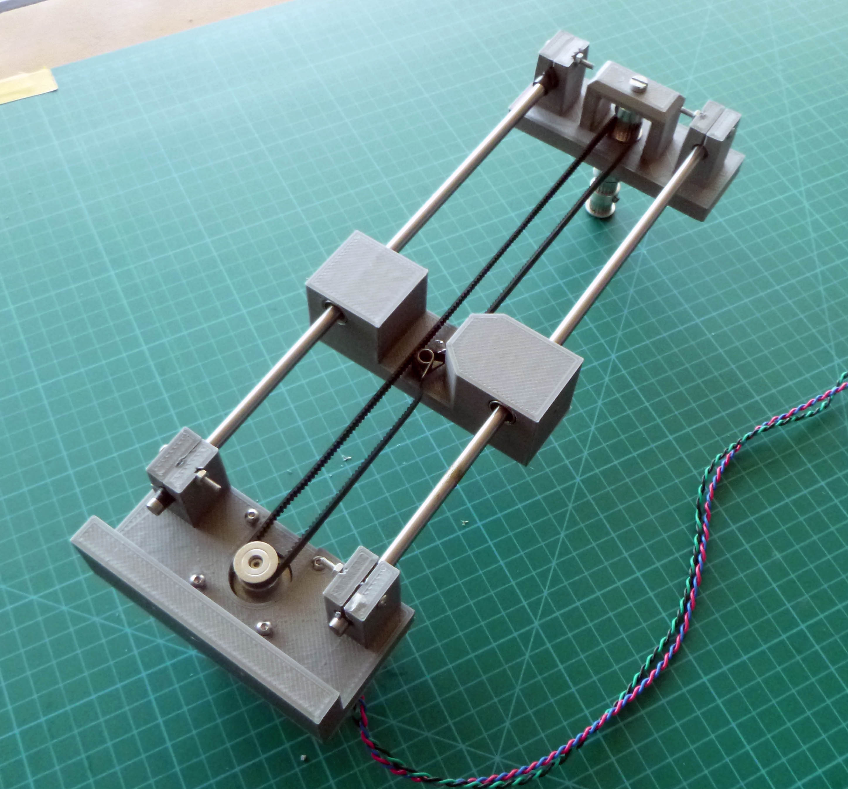
Here is the prototype of the linear belt-driven actuator:
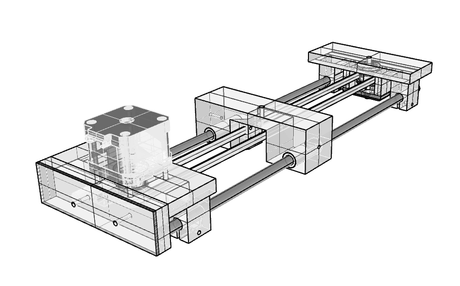
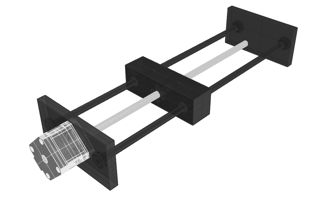
Here is the prototype of the entire foam cutter assembly:
Here are all the parts 3D printed: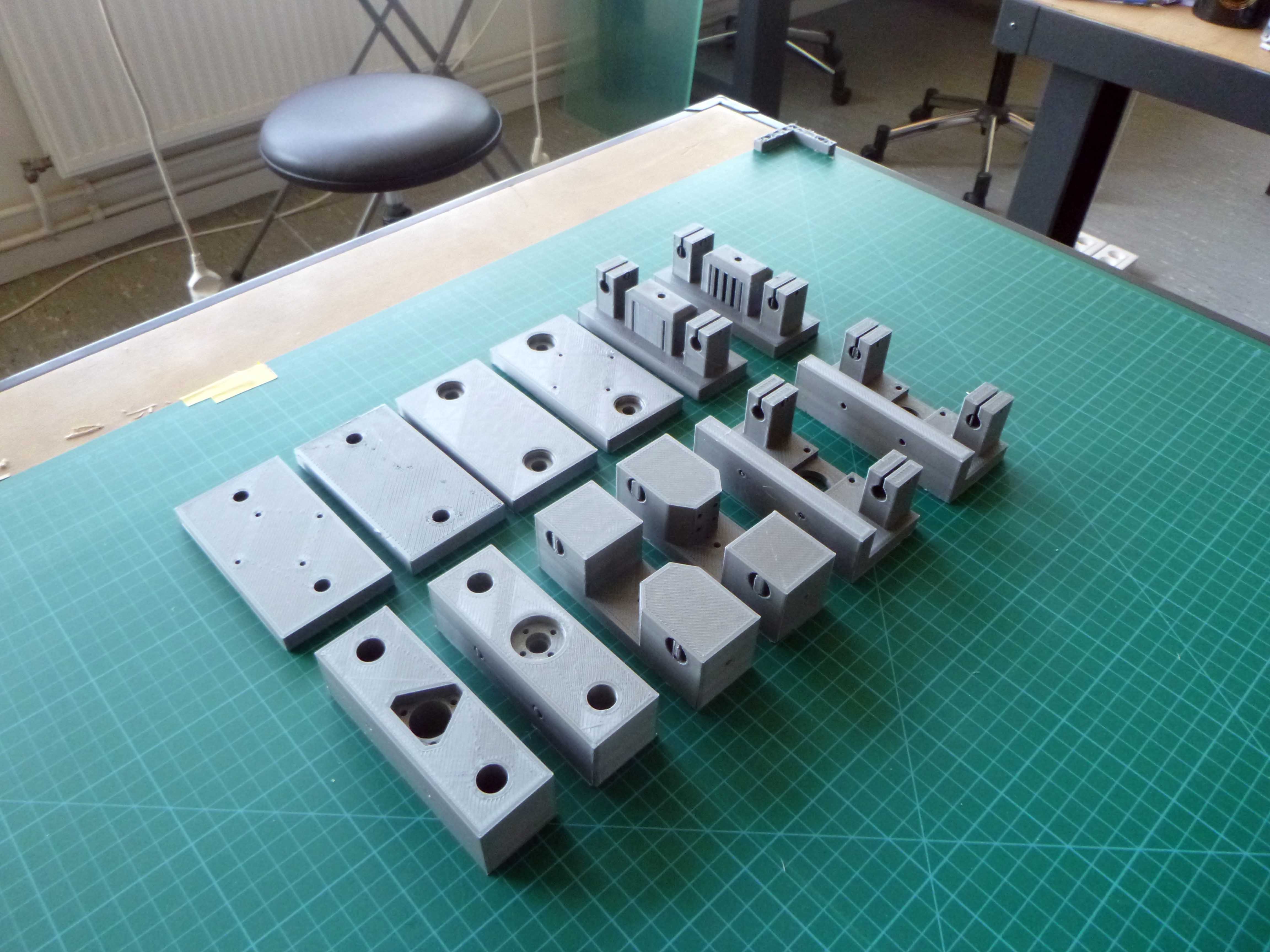
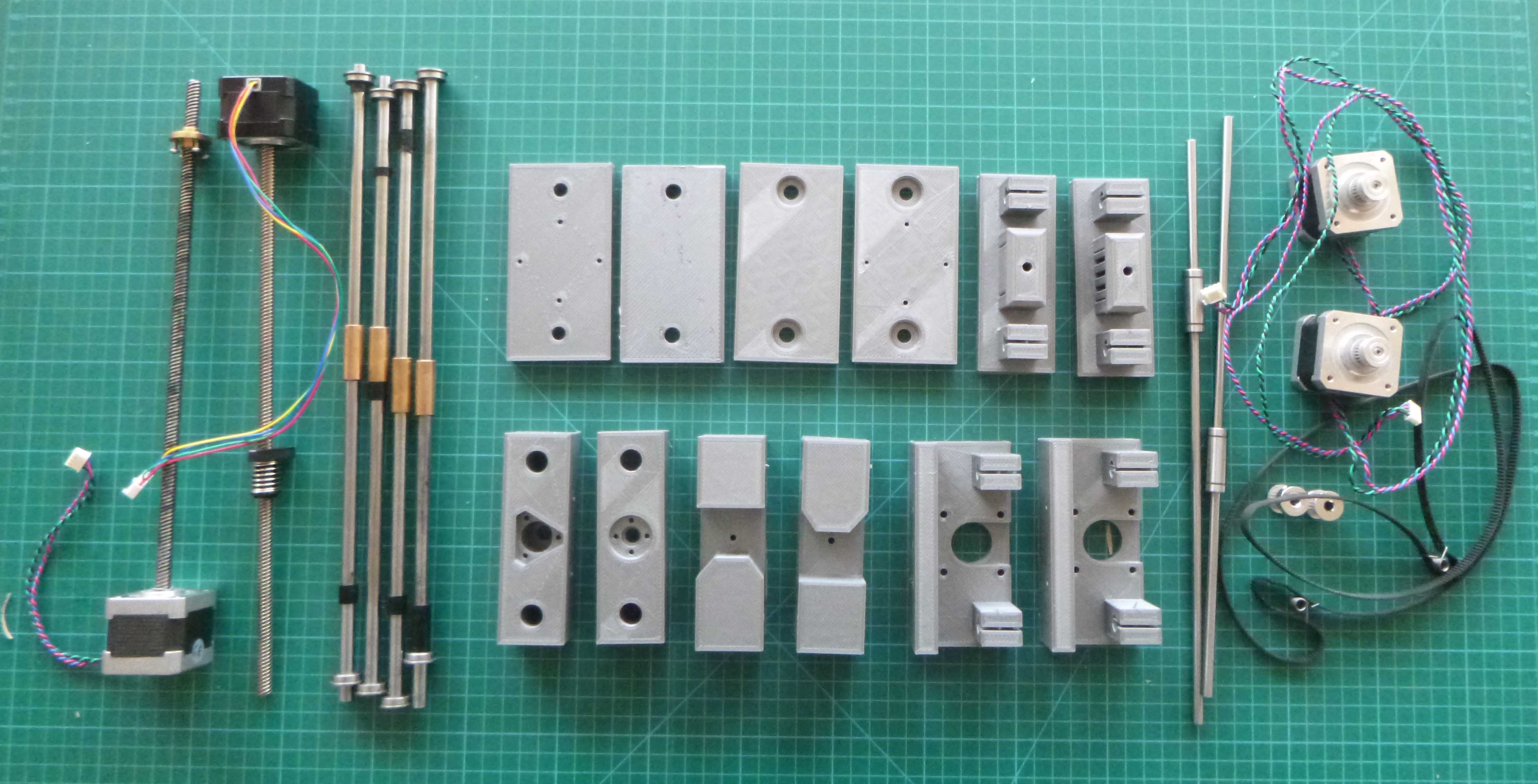
Here are the 3D printed parts along with the hardware:
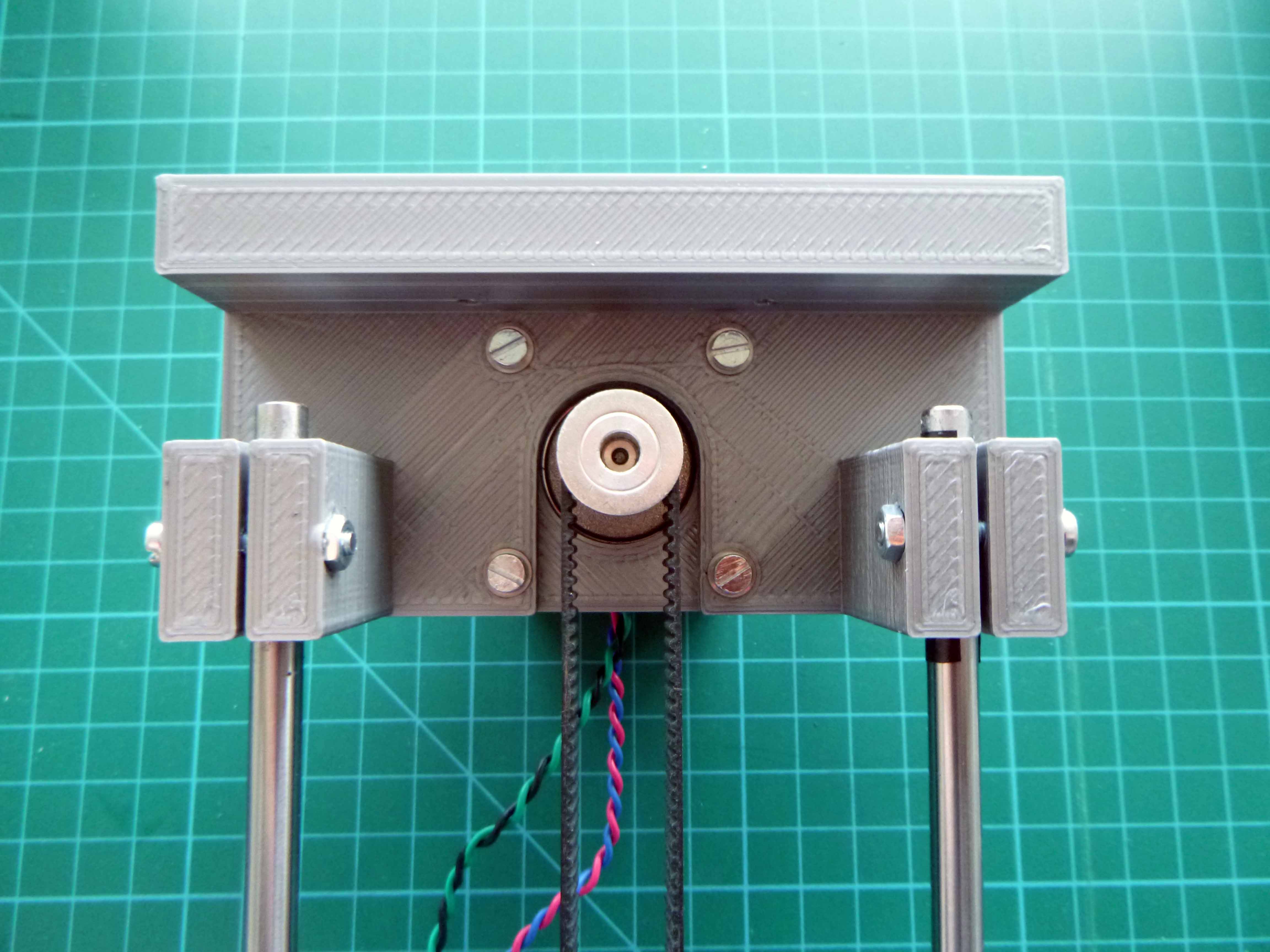
Here is the belt drive assembly:
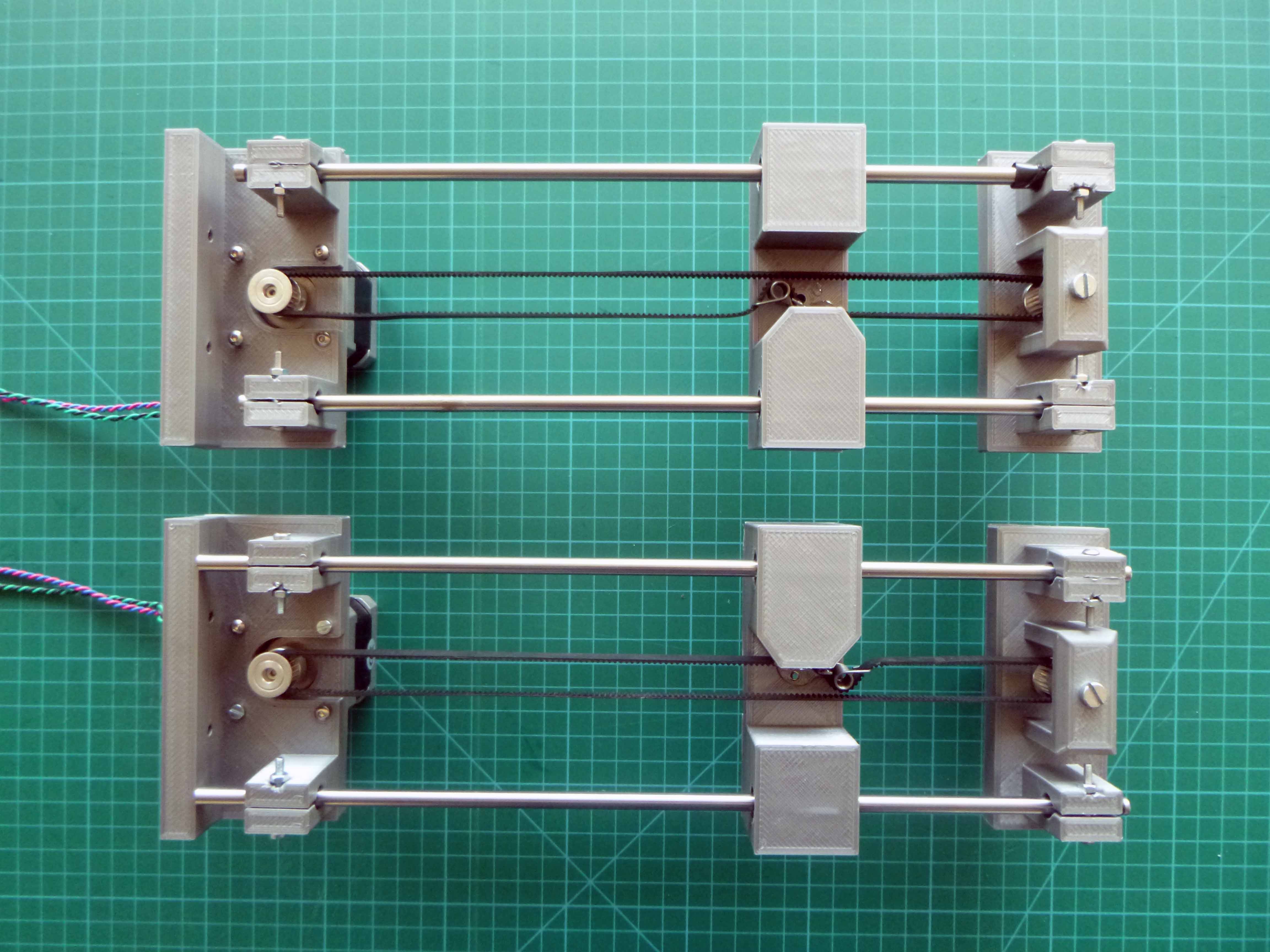
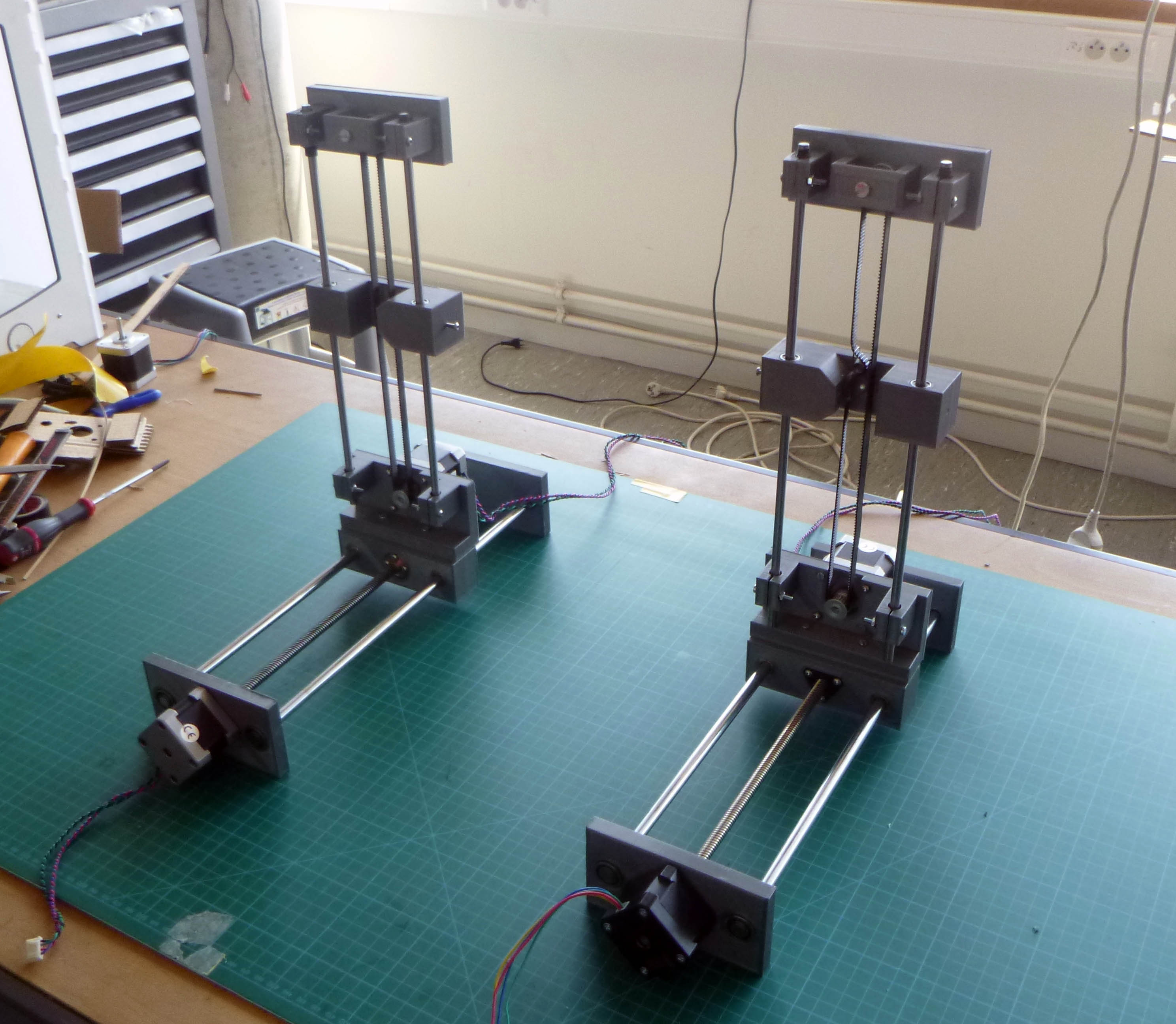
Here are the two axes completed:
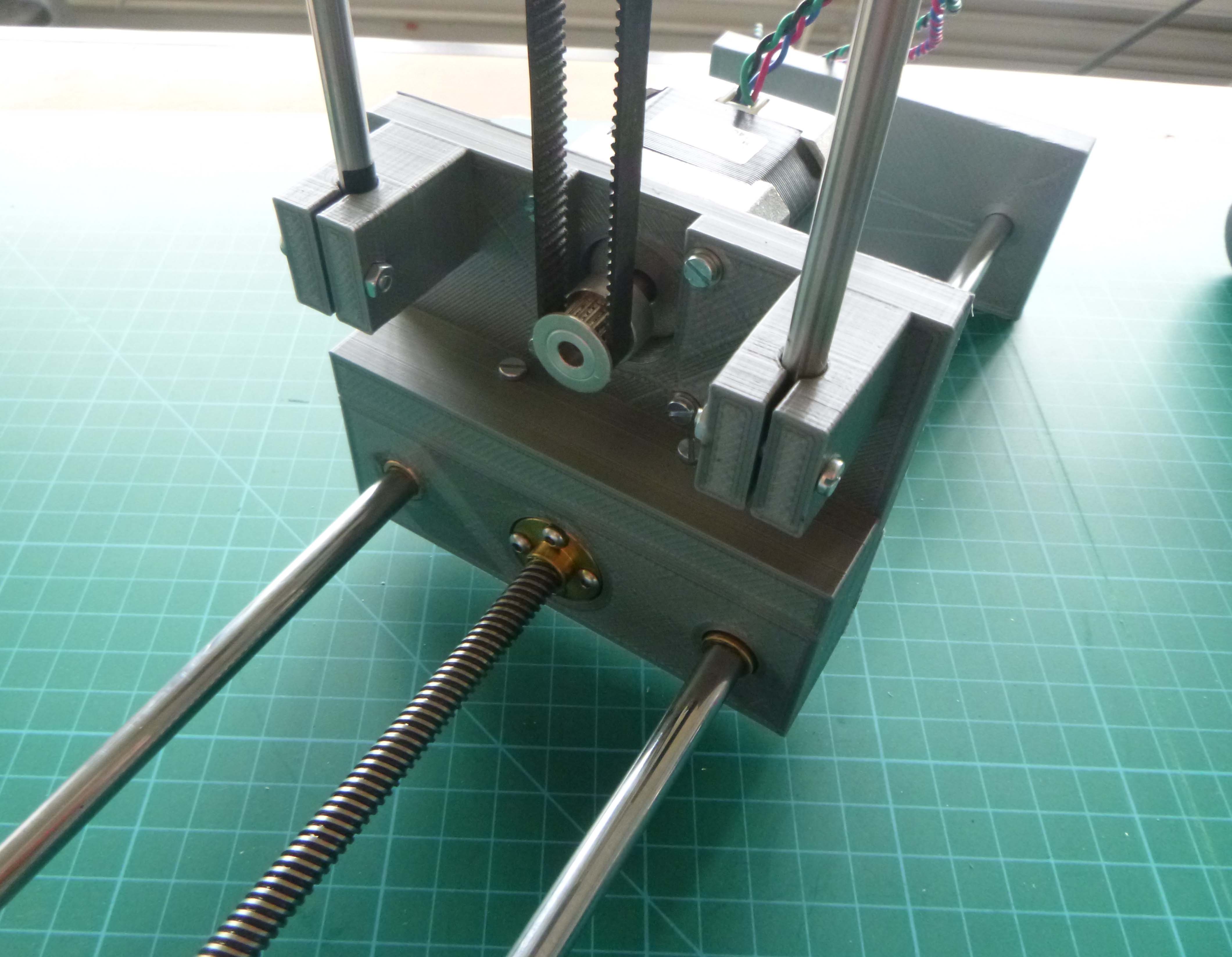
Here is the first of the two linear actuator drives:
Slight differences between the two based on different hardware but essentially the same:

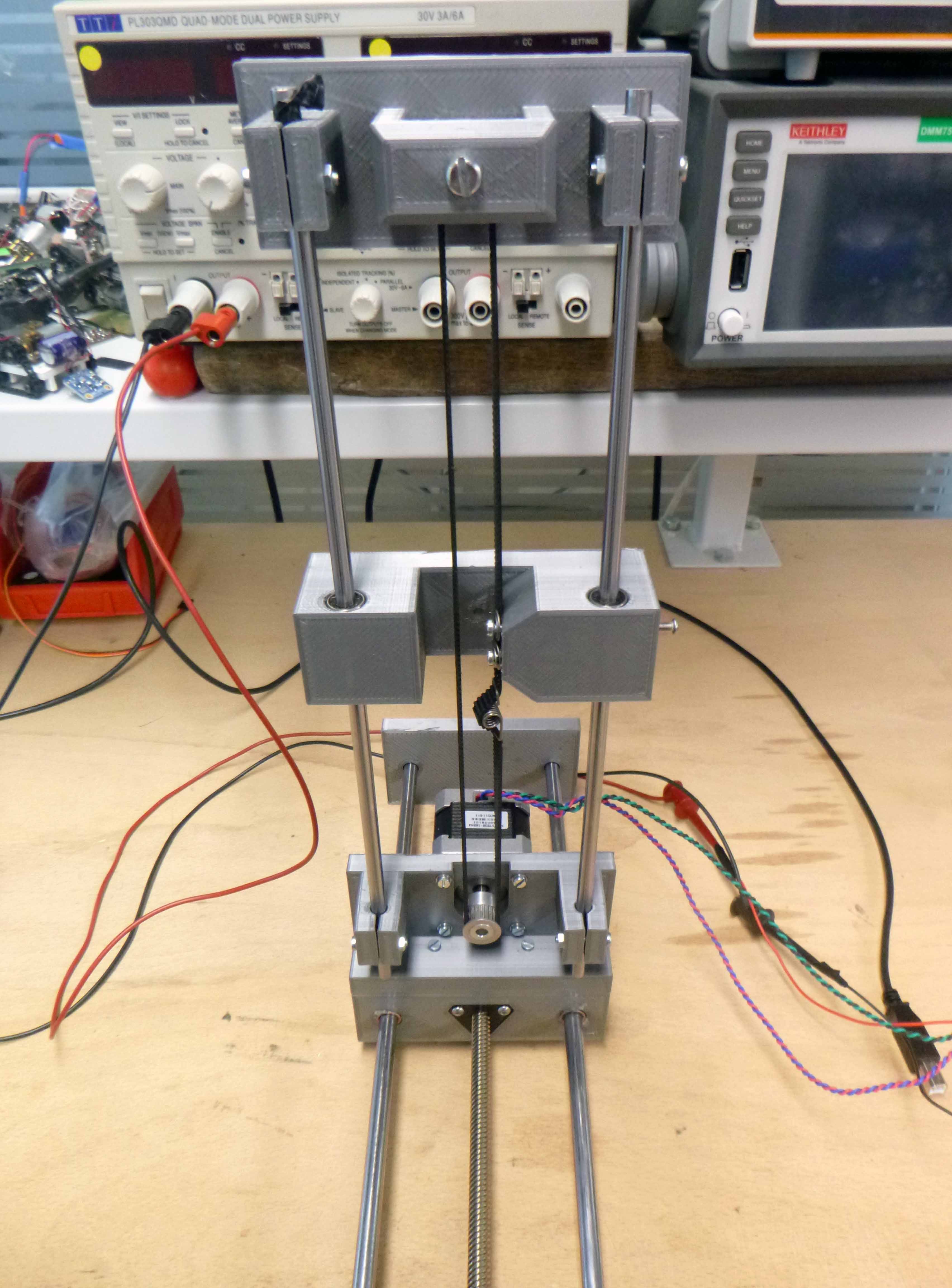
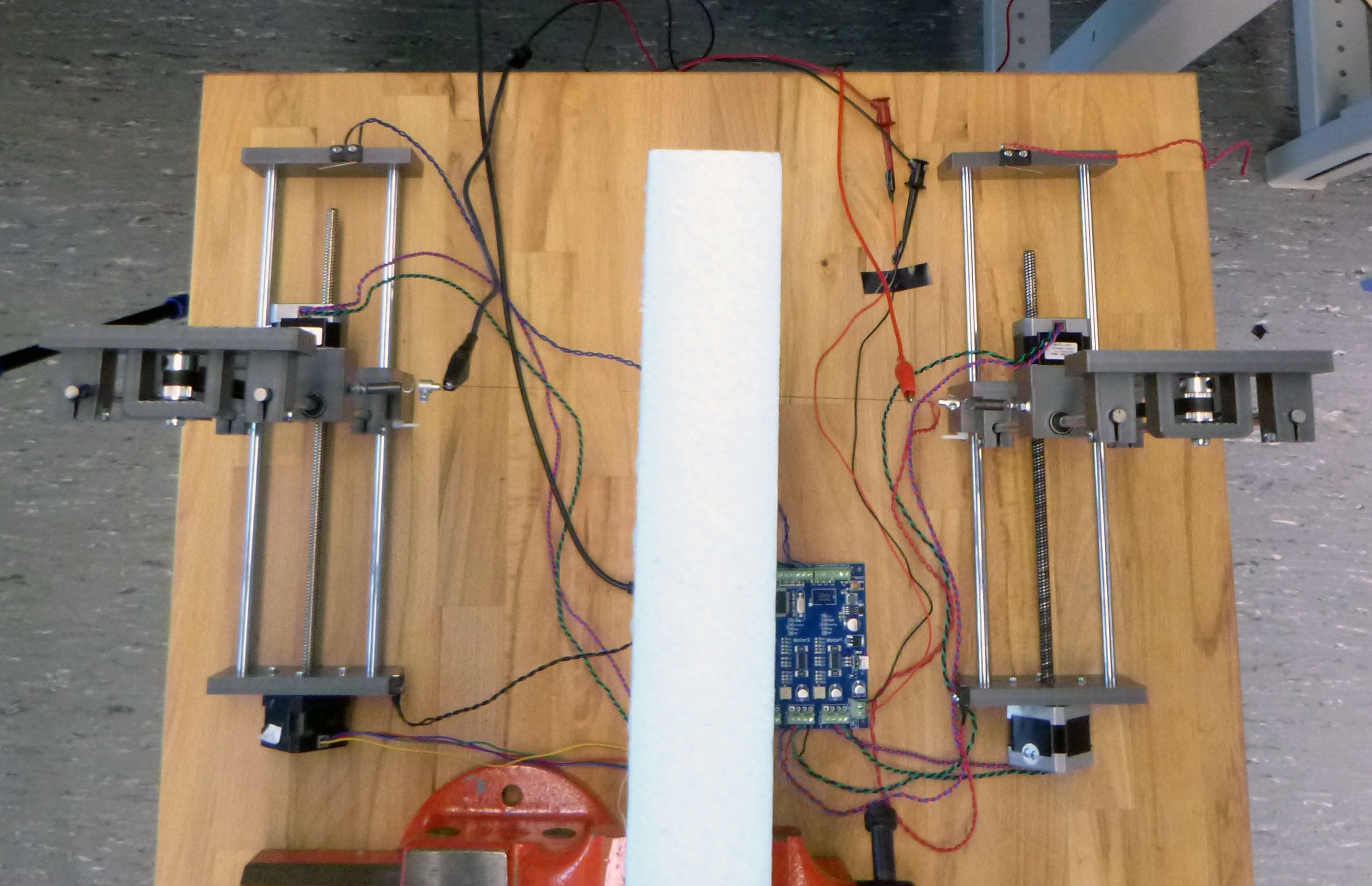
Here is the full assembly minus electronics:
 The electrical connections to the TinyG:
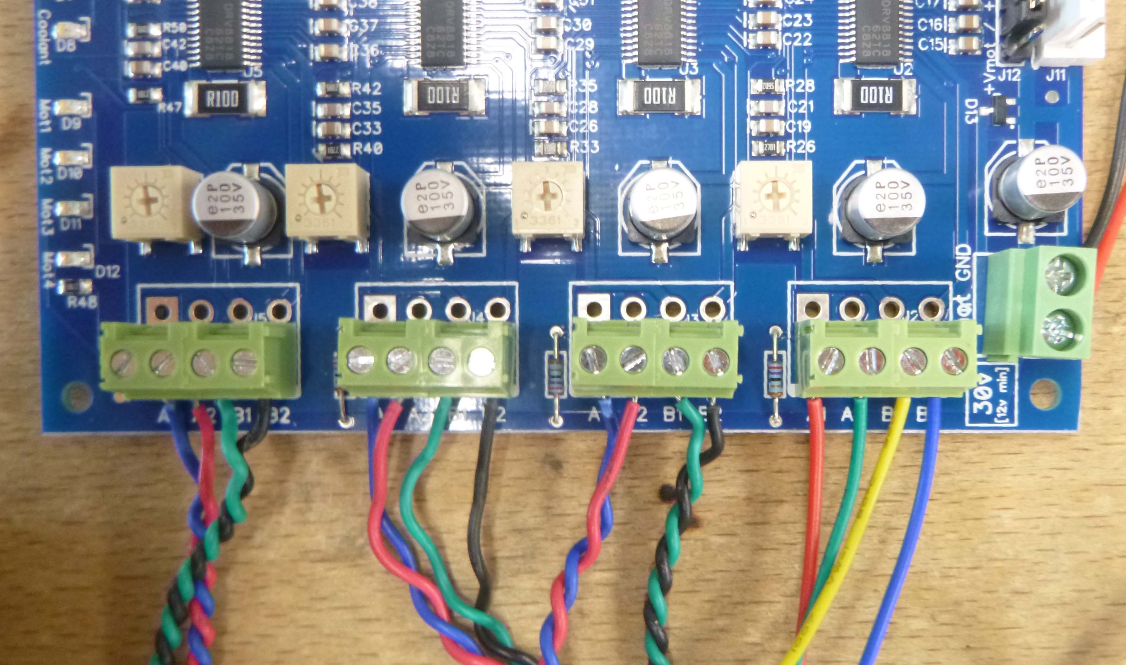
All plugged in and ready to go:

Using the webpage CNC controller Chilippeper :
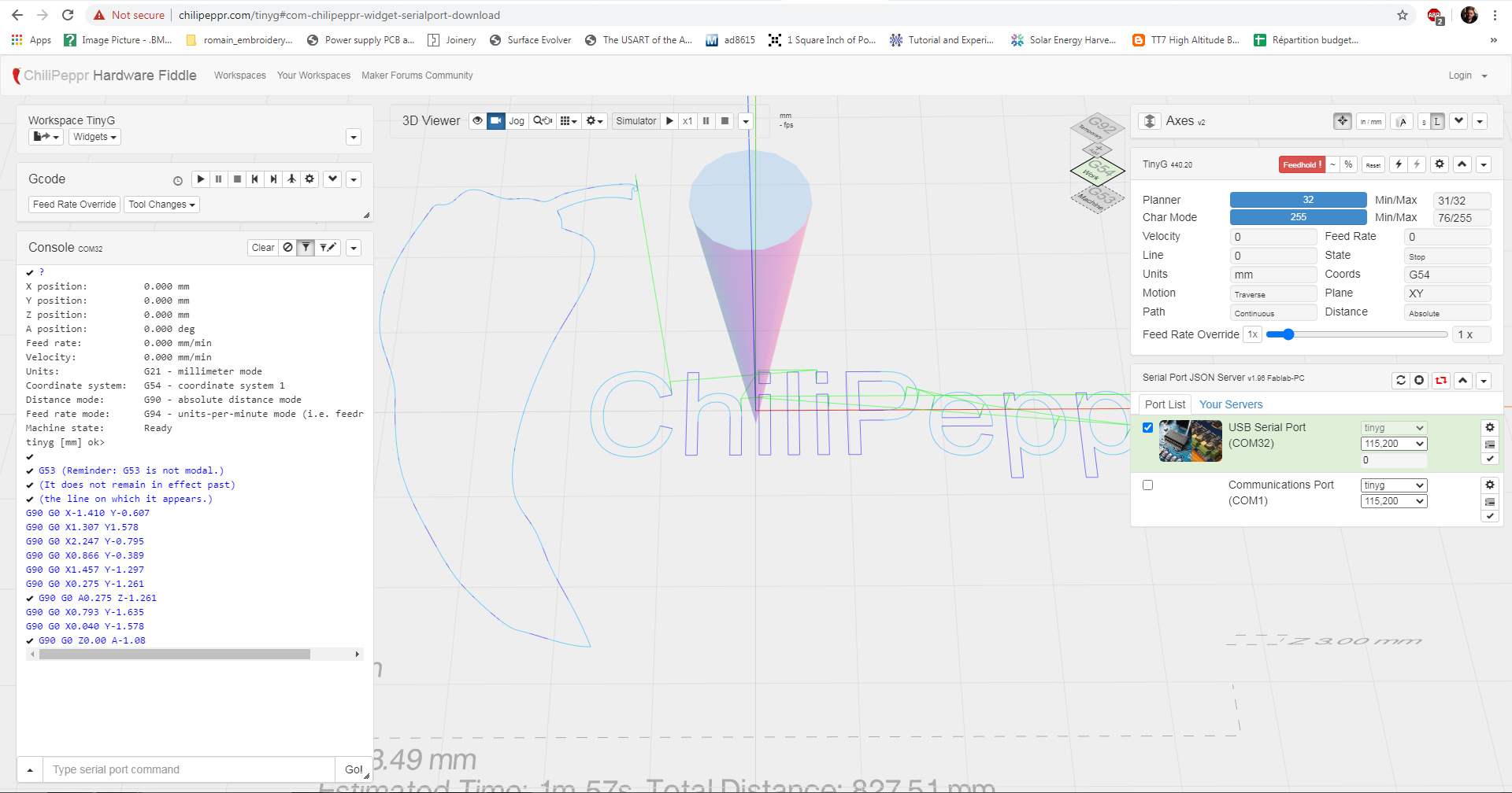
Running local JSON script to allow the website to access the COM ports, if I understand correctly:

Chilipeppr Configuration (https://github.com/synthetos/TinyG/wiki/TinyG-Configuration-for-Firmware-Version-0.97):
To change the Motor – Axis assignment in Chilipeppr:
$1ma=0 Maps motor 1 to the X axis
$2ma=1 Maps motor 2 to the Y axis
$3ma=0 Maps motor 3 to the X axis
$4ma=1 Maps motor 4 to the Y axis
To swap polarity of a motor:
$1PO
- 0 = Normal motor polarity
- 1 = Invert motor polarity
To set X axis minimum and maximum end stop limit switches (the switches connect GND to XMIN or XMAX on the Tiny G).
$XSN 3 and $XSX 3
To change the distance for every movement of 1mm:
$1tr VALUE
To change max feedrate in X:
$xfr
*************
Here is the video of the machine making its first moves:
**************
Here is a version two fixing some errors in the 3D modeling:
Linear actuator redesign (forgot to subtract the motor and threaded rod previously):
Here’s the finished belt-drive assembly:

I reprinted this part with 40% density instead of 20% (which broke last time when I tightened), corrected the diameter of the rods (which destroyed the rigity of the actuator), reoriented the embedded nut, and used shorter bolts:
Also 40% instead of 20%:
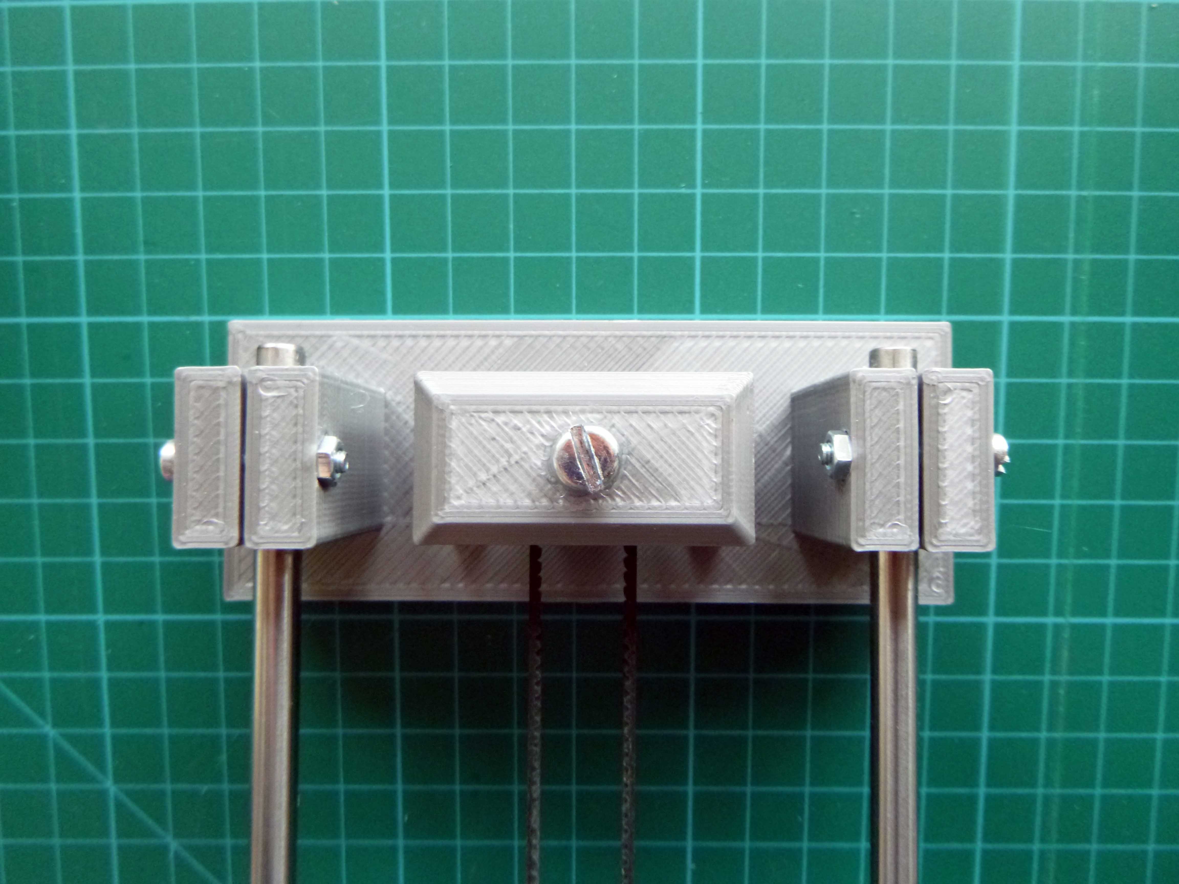
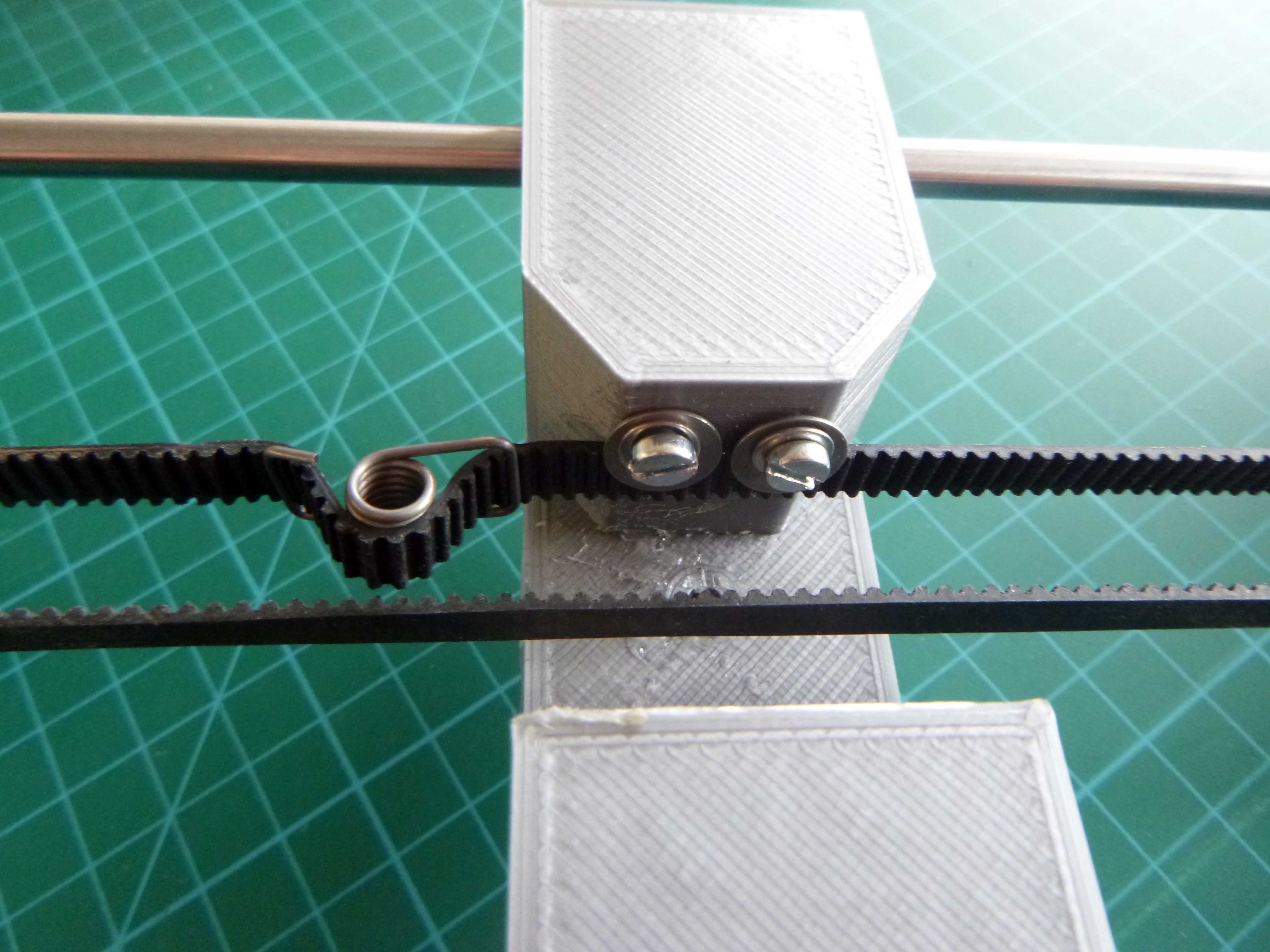
This was a bit tricky but using two bolts with washers I replaced the hot glue to fix the belt in place.
I corrected the orientation of the holes and the two actuators line up perfectly:
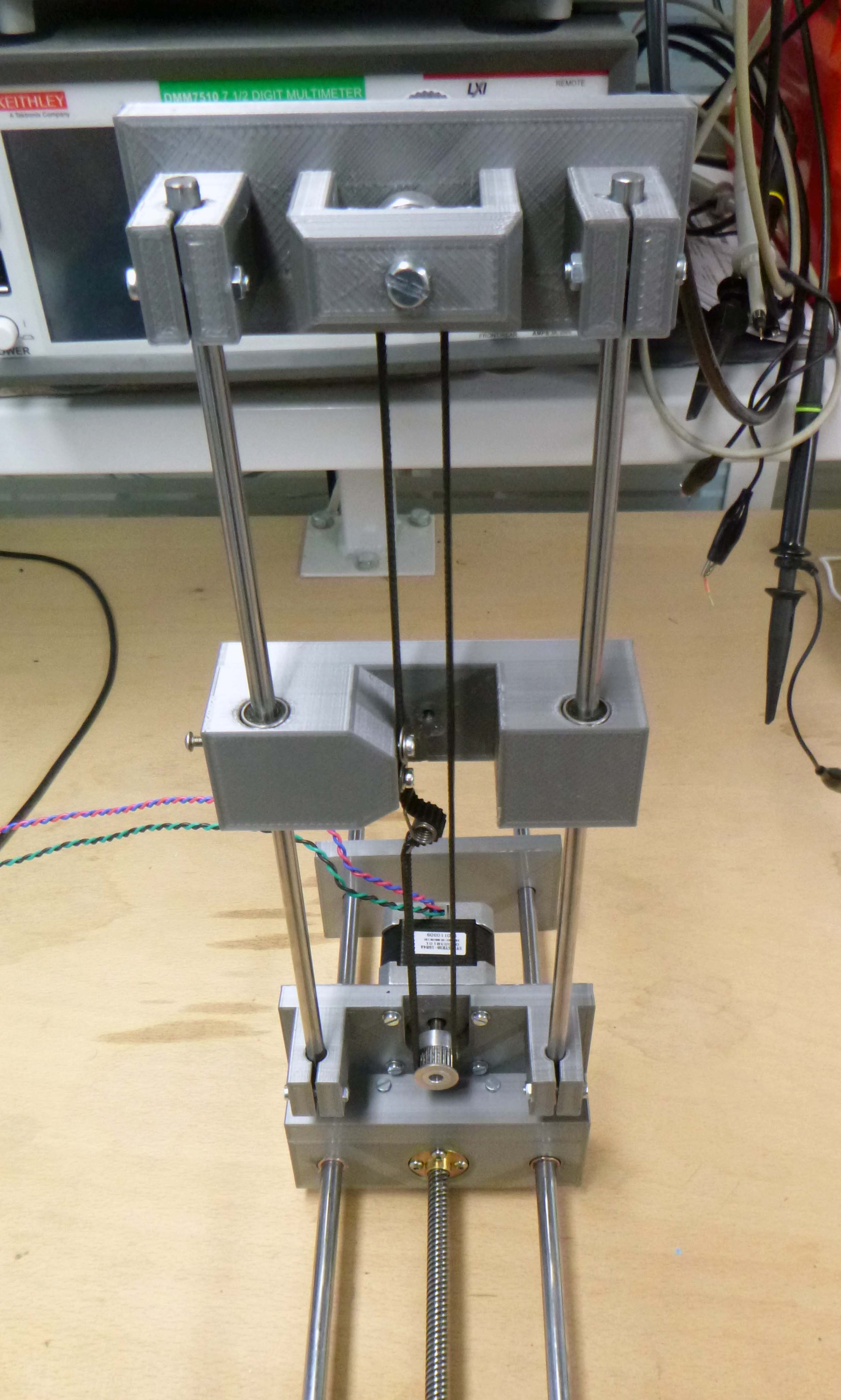
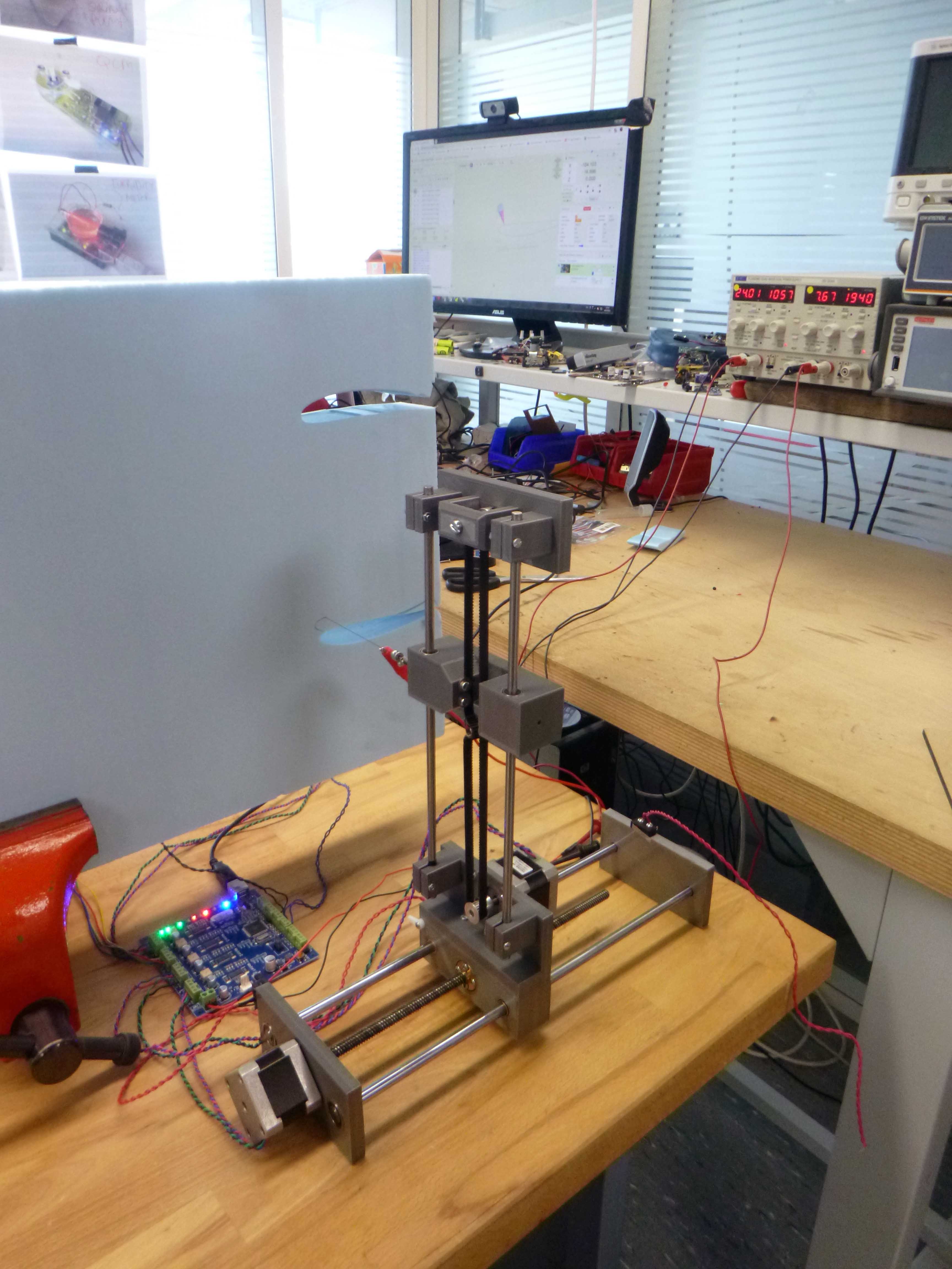
Here’s the final assembly version 2:
*************
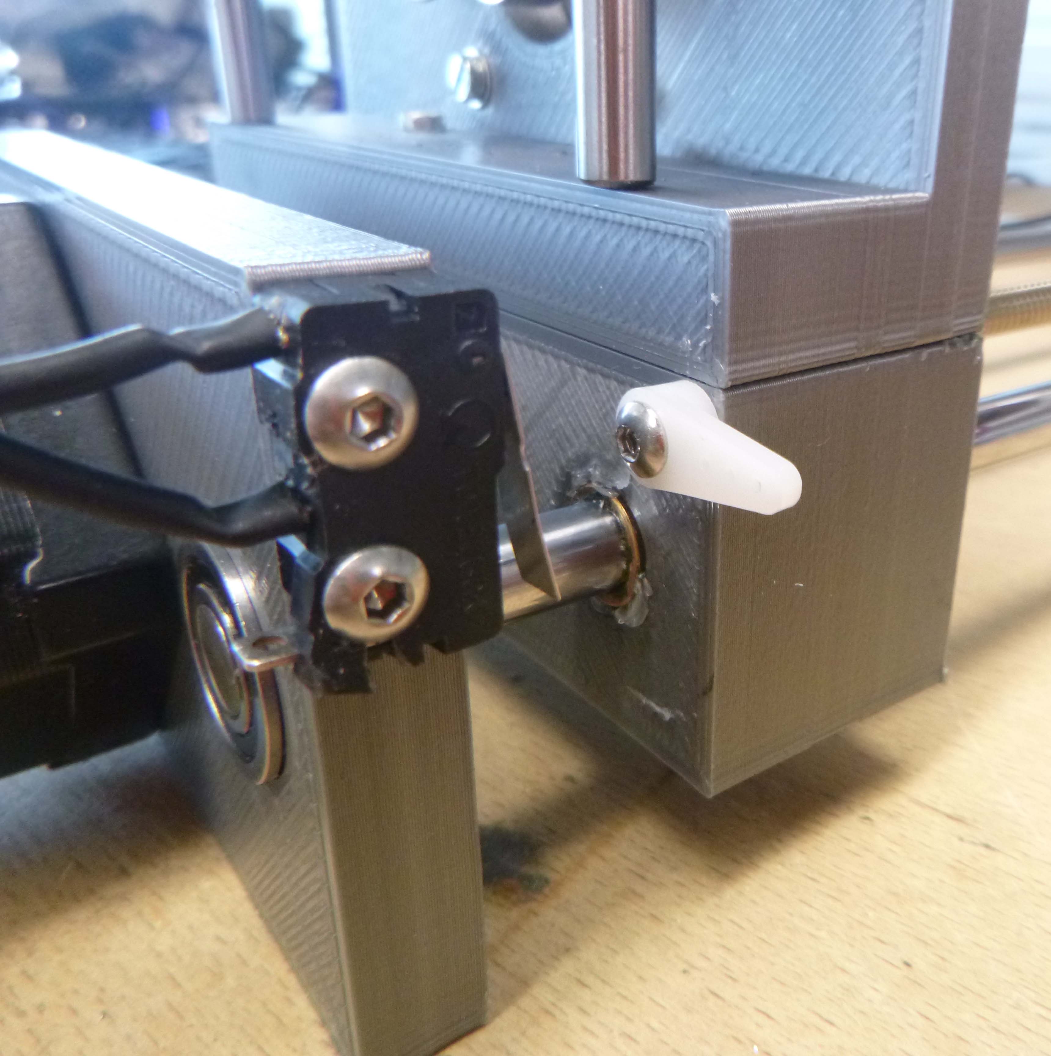
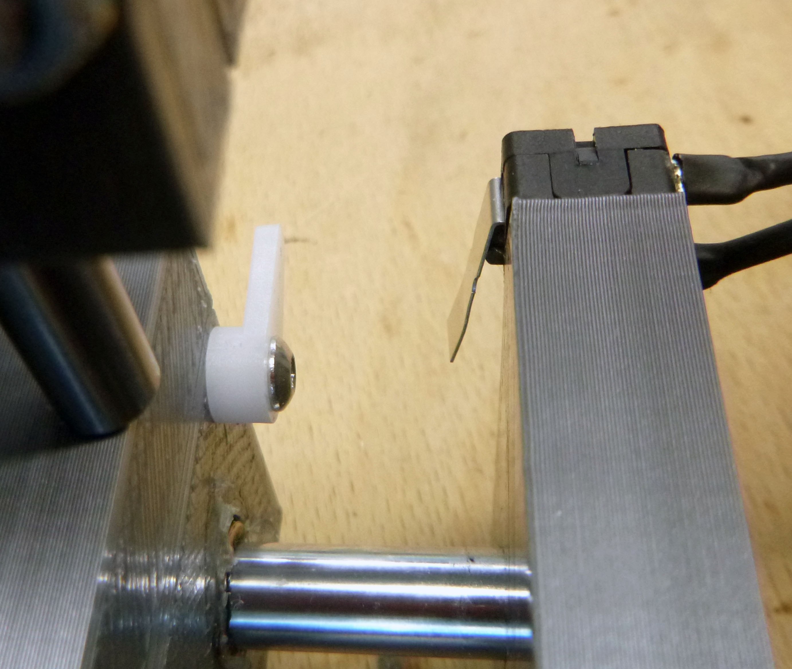
I’ve added some limit switches and have a preliminary setup for the hot wire cutting fixtures:

**************
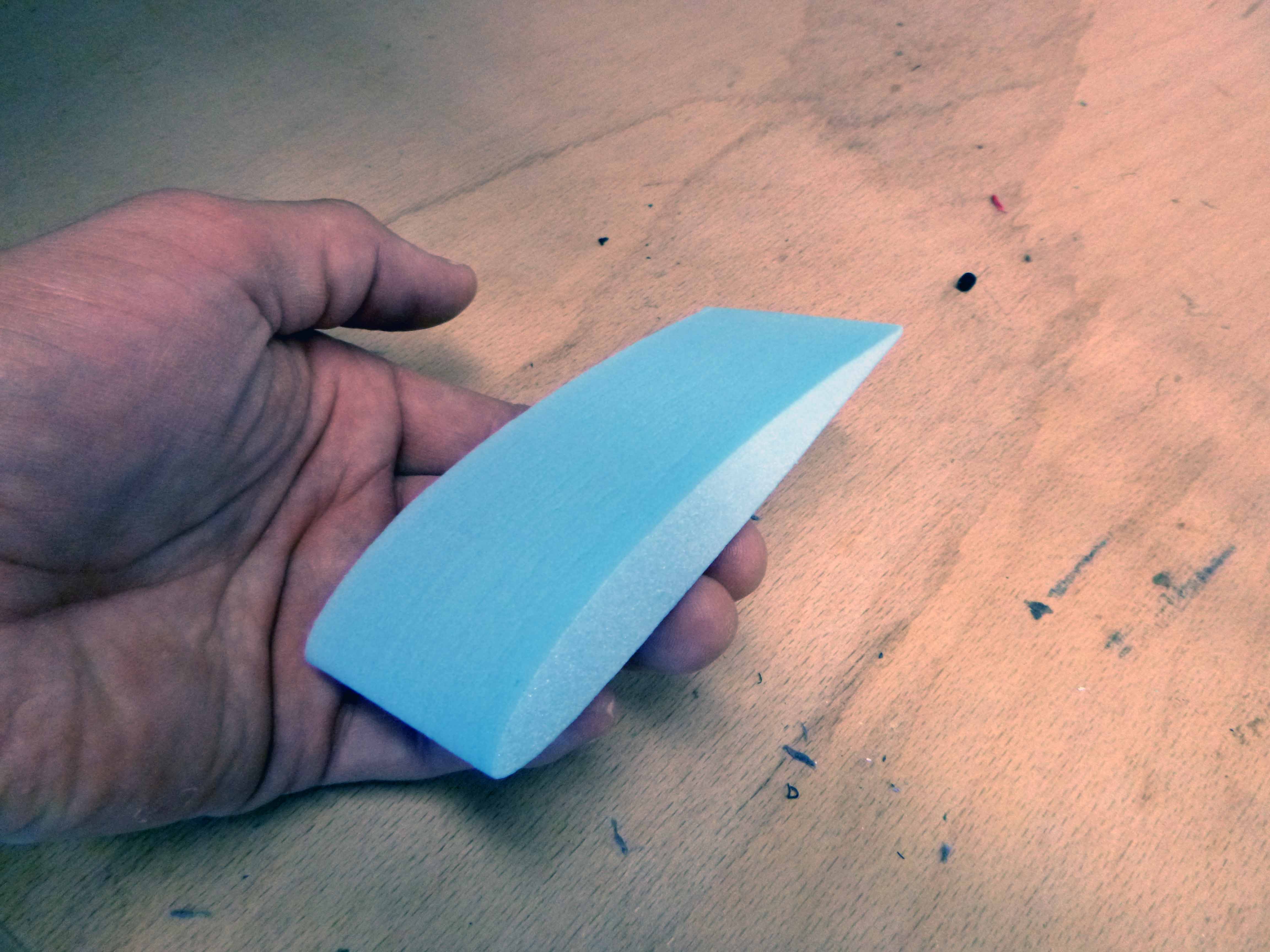
Here is the first test cut:
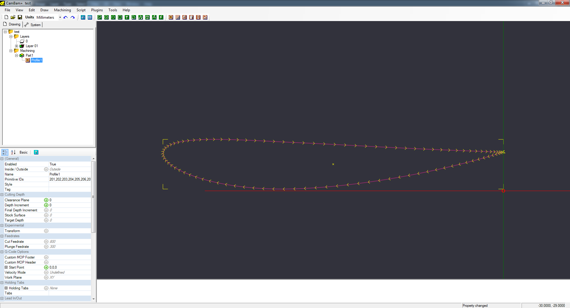
Here’s what it looked like on the software side:
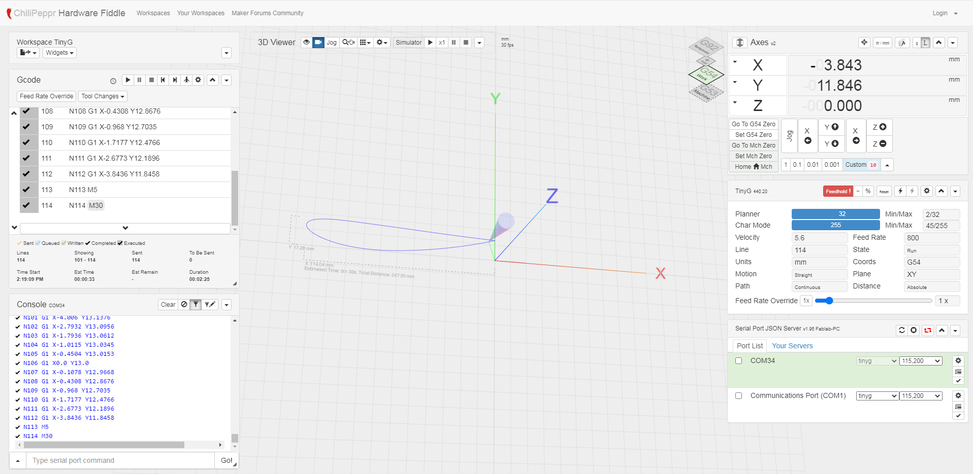
I used CAMBAM to take in a DXF and output the Gcode.
I had to additionally make everything related to the Z axis zero, and set the start point.