UPDATES :
- I can do a simple recording that doesn’t jump all over the place.
- I can record and playback 8 bits over time and write that as a byte to the SRAM now.
- I can record images in different banks of memory.
- I can record two bit recordings with two colors.
- I can record and playback in different resolutions
- XOR’ing a recording with the live feed is cool !
- I accidentally managed to get IceCube to infer a BRAM to hold my giant array and it worked
- I can now overlay a ROM image over SRAM recordings
- I can record in BRAM and use all 64K of it !
- I haven’t successfully managed to record 8 images in parallel into the SRAM however.
- I haven’t managed to record an “animation” yet.
- Still no dice with the OV7670 camera.
- I’ve got the HX4K FPGA programmed to blink and LED but am struggling with the screen atm.
*****
I have an opportunity to present this project for the Sketching in Hardware : RESEARCH AND DESTROY! conference in October.
the design and use of physical computing toolkits. tools for creating digital products, environments, and experiences: how to make them, why to make them (and why not), how to use them, how to teach with them, and how to understand their impact.
Serge has the following advice for my project :
It’s about art history, retracing the obsessions different artists had (especially minimalist artists who were trying to reduce the artwork to it’s fundamental parts : paint, canvas, color ) but having the machine rediscover these.
****
Different ways to use a fixed amount of memory (wikipedia) :
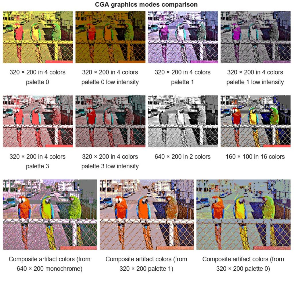
Low-fi images using shaded character boxes :
***
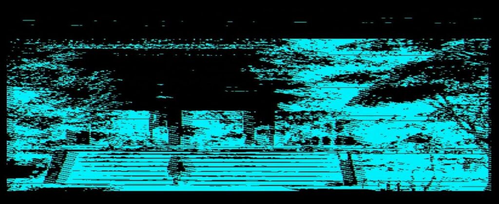
BRAM + SRAM recording :


Recording one bit at a time and only writing bytes to the SRAM makes this cool hash patterns :
Recording and then XOR’ing with the live feed :
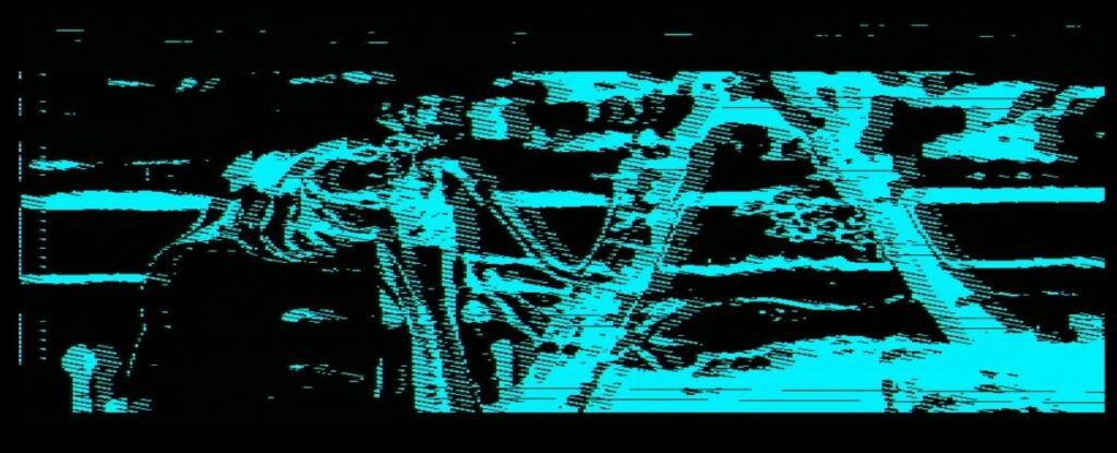
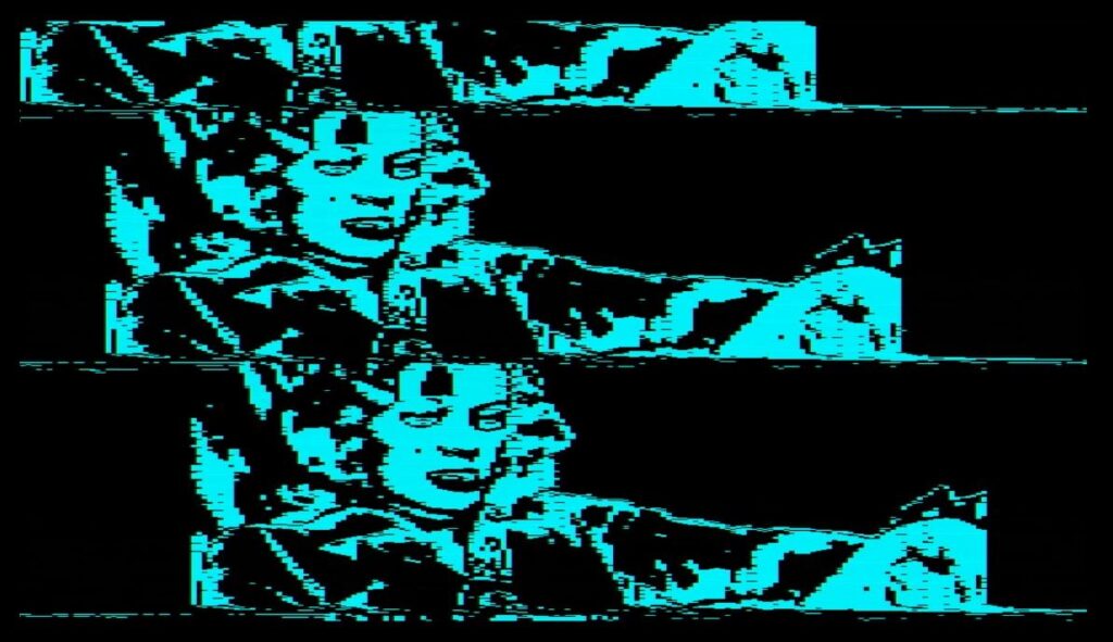
This glitch that kind of makes cool graphic novel effects from recordings :

Multi-color recordings :

TO DO :
buy camera for rpi zero- try more verilog experiments :
record and then xor recording with live feed- superimpose text over recording or live feed
- edit a saved image with a cursor
- fix freezing issue
- make recording multiple images more efficient (possibly by using DEN and loading recordings into a register like the ROM images?)
META STUFF from friend and artist Annie :
- Don’t have fear about how your project will be received !
- You are following the laws from a bunch of different countries (Industrial Design, Fine Art, Engineering, Hobby tech world). They are presenting too many constraints. Chose to be part of one permissible country, like the Fine Art one, and take the project to its conclusion. In this country you can follow your intuition and desires for the project in the current moment, and avoid getting paralysed speculating about the future. Once you’ve got something you can always chose to go back and redo it super well so that it can become a product.
******
Trying to map out how to make the BRAM line buffer to work with SRAM to do 8 parallel recordings :
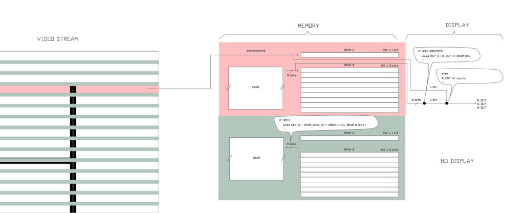
I tried to create an SRAM module like the BRAM one but IceCube2 won’t allow a module to have connections with physical pins it appears.
***
OK, I have got rpi recording working reliably 🙂 I also played with different clock divisions, recorded with rpi clock and PB with the FPGA clock, tried recording animations (failed), and tried recording two images in different parts of SRAM.
My process so far : I keep the programmer plugged in but disconnect from the USB after uploading. I reset the FPGA after programming every time (unglug and replug in USB), and delete and recreate + deactivate and reactivate the recording device in OBS studio after unplugging and replugging in the USB each time. I’m using male-female jumpers to go from the rpi to the FPGA. The rpi is powered seperately. I’m using a VGA capture and OBS studio.
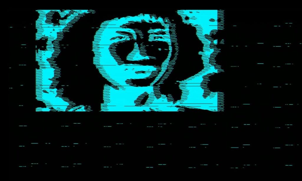
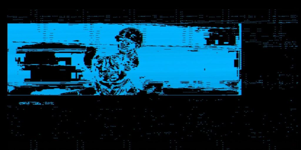
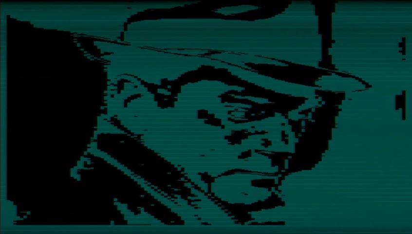
Left is the original (Green 5 in DPI mode) and right is the playback (inverted) from SRAM :

Here is the code :
module verilog(
input wire rec,
input wire clk,
input wire rpi_h_sync,
input wire rpi_v_sync,
input wire rpi_color,
output reg [17:0] addr,
inout wire [7:0] io,
output wire cs,
output reg we,
output wire oe,
output wire h_sync,
output wire v_sync,
output reg [3:0] r_out,
output reg [3:0] g_out,
output reg [3:0] b_out
);
assign cs = 0;
assign oe = 0;
assign h_sync = rpi_h_sync;
assign v_sync = rpi_v_sync;
wire [7:0] data_in;
wire [7:0] data_out;
assign data_in[7:0] = (rpi_color == 1'b1) ? 8'b11111111 : 8'b00000000; // color from rpi
reg [7:0] a, b;
assign io = (rec==0) ? a : 8'bzzzzzzzz;
assign data_out = b;
reg [3:0] counter = 0; //our clock divider
//SRAM address counter
always @(posedge clk) begin
counter <= counter + 1;
if (counter[2]) begin
if(rpi_v_sync) begin // reset the SRAM each time we draw a new frame
addr <= 0;
end
else begin
addr <= addr+1;
end
end
end
always @(posedge counter[2]) begin
b <= io;
a <= data_in;
if (rec==0) begin
we <= addr[0]; //not sure why it isn't the inverse of addr[0] but that doesn't make the inverse on 'scope
end
else begin
we <= 1;
end
end
always @(posedge counter[2]) begin
if ((rec==0) && (a==8'b11111111))
begin
r_out[0] <= 1'b0;
r_out[1] <= 1'b0;
r_out[2] <= 1'b0;
b_out[0] <= 1'b0;
b_out[1] <= 1'b0;
b_out[2] <= 1'b0;
g_out[0] <= 1'b0;
g_out[1] <= 1'b0;
g_out[2] <= 1'b0;
end
else if ((rec==0) && (a==8'b00000000))
begin
r_out[0] <= 1'b1;
r_out[1] <= 1'b1;
r_out[2] <= 1'b0;
b_out[0] <= 1'b1;
b_out[1] <= 1'b1;
b_out[2] <= 1'b0;
g_out[0] <= 1'b1;
g_out[1] <= 1'b1;
g_out[2] <= 1'b0;
end
else if ((rec==1) && (b==8'b11111111)) //data_out not b ??
begin
r_out[0] <= 1'b1;
r_out[1] <= 1'b0;
r_out[2] <= 1'b1;
b_out[0] <= 1'b1;
b_out[1] <= 1'b0;
b_out[2] <= 1'b1;
g_out[0] <= 1'b1;
g_out[1] <= 1'b0;
g_out[2] <= 1'b1;
end
else
begin
r_out[0] <= 1'b1;
r_out[1] <= 1'b0;
r_out[2] <= 1'b0;
b_out[0] <= 1'b1;
b_out[1] <= 1'b0;
b_out[2] <= 1'b0;
g_out[0] <= 1'b1;
g_out[1] <= 1'b0;
g_out[2] <= 1'b0;
end
end
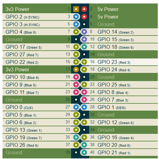
endmoduleAnd the constraints :
set_io clk 58

set_io rpi_h_sync 62
set_io rpi_v_sync 61
set_io rpi_color 52

set_io h_sync 76
set_io v_sync 97

set_io rec 47

set_io r_out[0] 91 //for vga
set_io r_out[1] 95 //for vga
set_io r_out[2] 96 //for vga

set_io b_out[0] 87 //for vga
set_io b_out[1] 88 //for vga
set_io b_out[2] 90 //for vga

set_io g_out[0] 75 //for vga
set_io g_out[1] 74 //for vga
set_io g_out[2] 73 //for vga

set_io io[0] 7
set_io io[1] 8
set_io io[2] 9
set_io io[3] 10
set_io io[4] 11
set_io io[5] 12
set_io io[6] 19
set_io io[7] 22

set_io addr[0] 4
set_io addr[1] 3
set_io addr[2] 2
set_io addr[3] 1
set_io addr[4] 144
set_io addr[5] 143
set_io addr[6] 142
set_io addr[7] 141
set_io addr[8] 120
set_io addr[9] 121
set_io addr[10] 24
set_io addr[11] 122
set_io addr[12] 135
set_io addr[13] 119
set_io addr[14] 134
set_io addr[15] 116
set_io addr[16] 129
set_io addr[17] 128


set_io cs 25
set_io oe 23
set_io we 118
And here are some of the documents that were helpful :

***
Successful BRAM implementation :
module ram (din, addr, write_en, clk, dout);// 512x8

parameter addr_width = 15;
parameter data_width = 2;
input [addr_width-1:0] addr;
input [data_width-1:0] din;
input write_en, clk;
output [data_width-1:0] dout;
reg [data_width-1:0] dout; // Register for output.
reg [data_width-1:0] mem [(1<<addr_width)-1:0];

always @(posedge clk)
begin
if (write_en==0)
mem[(addr)] <= din;
else
dout = mem[addr]; // Output register controlled by clock.
end
endmodule
And the top module :
module top (

input wire rec,
input wire FPGA_clk,
input wire rpi_h_sync,
input wire rpi_v_sync,
input wire rpi_color,

output wire h_sync,
output wire v_sync,
output wire [1:0] r_out,
output wire [1:0] g_out,
output wire [1:0] b_out
);

assign h_sync = rpi_h_sync;
assign v_sync = rpi_v_sync;

parameter addr_width = 15;
parameter data_width = 2;

reg [addr_width-1:0] address;
wire [data_width-1:0] data_in;
wire [data_width-1:0] data_out; // Register for output.

assign data_in = {8{rpi_color}};

assign r_out = data_out[1:0];
assign g_out = data_out[1:0];
assign b_out = data_out[1:0];

reg [3:0]counter;

always @(posedge FPGA_clk) begin

counter <= counter + 1;

end

always @(posedge counter[1]) begin

if(rpi_v_sync) begin // reset the SRAM each time we draw a new frame
address <= 0;
end

else begin
address <= address+1;
end
end

ram ram0(
.din(data_in),
.addr(address),
.write_en(rec),
.clk(counter[1]),
.dout(data_out)
);

endmodule
Now to implement the line buffer to store 8 channels of 1 bit recordings !
********
Using the only working Arduino library I could find I can get a kind of VGA out of the OV7670 but it remains extremely slow.
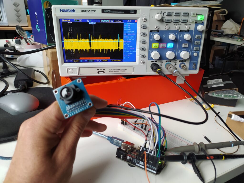
***EDIT I looked into this (https://github.com/AngeloJacobo/FPGA_OV7670_Camera_Interface) and to get a live feed working with an FPGA is a challenge involving multiple clock domains, BRAM, etc. I could work with the images I can capture slowly ?
****
I am preparing to test the TFT screen using these two datasheets :
https://cdn-shop.adafruit.com/product-files/2770/SPEC-CH280QV10-CT_Rev.D.pdf
https://cdn-shop.adafruit.com/datasheets/ILI9341.pdf
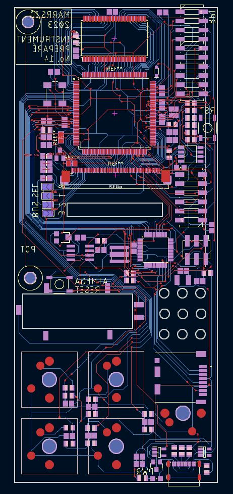
I’ve recovered the lost PCB file by using the gerbers sent to PCB way and KiCAD :
***EDIT : I’ve learned something while programming this board. It was floating in some kind of reset state. Always have a blinking light that shows that the board is out of reset. Also, check that IceCube hasn’t randomly rejected and reassigned the pins you have assigned in the pcf.
So far I am only getting grey lines :
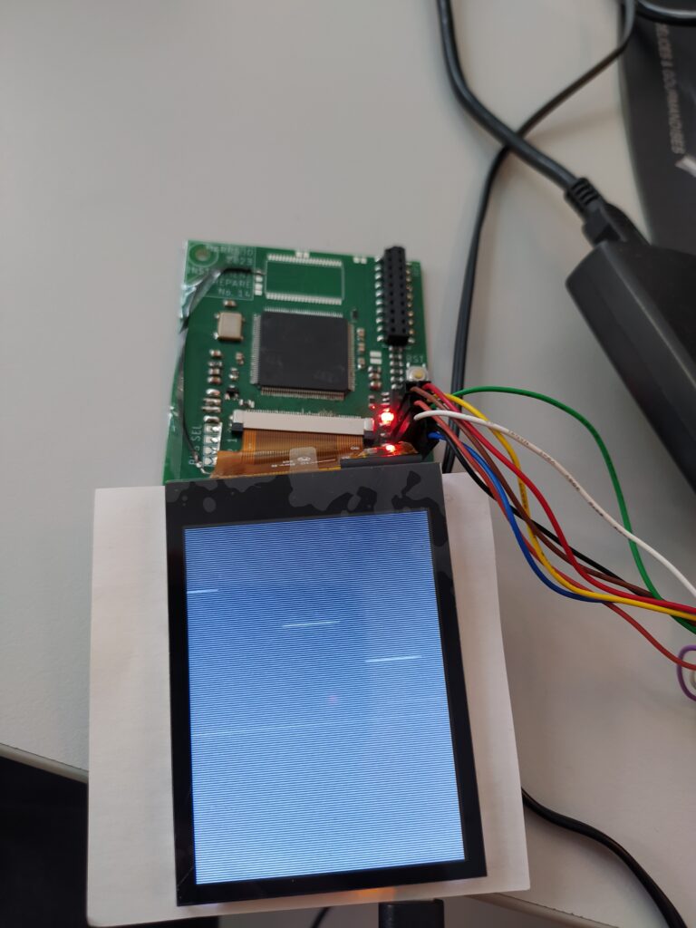
I’m using the MCU parallel interface for the moment :
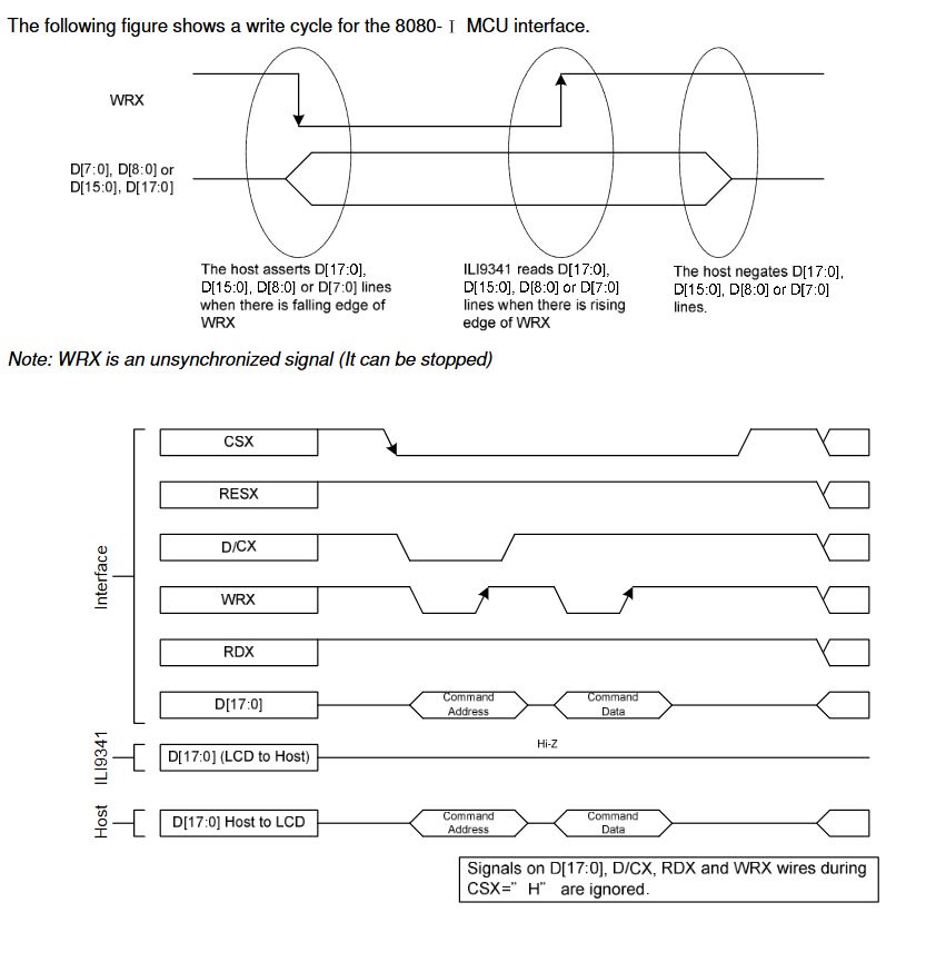
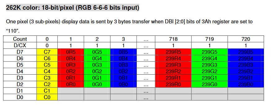
Here is how the colors are sent :
Here is my test file :
//8080 MCU 8-bit bus interface I
// solder all IM sel bits to GND

//D[7:0],WRX,RDX,CSX,DCX

`default_nettype none

module top(
input wire clk,
output reg [7:0] TFT_DB,
output reg [9:0] TFT_DB_GND,
output reg TFT_WRX,
output wire TFT_RDX,
output wire TFT_CSX,
output reg TFT_DCX,
output wire TFT_BACKLIGHT_MOSFET,
output wire TFT_RESX,
output wire LED
);


assign TFT_DB [17:8] = 10'b0000000000; // connect unused DB pins to GND
assign TFT_BACKLIGHT_MOSFET = 1'b1; // turn on
assign TFT_CSX = 1'b0; //chip sel low
assign TFT_RESX = 1'b1; //reset held high (but might need to reset it to get it working according to data sheet?)
assign TFT_RDX = 1'b1; // only writing no reading !

reg [7:0] counter ;
reg [18:0] loop_count ;

always @(posedge clk) begin
counter <= counter + 1;
end

reg [10:0] state;

localparam ADDR = 1'b0;
localparam DATA = 1'b1;

localparam LOW = 1'b0;
localparam HIGH = 1'b1;

localparam MEMORY_WRITE = 8'b00101100; //2Ch
localparam SLEEP_OUT = 8'b00010001; //11h
localparam SOFTWARE_RESET = 8'b00000001; //01h
localparam DISPLAY_ON = 8'b00101001; //29h


// WRITE COMMAND CODE
localparam a1 = 10;
localparam a2 = 12;
localparam a3 = 14;

// WRITE COMMAND CODE
localparam b1 = 20;
localparam b2 = 22;
localparam b3 = 24;

// WRITE COMMAND DATA
localparam c1 = 30;
localparam c2 = 32;
localparam c3 = 34;
localparam c4 = 36;
localparam c5 = 38;
localparam c6 = 40;
localparam c7 = 42;
localparam c8 = 44;


always @(posedge counter[1]) begin

state <= state + 1;

if (state == a1) begin
//t0
TFT_WRX <= HIGH;

end
if (state == a2) begin
//t1
TFT_WRX <= LOW;// transition from high to low
TFT_DCX <= ADDR; // signaling ADDRESS
TFT_DB [7:0] <= SLEEP_OUT; // 11h
end
if (state == a3) begin
//t2
TFT_WRX <= HIGH; // transition from low to high
end


if (state == b1) begin
//t0
TFT_WRX <= HIGH;

end
if (state == b2) begin
//t1
TFT_WRX <= LOW;// transition from high to low
TFT_DCX <= ADDR; // signaling ADDRESS
TFT_DB [7:0] <= DISPLAY_ON; //
end
if (state == b3) begin
//t2
TFT_WRX <= HIGH; // transition from low to high
end


if (state == c1) begin
//t0
TFT_WRX <= HIGH;

end
if (state == c2) begin
//t1
TFT_WRX <= LOW;// transition from high to low
TFT_DCX <= ADDR; // signaling ADDRESS
TFT_DB [7:0] <= MEMORY_WRITE; // 2C << MEMORY WRITE
end
if (state == c3) begin
//t2
TFT_WRX <= HIGH; // transition from low to high
end

// WRITE COMMAND DATA

if (state == c5) begin
//t0
TFT_DB [7:2] <= 6'b101010; //prepare data to write
TFT_WRX <= LOW; // transition from high to low
TFT_DCX <= DATA; // signaling DATA
end
if (state == c6) begin
//t1
TFT_WRX <= HIGH; // transition from low to high
end
if (state == c7) begin
//t2
if(loop_count < 76799) begin
state <= c4; // LOOP times 76 800 (320x240)
loop_count <= loop_count + 1;
end
end
end
endmodule