Just a reminder, try to make stuff that is pretty that people will enjoy, not just stuff that is meaningful to me. It makes life so much easier.
Also, I have chosen to learn teaching, not being an artist. I like that teaching renders a service, and has a social dimension. It uses more of my skill sets, is more useful for employment, and has less silliness.
***
Looking at the CVI documentation, (http://cmi.steverance.com/fairlight_docs/CVI_User_Manual.pdf) some great slides showing effects :
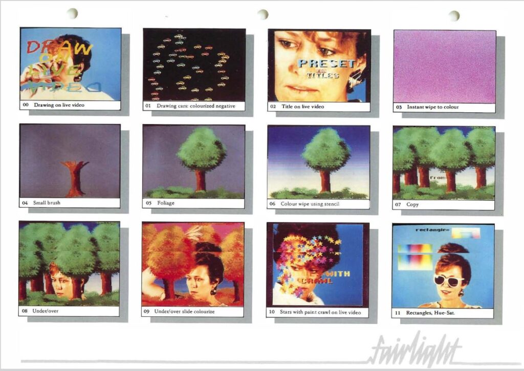

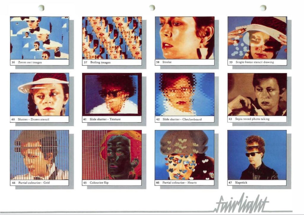
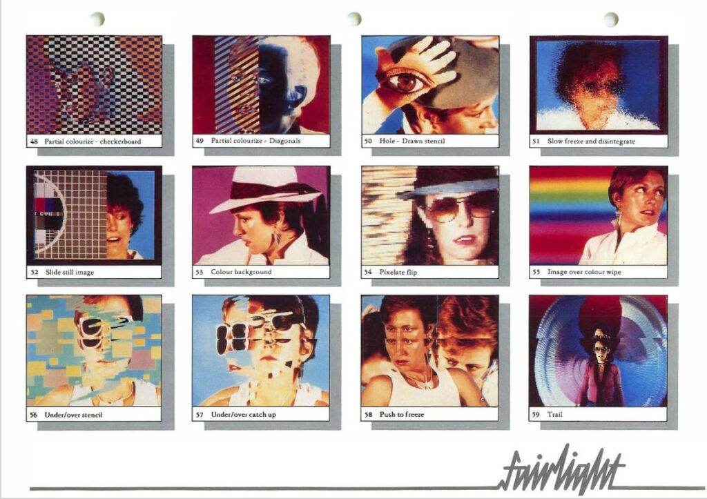


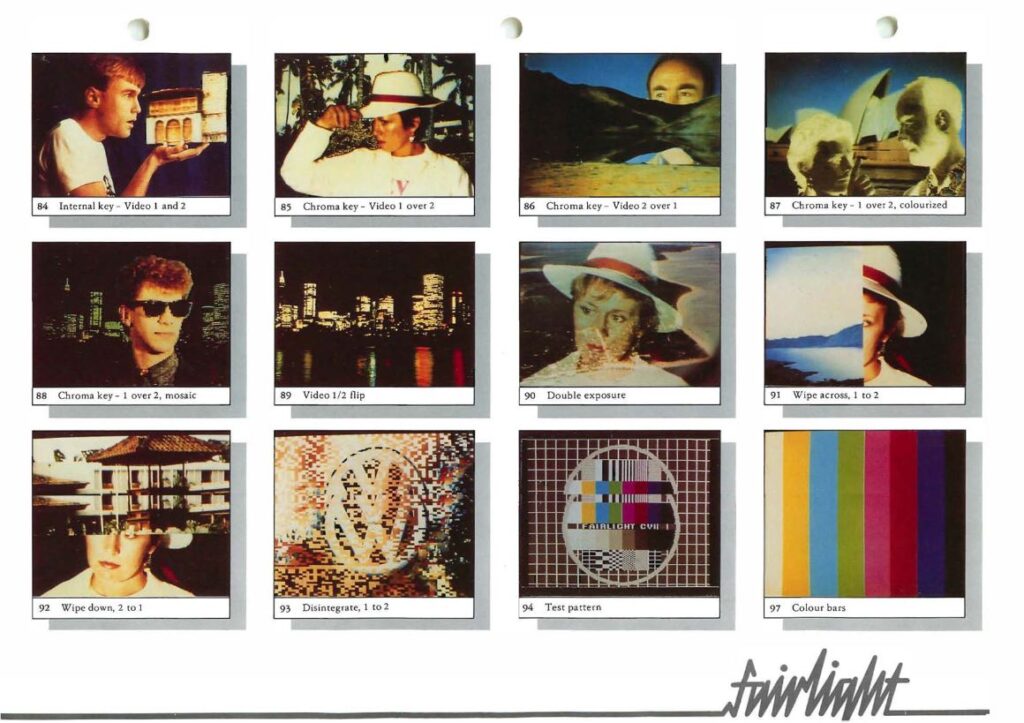
They all rely on having a screen buffer, where images taken from the live feed or sprites can be placed, and being able to mix (AND, OR, XOR, chroma keyed, analog mixed, etc.) that with live video. Predefined animations (shapes, random colors, gradients) can be added to these, and live video can also be filtered (pixelated, colorized, inverted, etc.).
One thing here I haven’t tested at all is recording an image and then recording another and creating a trail, for instance, what they appear to be calling Catch-Up, Doppelganger, and Trailing.
Now that I can store an image in memory, I could go back through it and modify it. I could invert, mirror, highlight edges, or do what they call a Checkerboard Slide shatter etc.
*******
Recording multiple images to overlay is difficult without a memory that has a write mask (as in case of BRAM) or byte enable pins on an SRAM, or having several seperate SRAMs. With the FPGA I’ve tried to quickly read the SRAM, store its contents, XOR with what I want to write, and then write that back, but haven’t had any success.
BRAMs with mask only apply to the 256×16 configuration. I can have 16 of these, but it means a only 4,096 pixels for the whole screen. Or a 64×64 pixel image like this :

Dual port SRAMs are small and very expensive, not sure there are useful for the project.
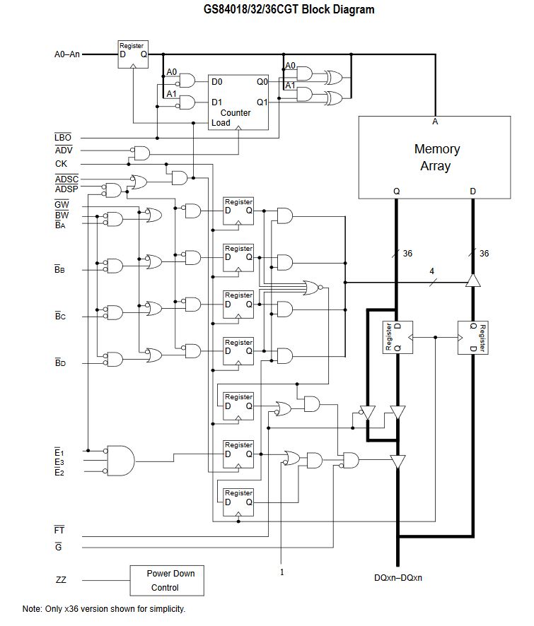
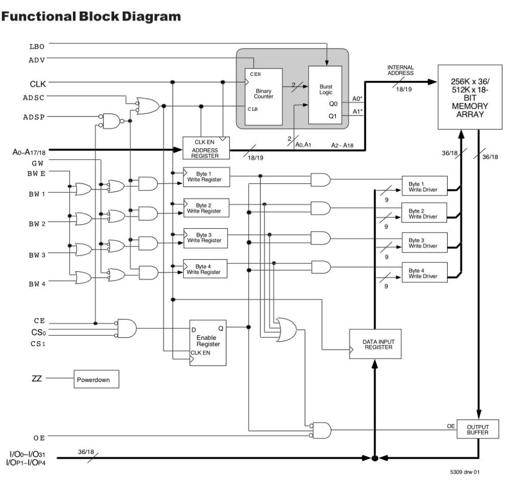
I could store four parallel images in the same memory space with these SRAMs which have four byte enable signals. Beware the High Byte and Low Byte enable pins from smaller SRAMs, it just toggles between two banks of I/O and doesn’t appear to do anything else.
GSI : https://www.mouser.fr/datasheet/2/771/840183236CGT-976441.pdf
Alliance : https://www.mouser.fr/datasheet/2/12/AS8C803625_801825-1288399.pdf
Rensas : https://www.mouser.fr/datasheet/2/698/REN_71V25761_DST_20200727-1995952.pdf
******
I am now imagining a new board which would have the following elements :
- INPUT
- Two video inputs with ESP32 and SD card : https://www.instructables.com/Play-Video-With-ESP32/
- delay lines
- select either comparator, amp, or individual bits
- A single SRAM which with four byte enable signals
*****
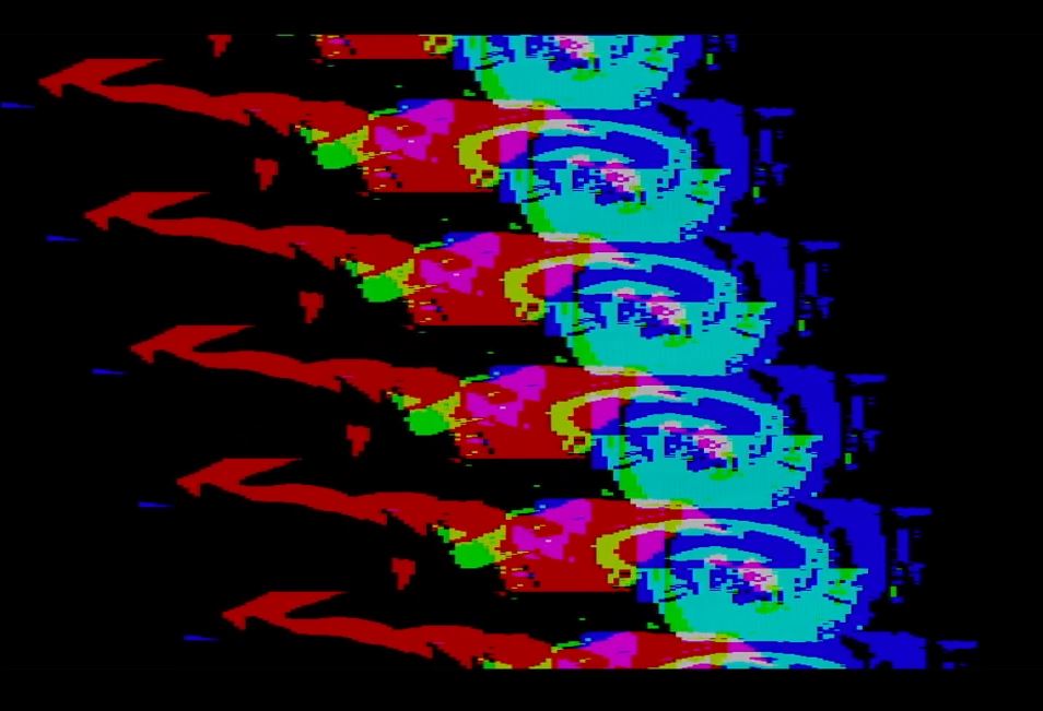
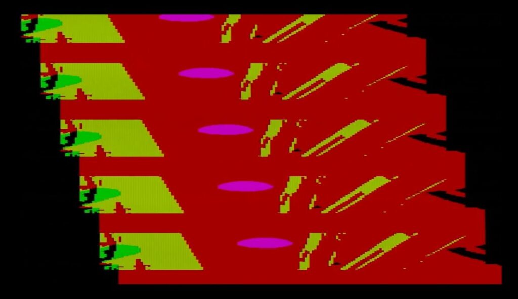
Cool box pixellation effect from https://kevinkripper.com/vsynth :
![]()
![]()
****
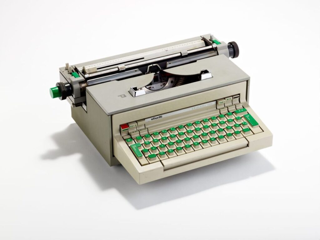
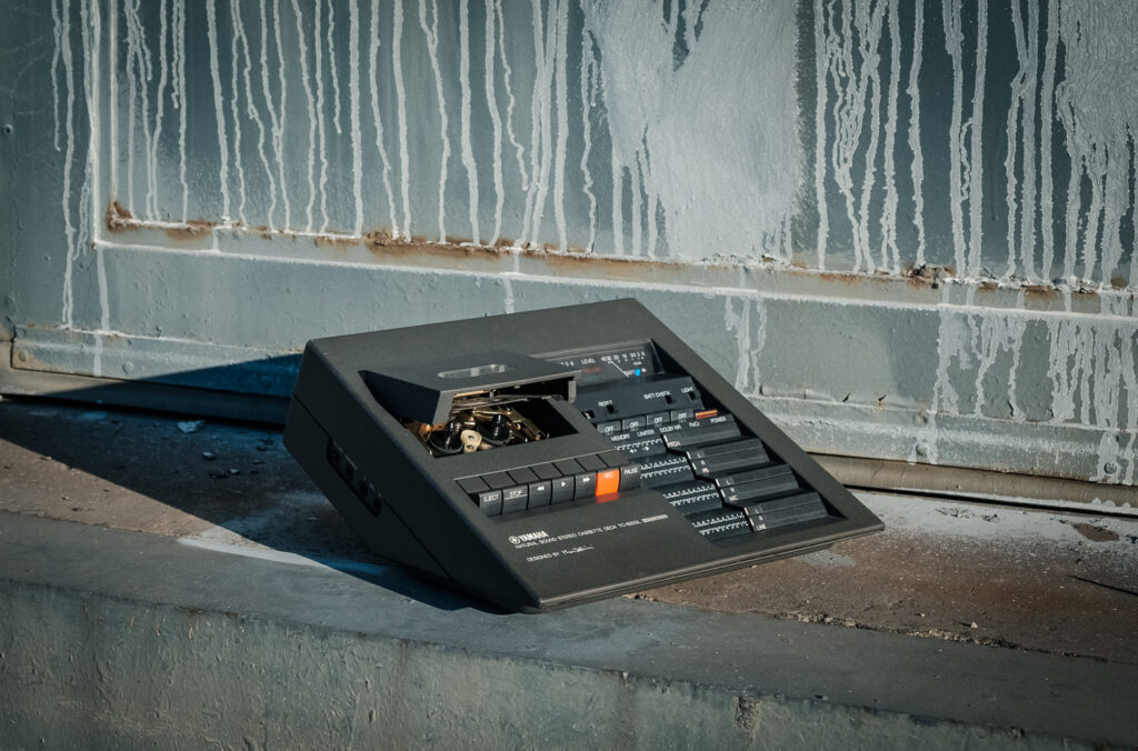
Some nice industrial design from a book about analogue interfaces :
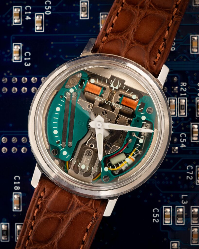
****
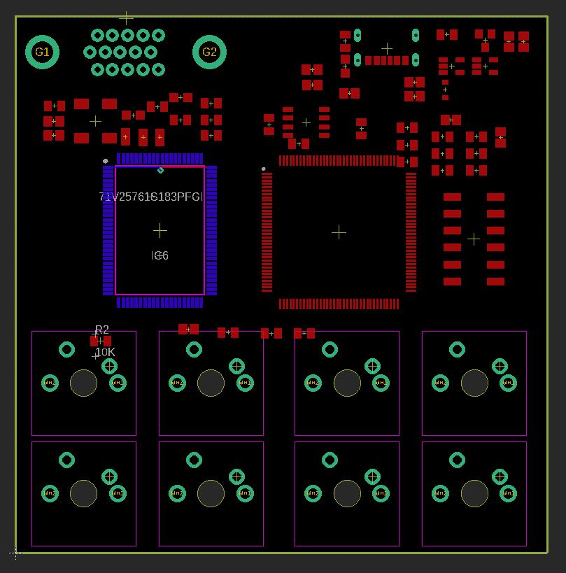
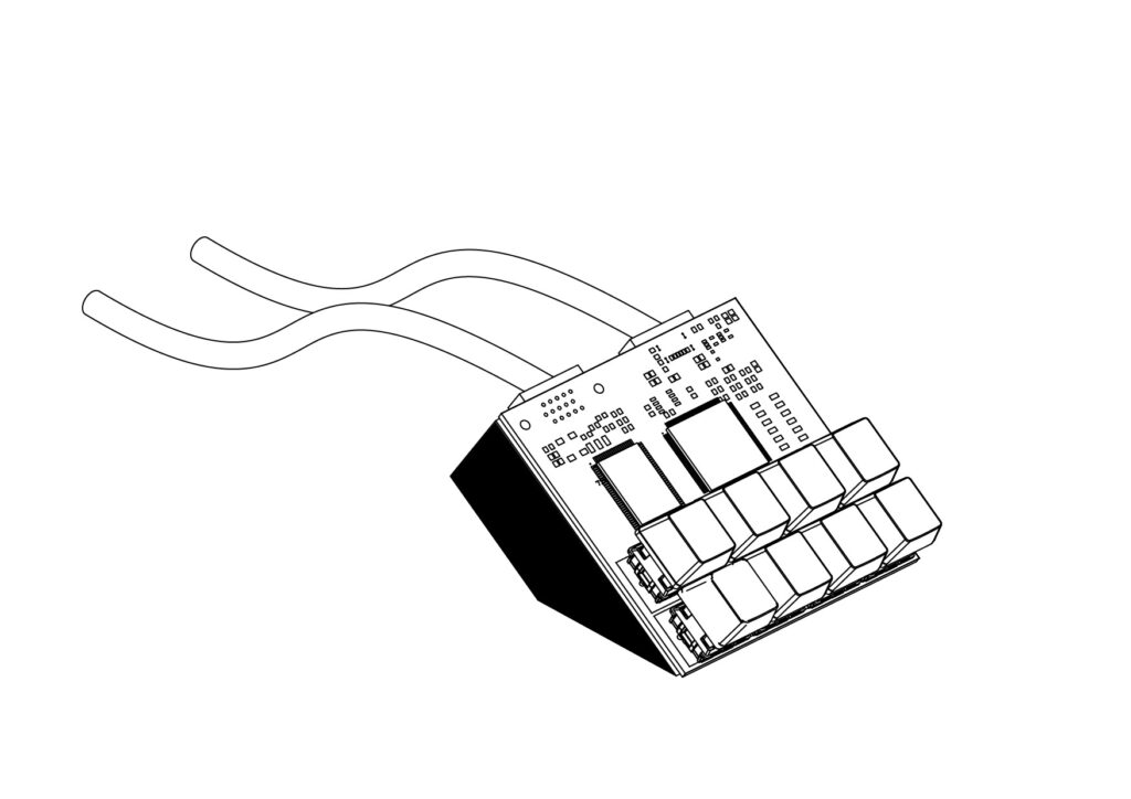
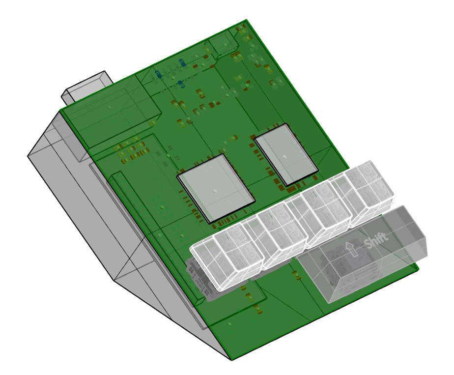
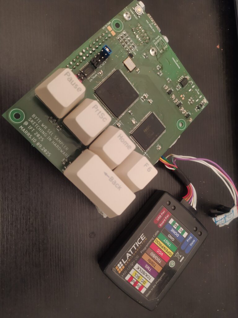
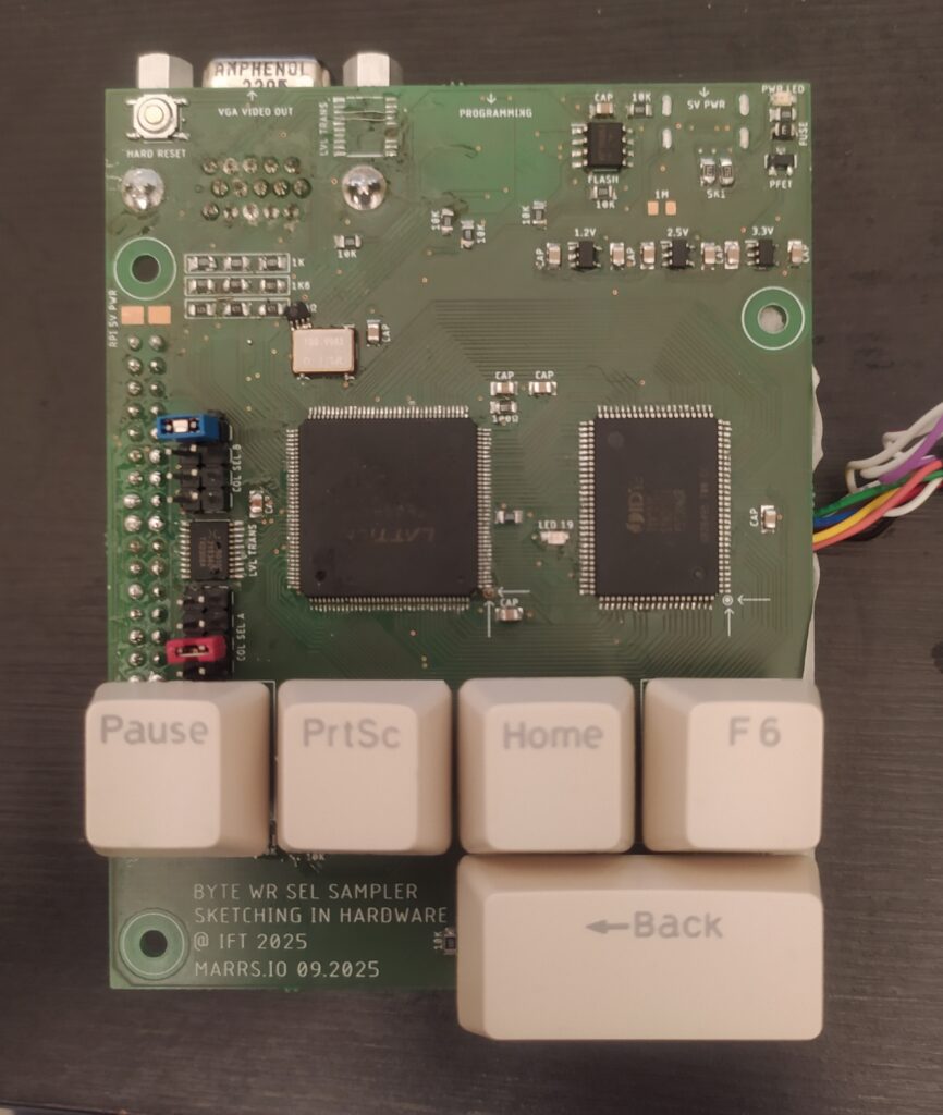
Here’s the final version of the board :
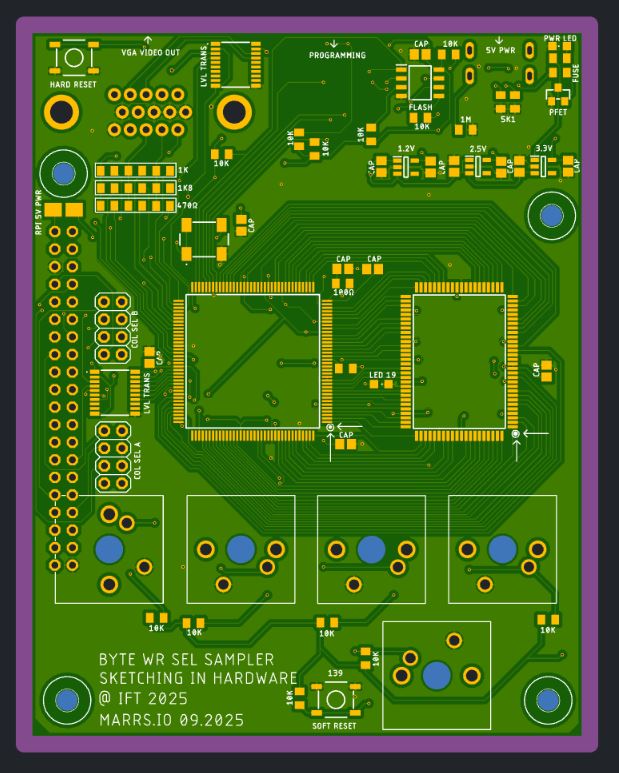
The last minute changes involved mostly taking into account the 2.5V IO voltage of the FPGA and the memory. I had very few IOs to work with and had to take away some keys. I realized that this whole time I’ve been sending VSYNC and HSYNC VGA signals at 3.3V logic levels. I wonder if this will fix the stuttering or the screen turning off. I’ve added a shunt to power the rpi with or without the same supply as the board. I’m excited to try having the connectors on the bottom of the board, and putting everything inside the slanted 3D print. I’m tired of having the rpi cables disconnecting all the time.
******
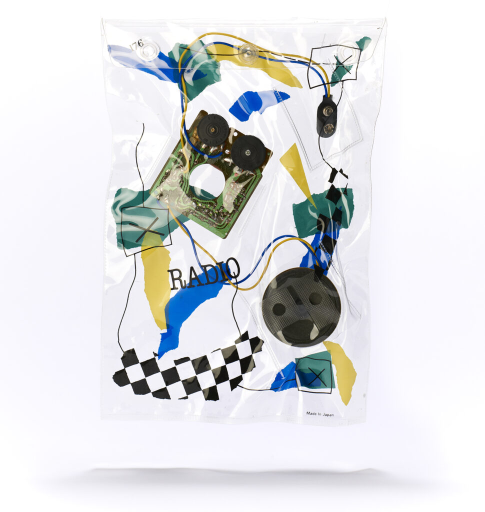
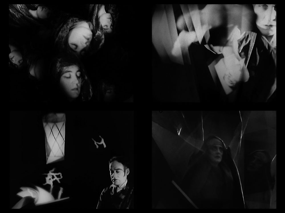
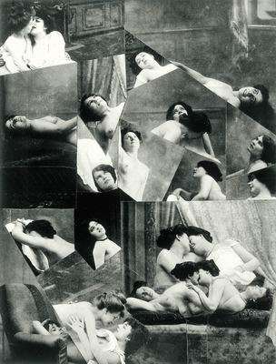
I randomly picked up a book of Luis Buñuel’s surrealist work and found inspiring collages from Dali, Maurice Heine :

****
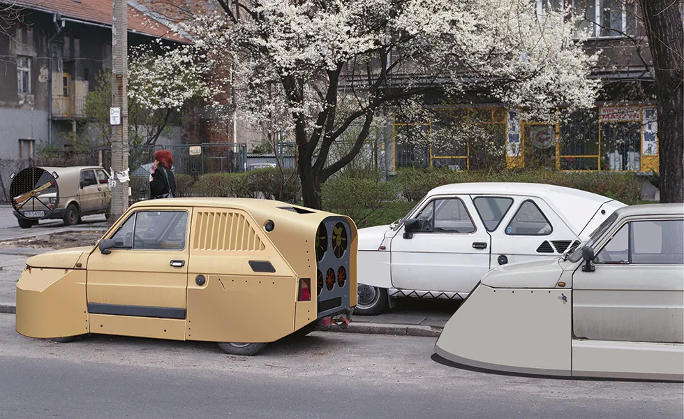
I went to the Cité des Sciences & Industrie, discovered the Aerofiat project where a designermade aerodynamic versions of the Fiat.
There were great expos related to sound, there was a delay tube showing that sound travels at around 360m/second and a bell rung in a vacuum that went silent, a frequency time plot of sound, and an open piano where you could whistle and the strings that were at that resonant frequency would keep vibrating back at you. There was a propogation demo, showing the fact that sound travels in compression and expansion zones.
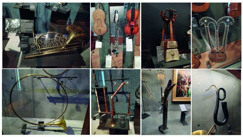
And then the museum of music, where there was beautiful live music and a bunch of strange looking and exquisite instruments :
There was a little expo on Pierre Henry, the musique concrete composer. He treated old recordings like raw materials (samples) that he changed the speed of, added echos, reverbs, superposed tracks. One song was all composed from a single rusty door. I guess that could be a cool workshop activity, to ask students to remix a film.
There was a nice looking synth he had where the flow diagram and different sub systems were drawn on the interface of the machine. I want to do the same thing with a PCB for the sound recorder for the Beaux Arts !
*****
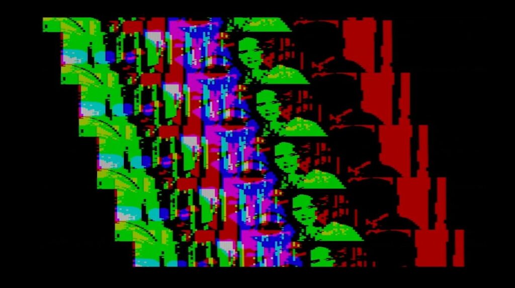
The byte selectable SRAM appears to be working 🙂
Main error from the first version of the board :
- The rpi was upside down, I had to solder 40 female pins on the underside.
- The level shifter before the VGA out which was causing the video to not be legit. I desoldered it and jumped the inputs and outputs.
- The color select pin shunt is too close to the buttons.
I was worried about getting the SRAM working after pouring over the datasheet :
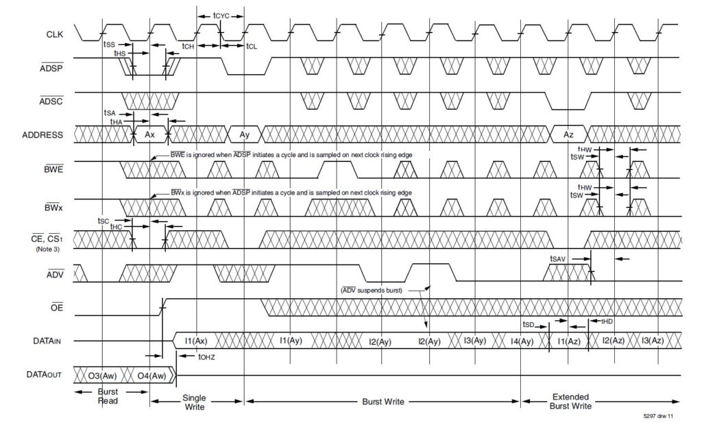
But in the end, it really comes down to ADSP toggling out of phase with the CLK while WE is either HIGH or LOW.
I soldered the solder bridge to power the board with a 5V 3A rpi power supply and so far so good.
Still some things to fix :
- DONE : Try recording perfectly square on the screen using:
address = (h_count>>1)+((v_count>>1)*200); - DONE : Some colors less visible, they should probably each be a mix of RGB.
- DONE : Some channels rarely catch the visible screen, I could use rpi_DEN to fix this.
- It requires an input image that has nice contours for any overlapping images to be legible
- I don’t have a case for when I hit record but don’t push one of the byte enables, and I think that causes the board to crash.
- DONE : try rpi power jumper. EDIT : I had to remove the fuse and PFET in order to power everything from the USB C using a 5V 3A rpi supply.
Here is the verilog :
`default_nettype none

module verilog(

      input wire clk,
      input wire  reset,
      output wire LED,
      //buttons
      input wire  rec,
      input wire  [3:0]key,

      //rpi pins
      input wire  rpi_clk,
      input wire  rpi_DEN,
      input wire  rpi_h_sync,
      input wire  rpi_v_sync,
      input wire  [1:0]rpi_color,

      //SRAM
      output reg [16:0] addr,
      inout wire [31:0] io,
      // inout wire [3:0] iop,
      output wire SRAM_clk,
      output wire cs_0,
      output wire cs_1,
      output wire ce,
      output wire GW,
      output reg BWE,
      output wire BW1,
      output wire BW2,
      output wire BW3,
      output wire BW4,
      output reg ADSP,
      output wire ADSC,
      output wire LBO,
      output wire ADV,

      //VGA OUT
      output wire  h_sync,
      output wire  v_sync,
      output reg  [3:0] r_out,
      output reg  [3:0] g_out,
      output reg  [3:0] b_out
      );

assign BW1 = key[0];
assign BW2 = key[1];
assign BW3 = key[2];
assign BW4 = key[3];
assign SRAM_clk = clk;
assign GW = 1; // active low ; We want to control individual bytes in this test code
assign cs_0 = 1; //active high; chip always selected.
assign cs_1 = 0; //active low ; chip always selected.
assign ce = 0; //active low ; chip always selected.
assign LBO = 0; // Linear burst sequence selected.
assign ADV = 1; //active low; we don't want addresses to auto advance in this test code.
assign ADSC = 1; //active low; we don't want to auto load address registers, we'll use ADSP instead.
assign h_sync = rpi_h_sync;
assign v_sync = rpi_v_sync;
wire [31:0] data_in;
wire [31:0] data_out;

assign data_in[7:0] = (rpi_color[0] == 1'b1) ? 8'b11111111 : 8'b00000000; // color from rpi
assign data_in[15:8] = (rpi_color[0] == 1'b1) ? 8'b11111111 : 8'b00000000; // color from rpi
assign data_in[23:16] = (rpi_color[0] == 1'b1) ? 8'b11111111 : 8'b00000000; // color from rpi
assign data_in[31:24] = (rpi_color[0] == 1'b1) ? 8'b11111111 : 8'b00000000; // color from rpi

reg [31:0] a, b;

assign io[7:0] = (rec==0) ? a[7:0] : 8'bzzzzzzzz;
assign io[15:8] = (rec==0) ? a[15:8] : 8'bzzzzzzzz;
assign io[23:16] = (rec==0) ? a[23:16] : 8'bzzzzzzzz;
assign io[31:24] = (rec==0) ? a[31:24] : 8'bzzzzzzzz;
assign data_out[31:0] = b[31:0];

reg [3:0] counter = 0; //our clock divider

always @(posedge clk) begin

      b[31:0] <= io[31:0];
      a[31:0] <= data_in[31:0];

       if (rec==0) begin // *WRITING* to SRAM (aka recording)

                                            // ADSP should go LOW when SRAM_clk goes HIGH first then HIGH when SRAM_clk goes HIGH on the following cycle...

                                            // ...then, one cycle later, GW should already be LOW to trigger writing

                                            if (counter[0]==1'b0) begin
                                                    ADSP <= 0;
                                                    BWE <= 0;
                                            end

                                            if (counter[0]==1'b1) begin
                                                    ADSP <= 1;
                                                    BWE <= 0;
                                            end
     end

     else begin // *READING* from SRAM (aka playback)

                                            // ADSP should go LOW when SRAM_clk goes HIGH...
                                            //...then, once cycle later, GW should already be HIGH to trigger reading
                                            if (counter[0]==1'b0) begin
                                                     ADSP <= 0;
                                                     BWE <= 1;
                                            end

                                            if (counter[0]==1'b1) begin
                                                     ADSP <= 1;
                                                     BWE <= 1;
                                            end

     end
end

//SRAM address counter
always @(posedge clk) begin

  counter <= counter + 1;

  if (counter[2]) begin

               if(rpi_v_sync) begin // reset the SRAM each time we draw a new frame
                       addr <= 0;
               end
               else begin
                       addr <= addr+1;
               end
  end
end

always @(posedge counter[2]) begin

                              if (rec==1)

                                 begin
                                                                          r_out[0] <= b[7];
                                                                          r_out[1] <= b[7];
                                                                          r_out[2] <= b[31];
                                                                          g_out[0] <= b[15];
                                                                          g_out[1] <= b[15];
                                                                          g_out[2] <= b[15];
                                                                          b_out[0] <= b[24];
                                                                          b_out[1] <= b[24];
                                                                          b_out[2] <= b[31];
                                 end

                              else if (rec==0)

                                 begin
                                                                          r_out[0] <= a[7];
                                                                          r_out[1] <= a[7];
                                                                          r_out[2] <= a[31];
                                                                          g_out[0] <= a[15];
                                                                          g_out[1] <= a[15];
                                                                          g_out[2] <= a[15];
                                                                          b_out[0] <= a[24];
                                                                          b_out[1] <= a[24];
                                                                          b_out[2] <= a[31];
                                 end
end
endmodule