finition of Ur from Oxford Dictionaries :
primitive, original, or earliest.
“urtext”
denoting someone or something regarded as embodying the basic or intrinsic qualities of a particular class or type.
“ur-thespians Patrick Stewart and Ian McKellen”
Reading about cave paintings and ancient sculpture I am realizing that my exploration into the 1970s computer architecture is a kind of fascination with urcomputation.
The eternal question for my project has always been what is being fed into the machines, what it is rereading or rewriting ? Perhaps the answer could be urmedia – ancient art works.
*****
Making a new board to mess with the OV7670 camera. It is a shield for Arduino, which handles the configuration of the camera, and has an FPGA to do the VGA timing and screen buffering.


The idea is that students will be able to experiment with different camera configurations, and do VGA bending they were able to do on the previous trainer board but in place of the rpi they have a camera (which they can point at a screen if they want to capture video). There are three buttons which could control different superposition effects. Compared to the trainer board there is no space for a breadboard (super expensive) but hopefully there are none of the rpi difficulties and it is cheaper (the camera costs very little compared to the rpi).
*********
Students presentations of their drawing machines from the DSAA program :


********
Early digital photographs
…stored in a cylinder drum to “let computers look at images”
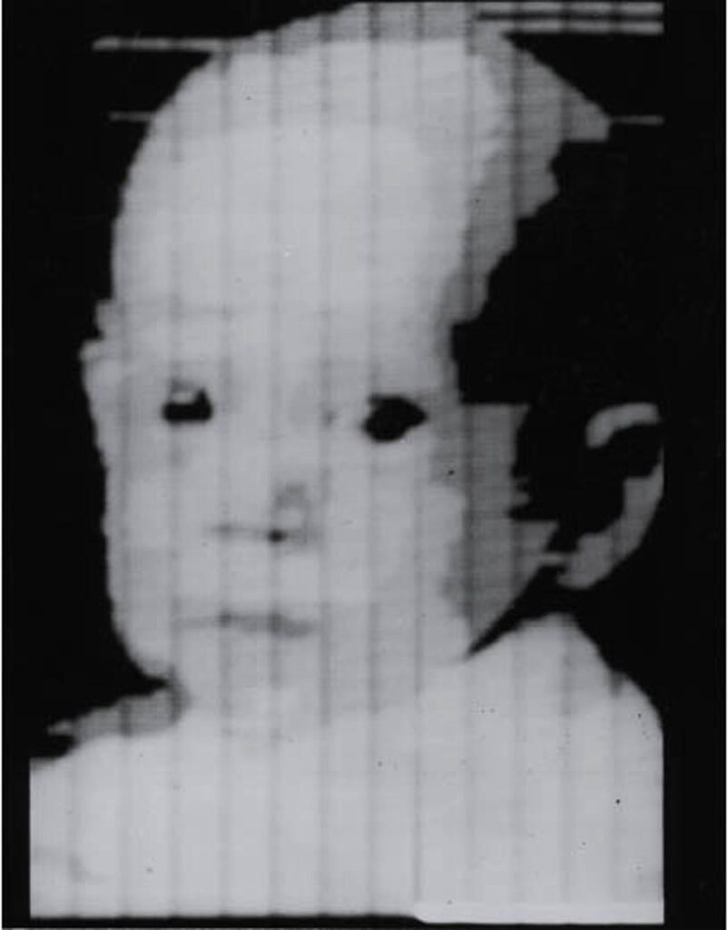
…send from across the Atlantic

…send from space

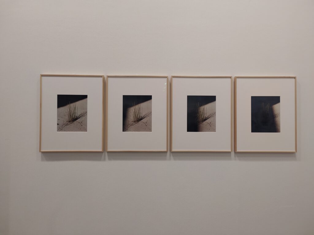
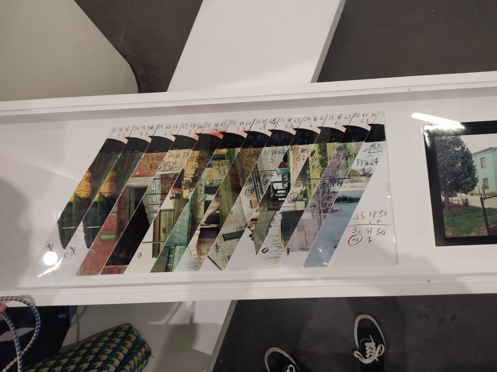
Some highlights from Guido Guidi’s expo at the BAL
Extra long double wide photo :

photo series with changing shadow :
cubic photo :

test strips :
******
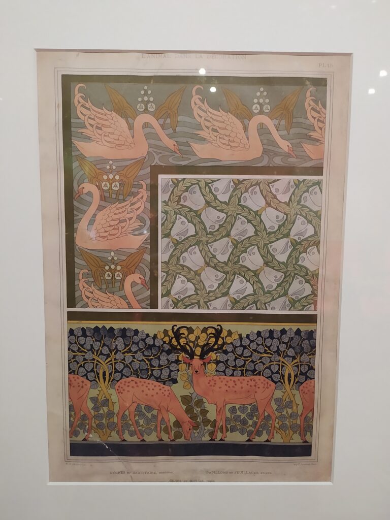
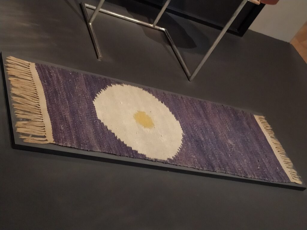
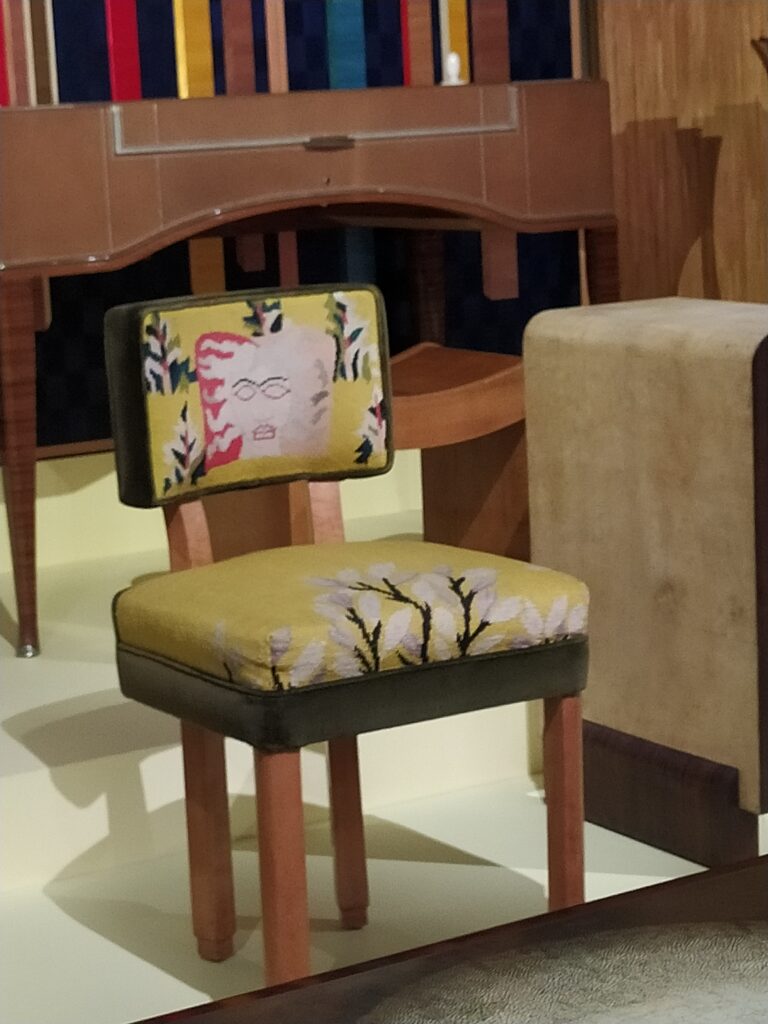
Some highlights from the Art Nouveau expo at the Musée des Arts Décoratifs :
I like the repeating patterns + inset image composition that would be cool to imitate with the synth :
A pixelated fried egg carpet :
A Medusa head chair back :
*****
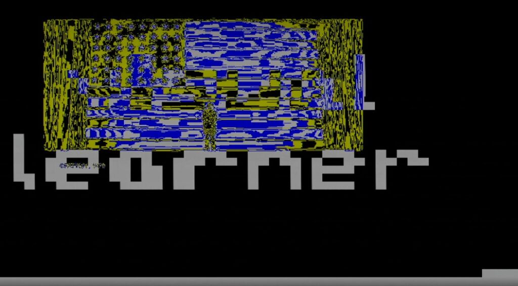
I’ve got simple text working :
//50x37
reg [0:1849] heart =
{
50'b11111111111111111111111111111111111111111111111111,
50'b11111111111111111111111111111111111111111111111111,
50'b11111111111111111111111111111111111111111111111111,
50'b11111111111111111111111111111111111111111111111111,
50'b11111111111111111111111111111111111111111111111111,
50'b11111111111111111111111111111111111111111111111111,
50'b11111111111111111111111111111111111111111111111111,
50'b11111111111111111111111111111111111111111111111111,
50'b11111111111111111111111111111111111111111111111111,
50'b11111111111111111001111111111111111111011111111111,
50'b11111111111111111001111111111111111111011111111111,
50'b11111111111011101001000001011101100111011111111111,
50'b11111111111101101000011110011101010011011111111111,
50'b11111111111100001001000010011001011011011111111111,
50'b11111111111110011001111001010001010011011111111111,
50'b11111111111110011001000011000001000001001111111111,
50'b11111111111111111111111111111111111111111111111111,
50'b11111111111111111111111111111111111111111111111111,
50'b11111111111111111111111111111111111111111111111111,
50'b11111101111111111111111111111111111111111111111111,
50'b11111101111111111111111111111111111111111111111111,
50'b11111101110000110001110000110000111000110100111111,
50'b11111101100110100101100010010010010110010010011111,
50'b11111101100000100100100111110111010000110111111111,
50'b11111100100111100100100111110111010111110111111111,
50'b11111110110001110000100111110111010000110111111111,
50'b11111111111111111111111111111111111111111111111111,
50'b11111111111111111111111111111111111111111111111111,
50'b11111111111111111111111111111111111111111111111111,
50'b11111111111111111111111111111111111111111111111111,
50'b11111111111111111111111111111111111111111111111111,
50'b11111111111111111111111111111111111111111111111111,
50'b11111111111111111111111111111111111111111111111111,
50'b11111111111111111111111111111111111111111111111111,
50'b11111111111111111111111111111111111111111111111111,
50'b11111111111111111111111111111111111111111111111111,
50'b11111111111111111111111111111111111111111111111111
};
reg pixel;
...
address <= (h_count>>4)+((v_count>>4)*25);
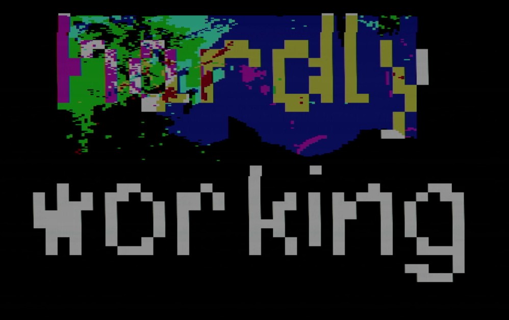
pixel <= heart[address];Here are some more examples :


*****
This machine should not try to be something it’s not. I want to exploit the potential it offers, low level memory manipulation, rather than get lots in technical challenges that aren’t sui generis to the device.
In some way I feel like I’m coming full circle back to these plotter experiments mixing text, fill, and contour that include glitches of the rendering process :
*******
This classic Ti watching hippo hunt :
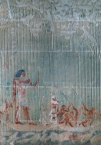
I love the background patterns – the vertical reeds and the underwater diagonal pattern – with people and creatures superimposed.
A nice article about simulating traffic with a simple processor and clever tricks : https://pizzalegacy.nl/blog/traffic-system.html
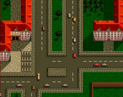
Main tricks : having tiles encode the direction of traffic, cars that go off screen simple respawn on the other side, car speed is fixed based on pixel draw rate, simple test to see if collision next pixel and if so delay for 10 pixels. Tiles are made in such a way that advancing halfway through the tile and then drawing the new car in the subsequent direction of the next tile to complete a 90° turn will always work.
****************
I’ve got horizontal image doubling. Basically, once I reach halfway, I subtract half the screen so it starts drawing again from the left.
if(h_count == 200) begin
     h_count <= h_count - 200;
end
To wiggle horizontally an image (doesn’t work vertically):
h_count <= h_count + 1 + sine;To draw a grid over the screen :
if(h_count%20 == 0 || v_count%10 == 0) begin

   r_out[0] = ~b[7];
   r_out[1] = b[15];
   r_out[2] = b[31];

end
I discovered that the frame from the rpi is actually 400 x 300 and not 800 x 600. This means that I can record two sets of collages and switch between them (can create mini animations like this) :
if(key[4]==1) begin
        addr <= (h_count>>1)+((v_count>>1)*400);
end

else begin
        addr <= 30000 - (h_count>>1)+((v_count>>1)*400);
end
******
Preparing the NO SCHOOL 2026 board. It has to be around 20 euros and I have to make at least 20 of them, so they can’t be too hard to make !
It should output VGA and ideally take an input (VGA, or video from a camera ?). It would be great if it was both a sampler/synth and the VGA trainer board for low level video experiments. The protoboards are expensive though so I’ll probably set it up so it uses an existing protoboard that isn’t integrated into the board.
FPGA Ice40………….6,64 € (for 25+)
Keys………………………1€/piece
OV7670…………………5,01€
VGA female…………..1,22 € (for 25+)
Optional things :
atmega328……………..2,00 €
small SRAM……………1,22 € (IS62C256AL-45TLI-TR)
To fix from the VGA trainer board, I cannot use male headers for connectors ! I’ll need something much more durable like screw terminals (Pluggable Terminal Blocks which are around 30 cents for a two position).
*****
Super understandable verilog implementation of OV7670 camera with the Nexys 4 DDR FPGA (15K LUTs) : https://github.com/westonb/OV7670-Verilog/tree/master
To build this in IceCube I had to start with the file which references the other modules (camera_configure.v) and then I compiled and added each dependent file as it came up as an error. Compiling all of this (minus camera_read) uses 497 or 1280 LUTs. I then added camera_read.v as a module.
Some things I learned from looking at the verilog :
- it uses a ROM to store the OV7670 16bit commands.
- it uses a Finite State Machine to mode between different states (idling, sending, receiving).
- In the hierachy of the files, after camera_configure, OV7670_config.v is at the top, and it uses OV7670_config_ROM and SCCB_interface to store the commands and handle the low level tasks of each message send respectively.
- Once the initialization is complete the done signal is activated. I’ll need to use this to enable frame reading only after the config is complete.
Next would be to add a BRAM to put the down-sampled recorded pixels here and a VGA video output. Some things to keep in mind, it works with a 25MHz clock, the breakout board includes 4.7K resistors pull-up resistors from the SIOD and SIOC pins on the camera to the 3.3V supply, and the author includes a reminder that not every pin on the FPGA can act as clock input (for the PCLOCK coming from the OV7670 in this case). I think the correct type of pin for a clock input is a GB (Global Buffer) pin of which there are 8 in total.
The idea is to now make a test board where the MIT verilog could be tested along with two other options : an atmega328 which I would have to program in-situ, and connections for an Arduino (giving the partipants the ability to also change the camera configuration but requiring everyone to have an Arduino to get the thing functioning). After testing I’ll be able to design a final board that may or may not have all three options.
EDIT : Too lazy to make the atmega328 version and I like that the Arduino allows people to change the camera parameters easily. If all goes well, I’ll make a next version that maybe has SRAM and other features. Because I can understand the MIT 6.111 class FPGA verilog I’m going to add an SD card to this board to see if I can make that work as well (and will take advantage of having Arduino there to also make it work the SD card if the FPGA verilog doesn’t work). This would let me test if I can do away with the rpi and either make my own compressed video put onto an SD card (which would go far to making this a “stand-alone” device), and to test if the camera is an even better solution to produce input video on the fly.
******
UPDATE on OV7670
Took a moment to look at cameras signals on oscilloscope.
- Confirmed that the camera does indeed react to light : oscilloscope triggering on HREF while looking at D[0] while covering sensor or shining light and can see almost direct effect. VS is low for pixels and HREF is high for pixels.
- Tried various different resolutions with OV7670_ARDUINO_CONFIG_RESOLUTION_SELECTION.ino code, I count 320×120 for QQVGA (with 2.36 seconds per frame), 640×240 for QVGA (with 7.36 seconds per frame), and 1400×500 (?) for VGA.
- I have got dual port BRAM working and I can record with rpi clock and playback with FPGA clock for example. I appear to be able to store data from OV7670 camera and then play it back from BRAM but the data is not organized properly.
module ram (din, write_en, waddr, wclk, raddr, rclk, dout);//512x8
parameter addr_width = 15;
parameter data_width = 2;
input [addr_width-1:0] waddr, raddr;
input [data_width-1:0] din;
input write_en, wclk, rclk;
output reg [data_width-1:0] dout;
reg [data_width-1:0] mem [(1<<addr_width)-1:0]
;
always @(posedge wclk) // Write memory.
begin
if (write_en==0) // DON'T FORGET THIS EDIT BECAUSE YOUR KEYS GO TO ZERO WHEN PUSHED !!!
mem[waddr] <= din; // Using write address bus.
end

always @(posedge rclk) // Read memory.
begin
dout <= mem[raddr]; // Using read address bus.
end
endmodule
And to use this module in top.v :
ram ram0(
.din(data_in),
.write_en (rec),
.waddr (waddress),
.wclk (FPGA_counter[3]),
.raddr (raddress),
.rclk (counter[3]),
.dout(data_out)
);
For the NO SCHOOL workshop, thinking of buying rpi zero W v1.1 which I have found available for order.
UPDATE
When I put the OV in VGA mode, I have something that reacts to light and dark, but I still can’t reliably write to the BRAM. I have tried different ways of incrementing the address and clocking the BRAM but they don’t appear to work. I’d like to try SRAM instead, as this will be easier to have two clocks (one for writing and one for reading). I’m also going to try with a logic analyzer so I can have precise counts for pixels and rows.
The logic analyzer (using Logic 2 software for Saleae but with a copy device from amazon) makes quick work on this ! It confirms the VGA mode is 640 x 480 with a pixel clock around 25.5 kHz it takes 15+ seconds to record a full frame.
480 HREFs for a full frame between two VS signals.

…and 640 pixel tics for each HREF :

Here is me suddenly shining a light on the sensor :

Confirmed that the Arduino resolution config gives : QVGA is 640×240 and QQVGA is 320×120.
Looked at the rpi in DPI mode too.
- pixel clock = 50MHz (verified with oscilloscope because not appearing on logic analyzer for some reason)
- DEN (like H SYNC) goes LOW to signal visible pixel area
- There are 600 DEN pics between VSYNC signals (which go high to signal the end of the frame). HSYNCs are kind of messy, they overlap with VSYNC going high, DEN is much better to track. There are around 660 HSYNCs between VSYNCs.
I tried with byte select SRAM and still no luck getting anything intelligible. I’m now going to try to speed up the input clock (XCLK) currently sent by the Arduino to either 25MHz or the max 48MHz and see if that makes life easier. I also forgot to connect GND between the OV7670 and the FPGA when testing earlier !
*********
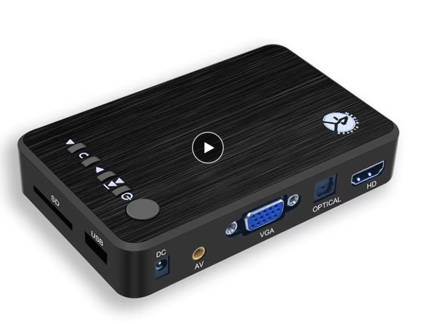
In parallel I’ve been looking in to stand alone media players that output VGA. But it costs 30 euros. Another option would be to get rpis super cheap (can’t find less than 20 euros) but then I have to worry about the rpi version and go through that pain again…
Other options :
- Read a special format on an SD card (MIT simple SD card reader verilog : https://web.mit.edu/6.111/www/f2017/tools/sd_controller.v)
- ESP32 outputting video from SD card.
****
Looked into DLP DMD DLP160APFQT Chip (around 30 euros), but it requires two other chips to get going :
