I have (hopefully) several collaborations coming up next year !
- Circuit bending digital cameras with the Base Photo at the Beaux-Arts
- Solar-powered sound/light/kinetic outdoor sculptures with the Art en situation filliere at the Beaux-Arts
- Voice synthesis with P5js and hopefully in hardware too
TO DO :
- Get OV7670 board fixed (try new FPGA)
Make video (overhead cam + screen) of béchamel making 4 layer recordingTry mirror verilog
*******
Working on the camera bending project. Found inexpensive options on Alibaba for around 6 euros each.
From watching youtube tutorials it appears that most people are intervening where the camera sensors arrives at the camera motherboard. They avoid the power connection and otherwise connect together various parallel data pins and GND together either directly or through a pot in the dirty mixing style. Other options include the ADC. The main difference in cameras is between CCD and CMOS. CCD use capacitors, they are more expensive and analog. CMOS are digital, cheaper and, since the late 2010s, the default as their quality has increased.
For the students I see several places this could go : focusing on the photos themselves, focusing on the making of a brand new camera device using only the circuit board from the original, modifying the original case of the camera and inserting buttons and pots, making videos taken from the live camera data being sent to the screen, or going beyond the electronics and into some neighbouring area (like custom optics, digital image glitching, 3D printing of a new camera case, developing new system like a microscope or IR sensitive camera for astronomy, or using Arduino to automatically take photos).
In the process of the workshop they can learn to use the oscilloscope, multimeter and logic analyser to see what signals are being sent and to identify power pins.
Things left to explore are circuit bending the on board flash memory, ROM and SDRAM. Or possibly the DSP chip itself.
******
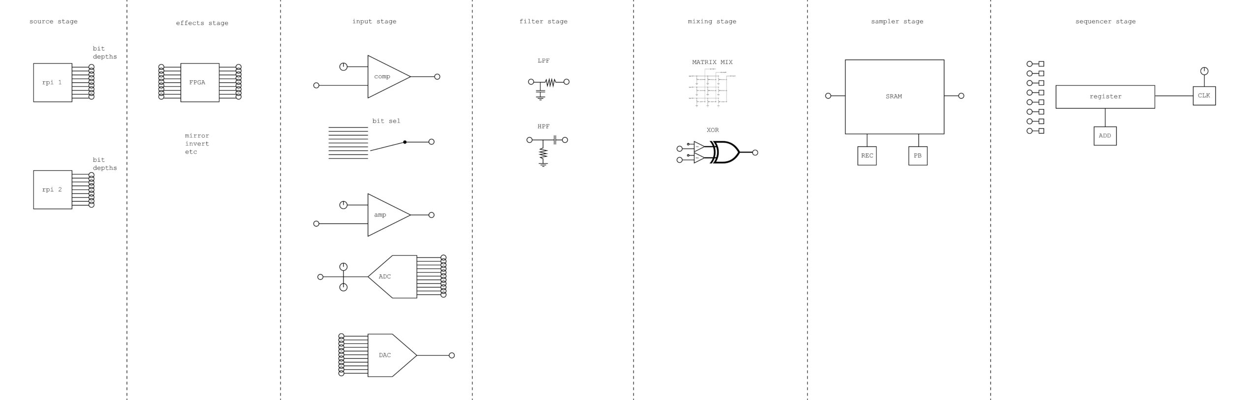
After NO school the idea of doing a video synth that basically incorporates every single circuit I’ve made that was cool :
****
NO school this year was so awesome !
There are some things I would do differently next time though :
- The comparator is a lot of effect for very little setup, should definitely include next time.
- Bring a logic analyzer next time and show them the signals ! This is super useful for demystifying.
- Many had questions regarding the diff bit levels of image on the rpi.
- Same for what constitutes “high frequency” color versus “low freq” for filter part
- I wonder if having Arduino byte beats would have been educational for them, because then they would have made the visuals plus the déformation circuits ?
- Having a print out with the different circuits I asked them to make, perhaps in a little booklet, would have been useful.
- Show people how to put their video files on the rpi SD card using the boot folder !
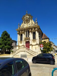
The workshop took place in this chapel :
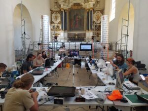
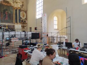
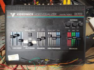
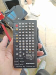
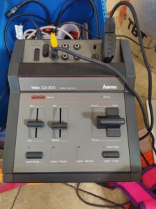
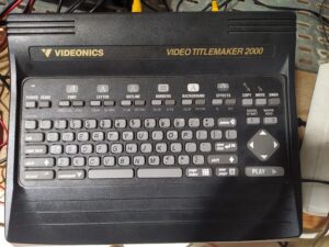
There were plenty of old composite video devices including this video equalizer, mixer, character generator and title maker :
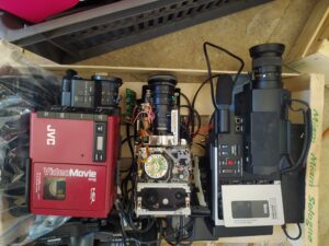
Plenty of old hand-held video tape machines and a digital video camera too :
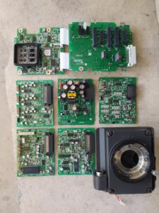
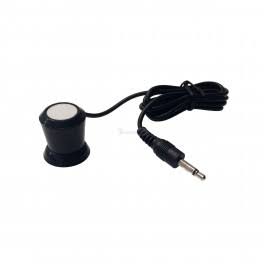
One of the coolest discoveries was this audio pickup coil that you can use to hear all kinds of technological activity going on in a computer, a cell phone, etc.
also :
this hacker manifesto : https://criticalengineering.org/en
Gordon’s projects with RF : https://yugo.at/projects/
Aram Bartholl’s work : https://arambartholl.com/
Alan Warburton : https://alanwarburton.co.uk/
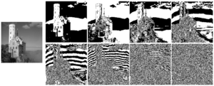
Explaining bit depth of an image visually :

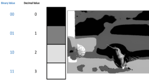
Or from wikipedia :
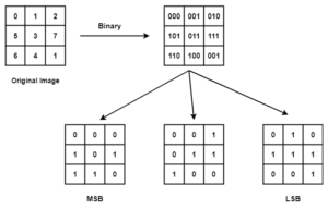
And this diagram showing how the bit planes are generated :
*****
From this blog post about flood fill algorithm : https://tekstien-marginaalien-keskus.aalto.fi/residenssi/heikki/blog/004-december-2/

****
Got vertical mirroring working :
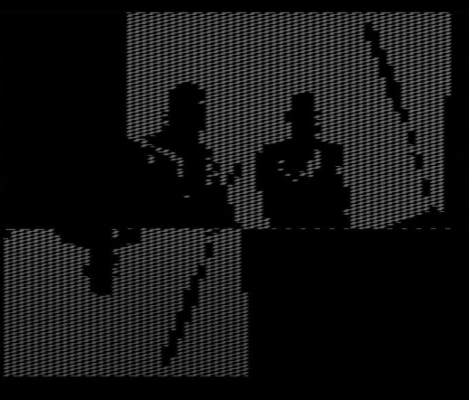
and split screen recording :
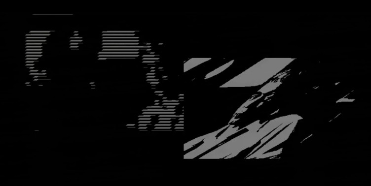
a screen buffer that can be overwritten :
***********
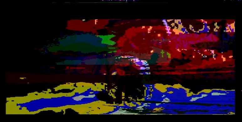
I had some real success today AND’ing recordings with live video that looks great :
******
Pics of the 4ch béchamel in the kitchen :

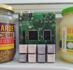
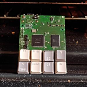
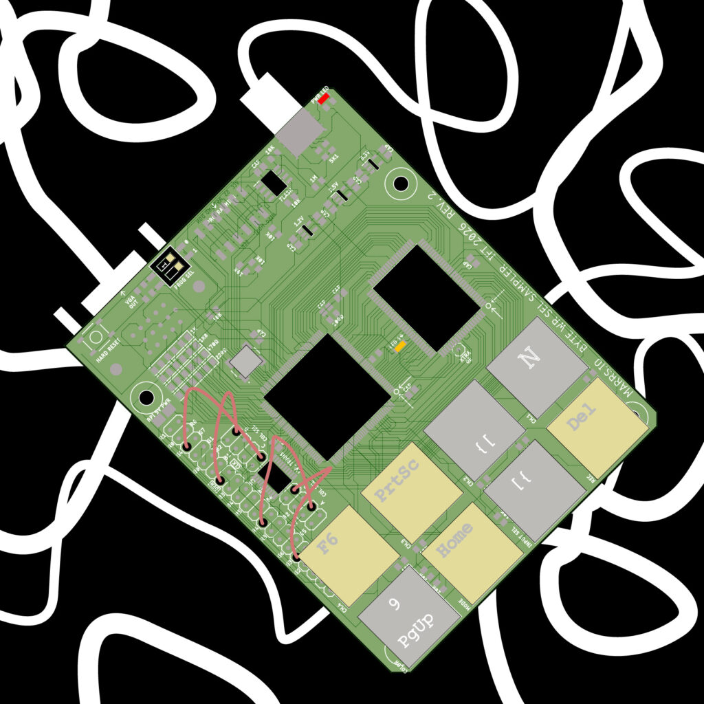
and an illustrator drawing :
****
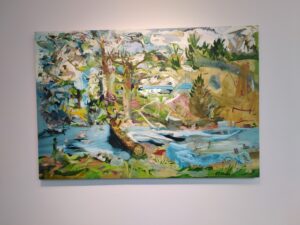
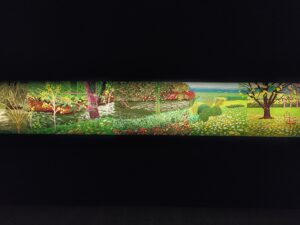
From trip to London :
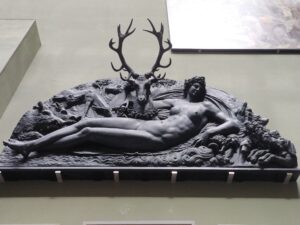
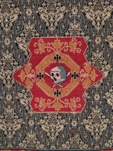
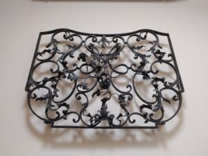
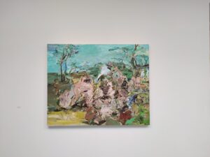
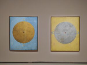
And the grand palais :
****
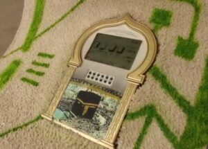
Tracked down Mayssa’s awesome circuit bend project :
And Milan Bergin’s camera :
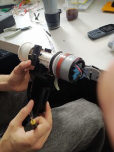
And Annie Turner’s work :
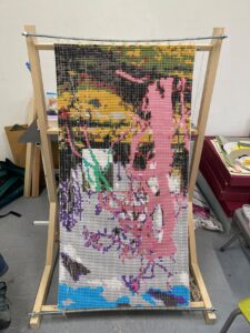
Learned about some new art spaces : La Villa Belleville (https://www.villabelleville.org/) and DOC! (https://doc.work/)
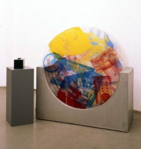
Rauschenberg’s work with EAT :
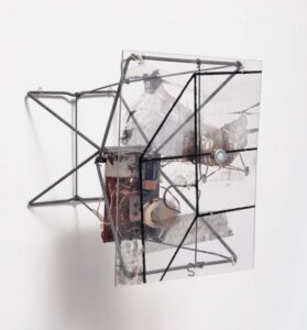
And Haroon Mirza’s solar power artworks :
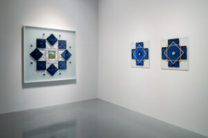
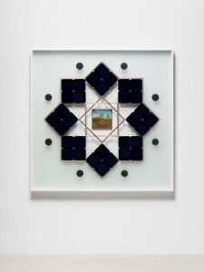
Beautiful article showing the visible colors and how the screen can’t show certain colors (basically certain kinds of blue green are not displayable on the screen) : https://moultano.wordpress.com/2026/06/19/where-to-find-the-colors-your-screen-cant-show-you/

And a truly incredible investigation to recreate test images for video broadcast :

****
Check out this debug tool for the Play Station which shows the VRAM (from https://www.copetti.org/writings/consoles/playstation/):
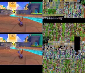
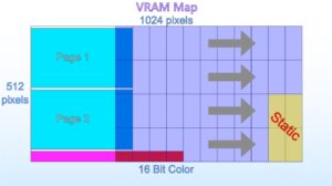
There is a double screen buffer on the left and on the right are CLUTs and textures. Here’s a map showing how the VRAM is divided :
Also interesting that the Play Station has a chip to quickly decompress images stored in a custom format. Could I make my own kind of simple Run length encoding compression ?
Looking at sprites there are also flipbooks, collections of sprites that can be used to form animations (such as a candle flickering).
Could I experiment with applying textures to zones ? Could I make “functions” in verliog to draw lines, triangles and rectangles ?
*****
Some things to try :

A color LUT which can be randomly generated and regenerated at the push of a button. With four bits for each color, I have 12 bit depth and would need 4096-1 entries in the table (?). I am following this tutorial https://projectf.io/posts/display-signals/ and using this CLUT https://github.com/projf/projf-explore/blob/main/lib/res/palettes/antiquity16_4b.mem.
I had a tough time getting IceCube2 to accept this idea. Hard to instantiate memory, though having reset trigger loading memory could have been an option. I went for an 16 element array of 12 bit values like this :
 //CLUT
reg [11:0] CLUT[0:15] =

{
12'h222,
12'h322,
12'h432,
12'h743,
12'hB75,
12'hFA7,
12'hFC8,
12'h675,
12'h995,
12'h789,
12'h9AB,
12'hE65,
12'hF87,
12'hD63,
12'hEA3,
12'hFEA
};
But using data_out from the BRAM as an index didn’t work. I switches to a switch case which did work but is less easily interchangable for a new palette :
assign r_out = (rec==0) ? rpi_color : colors[3:0];
assign g_out = (rec==0) ? rpi_color : colors[7:4];
assign b_out = (rec==0) ? rpi_color : colors[11:8];

always@(*) begin
case(data_out)
4'b0000: colors = 12'h222;
4'b0001: colors = 12'h322;
4'b0010: colors = 12'h432;
4'b0011: colors = 12'h743;
4'b0100: colors = 12'hB75;
4'b0101: colors = 12'hFA7;
4'b0110: colors = 12'hFC8;
4'b0111: colors = 12'h675;
4'b1000: colors = 12'h995;
4'b1001: colors = 12'h789;
4'b1010: colors = 12'h9AB;
4'b1011: colors = 12'hE65;
4'b1100: colors = 12'hF87;
4'b1101: colors = 12'hD63;
4'b1110: colors = 12'hEA3;
4'b1111: colors = 12'hFEA;
default: colors = 12'h222;
endcase
end
Nice sunset color palette though :

I can only get the memory working with the same values for the 15×2 array. But I now have three palettes and can change between them with key presses !

***
Got a tour of the engraving workshop at the BA and saw them making multiple color woodblock prints similar to this :

The workshop head kept referring to the medium that stores the information. Could I do something similar with my four SRAM blocks ?
***
A kind of numbered grid on the edges of the screen :

I can already put text from a font on screen, this would just involve adding numbers putting other images behind the text.
A mirror effect :

Recentering the camera on the edge of the screen :

rotating images :

bit blitting parts of images to create superimposed windows:

Different resolutions on the same screen :

****

Some VGA hardware diagrams showing different sub systems like a sequencer, the sync gen, and multiple RAM planes. Would be cool to recreate this explicitly in FPGA and then prod each interface and show the results.
I have got BRAM working with simple VGA sync generated by the FPGA and rpi/OV camera input. Changing the clocking frequency for the address incrementing changes the shape of the pixels.


But so far from the camera I’m only getting noise. I believe this is because I’m naively trying to send a single bit at a time and the OV camera appears to send RGB colors in a two byte package. I’ll need to test on the new board.


I had many verilog struggles, the worst of which was causing the BRAM not to instantiate and various pins to be ignored.
ram ram0(
.din(data_in),
.write_en (rec),
.waddr (waddress),
.wclk (counter[0]),
.raddr (raddress),
.rclk (clk_div[1]),
.dout(data_out)
);
If you select clock divisions for rclk and wclk that are too slow, all kinds of seemingly buggy behaviour takes place. I only got to this answer by rebuilding the vga sync and BRAM from scratch several times.
I learned that you can in fact divide by whole numbers instead of bit shifting to divide :
raddress <= (h_counter/3)+((v_counter/3)*213);The logic analyzer was essential for being able to see the signals of the rpi and the OV camera. The oscilloscope also helped reveal that the level shifter (along with longish breadboard wires) on the board was interfering with the OV data and clock signals.
The documentation for the OV7670 camera and the registers is a nightmare for me to understand. I think I will not use this for a kit for NO SCHOOL and instead get rpi zero W1.1 and skip the board all together and just have a collection of useful components.
****
From the musée de la chasse et de la nature, this beautiful chest of drawers each with a seperate scene :

***
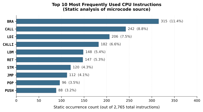
Just learned from this post https://baltazarstudios.com/calculator-cpu/ that “20% of the instructions in a typical program accounted for about 80% of the execution” and that this is how we got RISC instruction sets.
*****
Trying to get character display working. Found great site with 8×8 fonts here https://int10h.org/oldschool-pc-fonts/fontlist/font?ibm_bios . Couldn’t figure out how to get nice clear binary display from these font files though so eventually landed on this : https://gist.github.com/rothwerx/700f275d078b3483509f and formatted them with Notepad++:
reg [0:63] a =
{
8'b00000000,
8'b00000000,
8'b01111000,
8'b00001100,
8'b01111100,
8'b11001100,
8'b01110110,
8'b00000000
};

reg [0:63] b =
{
8'b11100000,
8'b01100000,
8'b01100000,
8'b01111100,
8'b01100110,
8'b01100110,
8'b11011100,
8'b00000000
};
address <= (h_counter/80)+((v_counter/60)*8);

address <= (h_counter[5:3])+((v_counter[5:3])*8);
reg char;
reg[14:0] address;
wire [5:0] short_address;

assign short_address = address[5:0];

wire [2:0]concat;
assign concat = {v_counter[4:3],h_counter[3]};

always @(*)
begin
case (cell_counter)
3'b000 : char = a[short_address];
3'b001 : char = b[short_address];
3'b010 : char = c[short_address];
3'b011 : char = d[short_address];
3'b100 : char = e[short_address];
3'b101 : char = f[short_address];
3'b110 : char = g[short_address];
3'b111 : char = h[short_address];
default : char = i[short_address];
endcase
end

reg [2:0]cell_counter;

//10 by 7.5 copies of the letter 'a'
always @(posedge clk_div[1]) begin

address <= (h_counter[5:3])+((v_counter[5:3])*8);

cell_counter <= (h_counter/64) + ((v_counter/64)*10);
end

***
Different parameters of a raster (made using this site https://www.uwarp.design/pixel-text):
- pixel gap


- pixel shape


- pixel size
***
Nice article https://www.quantamagazine.org/how-the-bird-eye-was-pushed-to-an-evolutionary-extreme-20260513/ talking about how bird’s eyes work. Mentioning that nature acts more like a tinkerer than an inventor :
“Evolution is not really like an inventor; it acts more like a tinkerer,” he said, citing a 1977 essay, “Evolution and Tinkering (opens a new tab),” by the French biologist François Jacob. “It takes parts that have existed long before, and it recombines, reinvents, and reshapes.”
***
0: (src + dst) / 2
1: src + dst
2: dst - src
3: dst + src/4
****
I soldered the 0V7670 board using the end of supplies I had :


and with the camera plugged in :

Sits nicely atop the Arduino but I placed the keys a smidgen too close together for keycaps to sit on them without rubbing together. So far it doesn’t program, have tried two flash ICs and will continue trouble shooting tomorrow.
I replaced the flash IC twice, resoldered the oscillator, and went around the header and the FPGA to remelt pins. Still no luck. I may have to replace the FPGA next even though the soldering process was extra smooth and it was brand new. I’ve double checked PLL power, the 2.5V diode pin, the 1.2V and 3.3 power points on the board and they look normal. The 1.2V LDO is working. Hmmmm.
I resoldered the entire board with fresh components and get the same error. Currently thinking that it could be my soldering iron is too hot ? Checked the clock, voltage levels, shorts, everything is normal. Still getting the ID check error when I try to program.