For a change, this is a video of me working on the boards for this project:
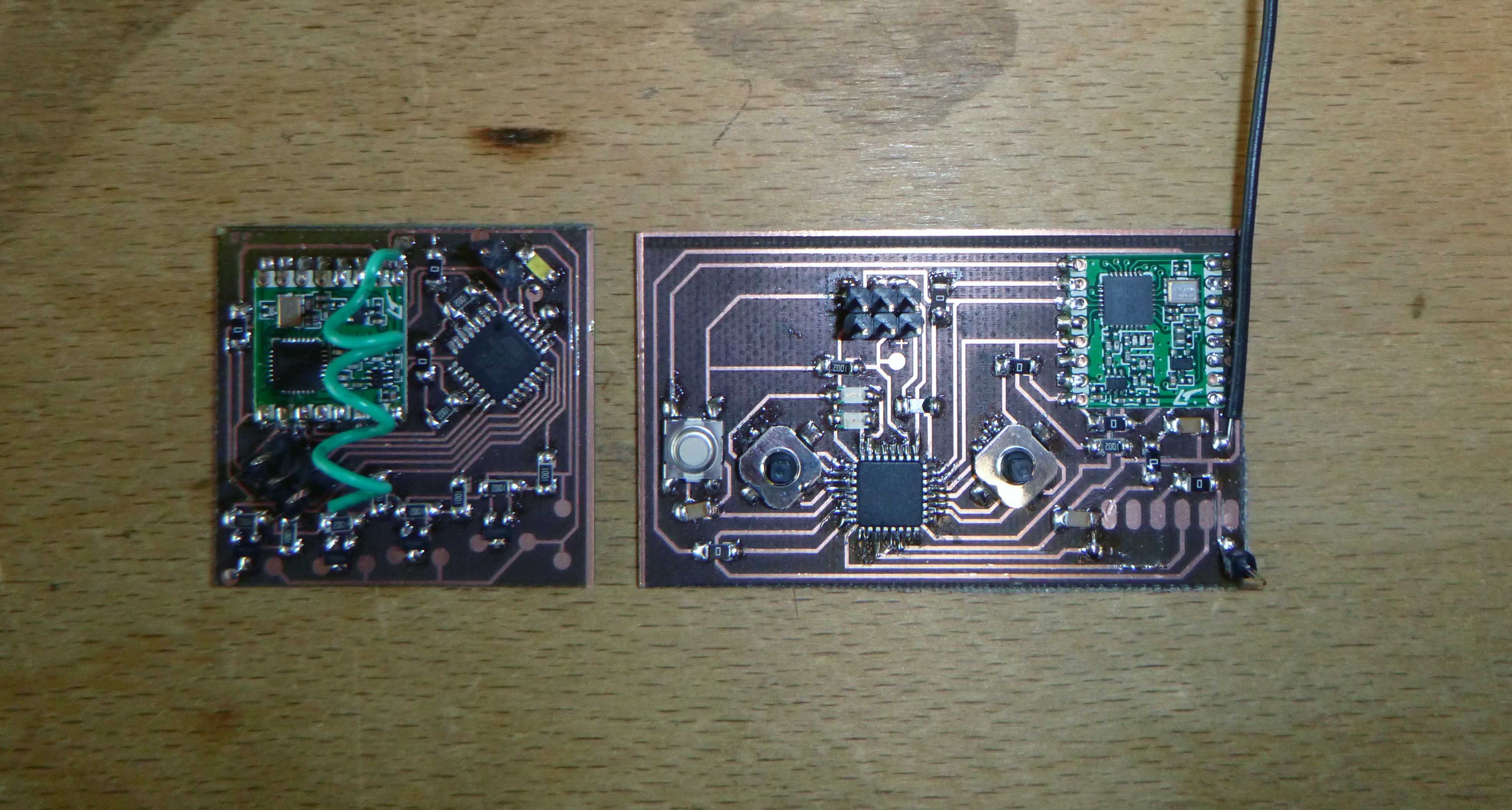
Radios are working, I’m struggling with the best way to poll the joysticks. I think I need to use Pin Change Interrupts (Interrupts for pins other than those dedicated for interrupting). The other option is just to have polling:
if (UP == HIGH){ Send(UP);}
if (DOWN == HIGH){ Send(DOWN);}
etc.
*Later realized that I messed this up, what I want is to check if the pin is LOW (i.e. if it is connected to ground and not internally pulled up) and then have an else at the end which turns to HIGH.
*I forgot to put pull-up resistors on the actual board so I used the avr’s internal ones. In arduino you do this like so:
pinMode(A0, INPUT_PULLUP);
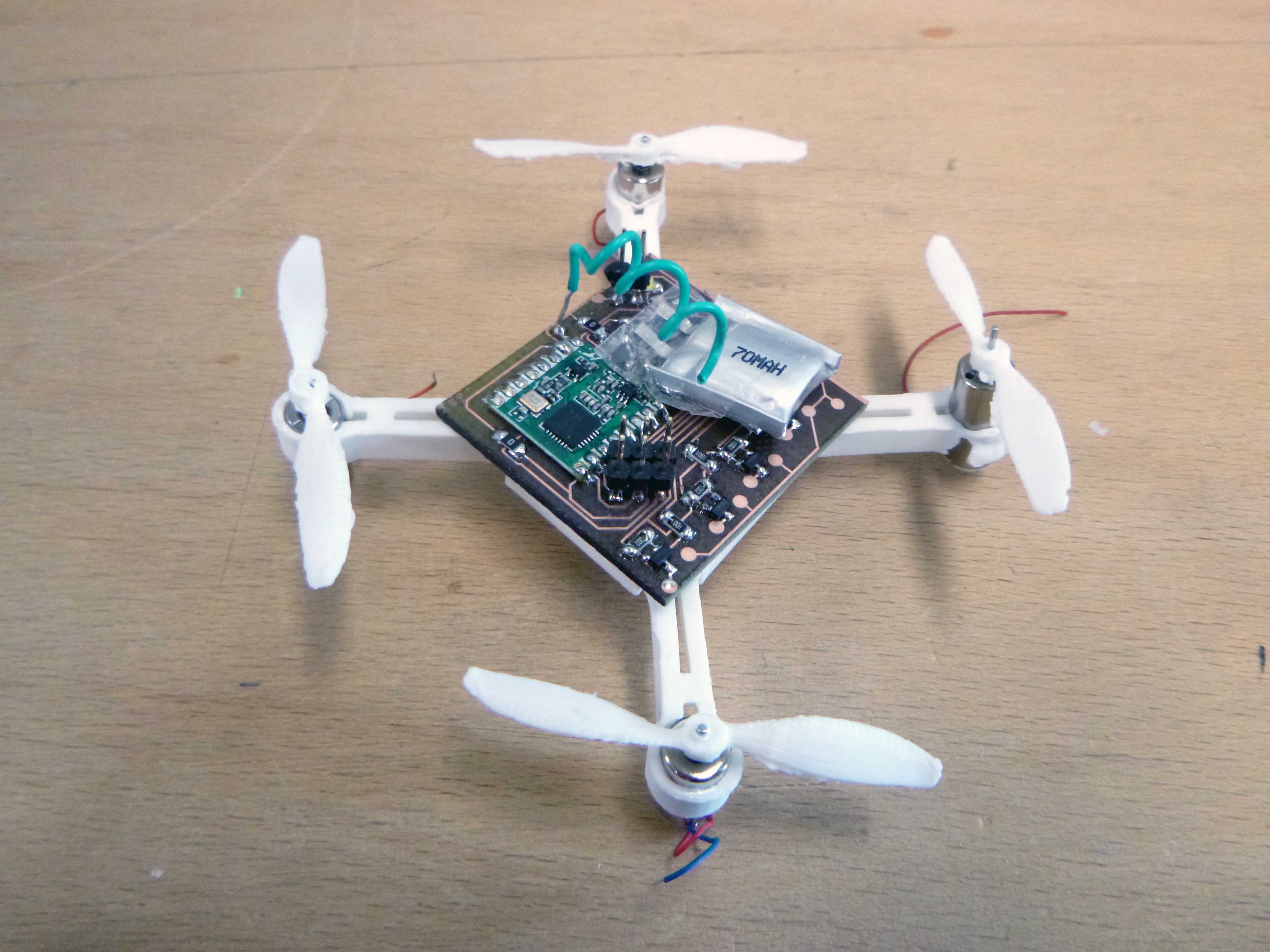
I reprinted the drone frame with .1mm extra space around the circle and now the motors fit snuggly.
Dissapointed that the joysticks only register an up or down when also pushed down…
Here is the joystick sending code:
********************************************************************************
// RFM69HCW Example Sketch
// Send serial input characters from one RFM69 node to another
// Based on RFM69 library sample code by Felix Rusu
// http://LowPowerLab.com/contact
// Modified for RFM69HCW by Mike Grusin, 4/16
// This sketch will show you the basics of using an
// RFM69HCW radio module. SparkFun’s part numbers are:
// 915MHz: https://www.sparkfun.com/products/12775
// 434MHz: https://www.sparkfun.com/products/12823
// See the hook-up guide for wiring instructions:
// https://learn.sparkfun.com/tutorials/rfm69hcw-hookup-guide
// Uses the RFM69 library by Felix Rusu, LowPowerLab.com
// Original library: https://www.github.com/lowpowerlab/rfm69
// SparkFun repository: https://github.com/sparkfun/RFM69HCW_Breakout
// Include the RFM69 and SPI libraries:
#include <RFM69.h>
#include <SPI.h>
// Addresses for this node. CHANGE THESE FOR EACH NODE!
#define NETWORKID 0 // Must be the same for all nodes (0 to 255)
#define MYNODEID 1 // My node ID (0 to 255)
#define TONODEID 2 // Destination node ID (0 to 254, 255 = broadcast)
// RFM69 frequency, uncomment the frequency of your module:
//#define FREQUENCY RF69_433MHZ
#define FREQUENCY RF69_915MHZ
// AES encryption (or not):
#define ENCRYPT true // Set to “true” to use encryption
#define ENCRYPTKEY “TOPSECRETPASSWRD” // Use the same 16-byte key on all nodes
// Use ACKnowledge when sending messages (or not):
#define USEACK true // Request ACKs or not
// joystick and leds
#define LED1 A0 // LED positive pin
#define UP1 A2//
#define LEFT1 A3//
#define RIGHT1 A4//
#define DOWN1 A5//
#define LED2 A1 // LED positive pin
#define UP2 8//
#define LEFT2 9//
#define RIGHT2 7//
#define DOWN2 6//
// Create a library object for our RFM69HCW module:
RFM69 radio;
void setup()
{
// leds and joystick init
pinMode(LED1,OUTPUT);
pinMode(LED2,OUTPUT);
pinMode(UP1,INPUT_PULLUP);
pinMode(LEFT1,INPUT_PULLUP);
pinMode(RIGHT1,INPUT_PULLUP);
pinMode(DOWN1,INPUT_PULLUP);
pinMode(UP2,INPUT_PULLUP);
pinMode(LEFT2,INPUT_PULLUP);
pinMode(RIGHT2,INPUT_PULLUP);
pinMode(DOWN2,INPUT_PULLUP);
// Initialize the RFM69HCW:
radio.initialize(FREQUENCY, MYNODEID, NETWORKID);
radio.setHighPower(); // Always use this for RFM69HCW
// Turn on encryption if desired:
if (ENCRYPT)
radio.encrypt(ENCRYPTKEY);
}
void loop()
{
//setting up variables for button states
int sensorVal0 = digitalRead(UP1);
int sensorVal1 = digitalRead(LEFT1);
int sensorVal2 = digitalRead(RIGHT1);
int sensorVal3 = digitalRead(DOWN1);
int sensorVal4 = digitalRead(UP2);
int sensorVal5 = digitalRead(LEFT2);
int sensorVal6 = digitalRead(RIGHT2);
int sensorVal7 = digitalRead(DOWN2);
// SENDING
// In this section, we’ll gather serial characters and
// send them to the other node if we (1) get a carriage return,
// or (2) the buffer is full (61 characters).
// If there is any serial input, add it to the buffer:
char buffer[5] = “z”;
//BUTTON READING AND SENDING
if (sensorVal0 == LOW) {
buffer[0] = ‘a’;
digitalWrite(LED2, HIGH);
}
else if (sensorVal1 == LOW) {
buffer[0] = ‘b’;
digitalWrite(LED2, HIGH);
}
else if (sensorVal2 == LOW) {
buffer[0] = ‘c’;
digitalWrite(LED2, HIGH);
}
else if (sensorVal3 == LOW) {
buffer[0] = ‘d’;
digitalWrite(LED2, HIGH);
}
else if (sensorVal4 == LOW) {
buffer[0] = ‘e’;
digitalWrite(LED1, HIGH);
}
else if (sensorVal5 == LOW) {
buffer[0] = ‘f’;
digitalWrite(LED1, HIGH);
}
else if (sensorVal6 == LOW) {
buffer[0] = ‘g’;
digitalWrite(LED1, HIGH);
}
else if (sensorVal7 == LOW) {
buffer[0] = ‘h’;
digitalWrite(LED1, HIGH);
}
else {
buffer[0] = ‘z’;
digitalWrite(LED2, LOW);
digitalWrite(LED1, LOW);
}
// END OF BUTTON STUFF
if(buffer[0]!=’z’)
{
static int sendlength = 3;
radio.sendWithRetry(TONODEID, buffer, sendlength);
}
}
********************************************************************************
And here is the receiver code:
*********************************************************************************
// RFM69HCW Example Sketch
// Send serial input characters from one RFM69 node to another
// Based on RFM69 library sample code by Felix Rusu
// http://LowPowerLab.com/contact
// Modified for RFM69HCW by Mike Grusin, 4/16
// This sketch will show you the basics of using an
// RFM69HCW radio module. SparkFun’s part numbers are:
// 915MHz: https://www.sparkfun.com/products/12775
// 434MHz: https://www.sparkfun.com/products/12823
// See the hook-up guide for wiring instructions:
// https://learn.sparkfun.com/tutorials/rfm69hcw-hookup-guide
// Uses the RFM69 library by Felix Rusu, LowPowerLab.com
// Original library: https://www.github.com/lowpowerlab/rfm69
// SparkFun repository: https://github.com/sparkfun/RFM69HCW_Breakout
// Include the RFM69 and SPI libraries:
#include <SPI.h>
#include <RFM69.h>
// Addresses for this node. CHANGE THESE FOR EACH NODE!
#define NETWORKID 0 // Must be the same for all nodes
#define MYNODEID 2 // My node ID
#define TONODEID 1 // Destination node ID
// RFM69 frequency, uncomment the frequency of your module:
//#define FREQUENCY RF69_433MHZ
#define FREQUENCY RF69_915MHZ
// AES encryption (or not):
#define ENCRYPT true // Set to “true” to use encryption
#define ENCRYPTKEY “TOPSECRETPASSWRD” // Use the same 16-byte key on all nodes
// Use ACKnowledge when sending messages (or not):
#define USEACK true // Request ACKs or not
// Packet sent/received indicator LED (optional):
#define LED 1 // LED positive pin
// Create a library object for our RFM69HCW module:
RFM69 radio;
void setup()
{
// Open a serial port so we can send keystrokes to the module:
pinMode(LED,OUTPUT);
digitalWrite(LED,LOW);
radio.initialize(FREQUENCY, MYNODEID, NETWORKID);
radio.setHighPower(); // Always use this for RFM69HCW
if (ENCRYPT)
radio.encrypt(ENCRYPTKEY);
}
void loop()
{
// RECEIVING
// In this section, we’ll check with the RFM69HCW to see
// if it has received any packets:
if (radio.receiveDone()) // Got one!
{
// Print out the information:
// The actual message is contained in the DATA array,
// and is DATALEN bytes in size:
// char message = radio.DATA[0];
// RSSI is the “Receive Signal Strength Indicator”,
// smaller numbers mean higher power.
// Send an ACK if requested.
// (You don’t need this code if you’re not using ACKs.)
if (radio.ACKRequested())
{
radio.sendACK();
}
Blink(LED,10);
}
}
void Blink(byte PIN, int DELAY_MS)
// Blink an LED for a given number of ms
{
digitalWrite(PIN,HIGH);
delay(DELAY_MS);
digitalWrite(PIN,LOW);
}
*********************************************************************************
Now just waiting for some new pager motors to arrive…
I’ve got some old drones which I have taken apart for batteries, motors and propellers. The motors are slightly larger to I have redesigned the 3D print. The motors are 8.5mm in diameter and I found that subtracting with an 8.8mm cylinder make for the snuggest fit.