

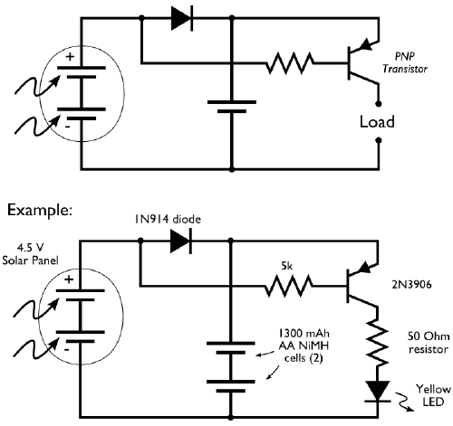
 …and with a joule thief:
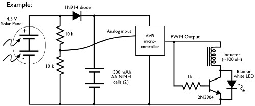
…and with a microcontroller:
…and just to turn on a battery at night:

At the moment the solar charging circuit works well on it’s own, you can see the effect of me covering the solar panel with my hand and the low signal it produces in the scope trace below. The problem is that even in sleep mode with the BOD disactivated the Attiny84 is still drawing too much current for the small solar panel to cover. One easy solution would be a larger solar panel. I will try disactivating more subsystems in the attiny too.

Moving over to the Attiny2313 things are looking better, with BOD enabled and set to 1.7
The next step for this circuit is to have the microchip check the voltage of the supercapacitor while drawing as little current as possible. Jeelabs has some cool articles on this subject here: https://jeelabs.org/2013/05/16/measuring-the-battery-without-draining-it/.
Attiny Power Saving
-Running the clock at 1MHz -Running at a lower voltage (AttinyVs can run on 1.8V, non-Vs can go to 2.7V) -Turn off Brown Out Detection (BOD) -Turn off ADC (in the Power Reduction Register) -Turn off Timers 0 and 1 (in the Power Reduction Register)
With these settings I have an Attiny84 drawing sub uA in sleep mode at 2.7V. This corresponds to the datasheet which states that the typical power consumption:
– Active Mode 1 MHz, 1.8V: 230 μA 32 kHz, 1.8V: 20 μA (including oscillator)
– Power-down Mode < 0.1 μA at 1.8V
I have lowered the clock speed to 128KHz which necessitates changing the SPI clock speed in AVR Studio down to less than 1⁄4 of that speed. At 8KHz SPI seems to work. I am not dividing this 128KHz clock with the CLOCKDIV8 fuse.

Here is the charging diagram:

Attiny2313’s absolute maximum Vcc rating is 6V. To avoid nearing this threshold I tried using smaller panels but this led to false triggering of the interrupt enable! I am now experimenting with putting two super caps in series to add the maximum voltage they can hold from 2.7V to 6.4V (closer to the maximum voltage that the panel is producing of 6.7V). I am assuming that the panel will probably never be able to power the capacitors up to 6.7V while the chip is suckling and considering that it gets harder to charge capacitors the more full they are (and these are supercaps!).
Another improvement could be having the 2313 wake up and then check the voltage of the capacitor using zero voltage power circuit developed by Jeelabs to decide whether it was a good thing it woke up or whether it might not just go back to sleep. I have not yet improved the efficiency of the Attiny2313 when it has been activated but at this point I don’t know what the application is (activate a mini robot sweeper for a few seconds, send out a series of nocturnal temperature transmissions, or something more connected to the fact that it has just gotten dark…).
Other options to lower power consumption include:
-using a series of rechargable NiCad batteries (1.2V each usually) in the place of capacitors,
-connecting the microcontroller to the enable low signal and then inverting it,
-using a more sophisticated IC like the LTC3105 solar harvester,
-having the microcontroller seperately powered with a smaller battery and a joule theif circuit,
Here is a nice analysis of power saving: https://sites.google.com/site/dannychouinard/Home/atmel-avr-stuff/low-power
/*
 * Attiny84 Sleep.c
 *
 * Created: 4/9/2019 3:05:44 PM
 * Author : FablabDigiscope
 */

#define F_CPU 128000 // 128 KHz: internal

#include <avr/interrupt.h>
#include <avr/sleep.h>
#include <util/delay.h>


void sleep()
{
	set_sleep_mode(SLEEP_MODE_PWR_DOWN); //select PWR DOWN, the most power savings
	sleep_enable(); //set SE bit
	sleep_bod_disable(); // disable BOD
	sei(); // enable global interrupts
	sleep_cpu(); //actually sleep
	sleep_disable(); //code reaches this point after interrupt
}


int main(void)
{
	ADCSRA &= ~(1<<ADEN); // disable ADC
	PRR |= (1<<PRADC); //disable ADC
	PRR |= (1<<PRTIM0); //disable timer0
	PRR |= (1<<PRTIM1); //disable timer1

	DDRA = 0b00000110; // two LEDS output
	GIMSK |= (1 << INT0); // enable the INT0 external interrupt on pin PB2
	PORTA= 0b00000000;
	sleep();

	while(1)
{
	PORTA= 0b00000110;

}

}

ISR(INT0_vect) //PB2 level change
{
	//nothing, just here to get us past sleep line in code
}
I also free-formed this circuit and added an 8 pin DIP switch and piezo buzzer. The idea is that once the circuit has sufficient charge it reads the value of the 8bit DIP and then plays a tune on the piezo based on the ONs and OFFs. The idea is to demonstrate microchip functionality with solar power, and to have some fun too.


/*
 * sleep piano.c
 * ATTINY 2313
 * Created: 4/19/2019 10:39:56 AM
 * Author : FablabDigiscope
 */


#define F_CPU 1000000 // 1MHz: internal

#include <avr/interrupt.h>
#include <avr/sleep.h>
#include <util/delay.h>


void sleep()
{
	set_sleep_mode(SLEEP_MODE_PWR_DOWN); //select PWR DOWN, the most power savings
	sleep_enable(); //set  SE bit
	sei(); // enable global interrupts
	sleep_cpu(); //actually sleep
	sleep_disable(); //code reaches this point after interrupt
}


int main(void)
{
	//initialize Timer0 for playing piezo frequencies
	TCCR0A	|= (1<<COM0A0);  // toggle pin on match
	TCCR0A	|= (1<<WGM01);  // CTC mode (once hits OCRA)
	TCCR0B	|= (1<<CS00) | (1<<CS01); // Prescale: CPU 1MHz clock div. by 64 gets us in 100-800Hz audible range

	DDRA = 0b00000010; // LED output
	DDRB = 0b00000100; // piezo output and OC0A Timer0 output
	GIMSK |= (1 << INT0); // enable the INT0 external interrupt on pin PD2
	PORTA= 0b00000000; // LED off
	sleep();

	while(1) //this executes once awoken
{
	PORTA= 0b00000010; //LED on

	//read DIP switches in order from 1 to 10 = PD0, PB7, PB6, PB5, PB4, PB3, PD1, PB1, PB0, PD6,

	if ((PIND & (1 << PD0)) == 0) 	//if switched on (grounded) play note
	{
		OCR0A = 0b00011001; // going up in intervals of 25 to get to 250 over ten notes
		_delay_ms(10);
	}

	if ((PINB & (1 << PB7)) == 0) 	//if switched on (grounded) play note
	{
		OCR0A = 0b00110010; //50
		_delay_ms(10);
	}

	if ((PINB & (1 << PB6)) == 0) 	//if switched on (grounded) play note
	{
		OCR0A = 0b01001011; //75
		_delay_ms(10);
	}

	if ((PINB & (1 << PB5)) == 0) 	//if switched on (grounded) play note
	{
		OCR0A = 0b01100100; //100
		_delay_ms(10);
	}

	if ((PINB & (1 << PB4)) == 0) 	//if switched on (grounded) play note
	{
		OCR0A = 0b01111101; //125
		_delay_ms(10);
	}

	if ((PINB & (1 << PB3)) == 0) 	//if switched on (grounded) play note
	{
		OCR0A = 0b10010110; //150
		_delay_ms(10);
	}

	if ((PIND & (1 << PD1)) == 0) 	//if switched on (grounded) play note
	{
		OCR0A = 0b10101111; //175
		_delay_ms(10);
	}

	if ((PINB & (1 << PB1)) == 0) 	//if switched on (grounded) play note
	{
		OCR0A = 0b11001000; //200
		_delay_ms(10);
	}

	if ((PINB & (1 << PB0)) == 0) 	//if switched on (grounded) play note
	{
		OCR0A = 0b11100001; //225
		_delay_ms(10);
	}

	if ((PIND & (1 << PD6)) == 0) 	//if switched on (grounded) play note
	{
		OCR0A = 0b11111010; //250
		_delay_ms(10);
	}
}

}

ISR(INT0_vect) //PB2 level change
{
	//nothing
}
Here is the formula to calculate the lifespan of a supercapacitor once it is charged:
        C(Vs - Vf)
 T =	----------
	      	I
T = Time in seconds C = Capacitance in Farads Vs= is initial voltage of cap in Volts Vf= is final voltage of cap in Volts I = Current draw in Amps
In our case, it would look something like this during sleep taking these from the Attiny2313 datasheet:
“Typical Power Consumption – Active Mode 1 MHz, 1.8V: 230 μA 32 kHz, 1.8V: 20 μA (including oscillator)
– Power-down Mode < 0.1 μA at 1.8V”
So, just the Attiny in active mode:
        1F (2.9V-1.8V)
 T =	 ----------
	     0.000230 A
T = 4782 seconds = 80 minutes = 1hr 20 minutes
What about just an LED:
        1F (2.9V-1.8V)
 T =	  ----------
	        0.02 A
T = 55 seconds! Not even a minute…
Adding a second supercapacitor gets us to 110 seconds only! Putting a second capacitor in parallel rather than series (to increase to max voltage), we could get up to 6.4V which gives us 230 seconds of LED blinking for an ideal capacitor.
*****************************
I wonder if I could make a business card version of this using SMD components (like an SMD dip switch, led, attiny and solar cells)! I would need more SMD 1500uF capacitors or work with the bigger super caps and incorporate them into the design.
Also, this new project seems to work with a similar principle: https://hackaday.io/project/85457/instructions
The designer also sets the AVR fuses to fast 0ms wakeup which I didn’t do in this project but probably should!
I’m curious what kind of charging circuit is being used here.