I’ve added new slides to my portfolio :


Cool article about textures in video games : https://agentlien.github.io/texture/
Now planning a new 2 day workshop at the end of november that will include glitching digital cameras, digital files themselves, and the sending of digital signals to screens.
I’ll need some kids cameras (and cheap webcams?), participants with laptops, and rpis with various components and breadboards.
***
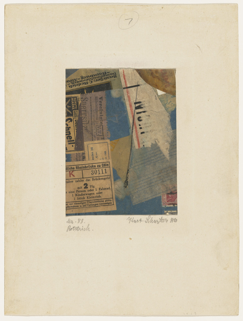
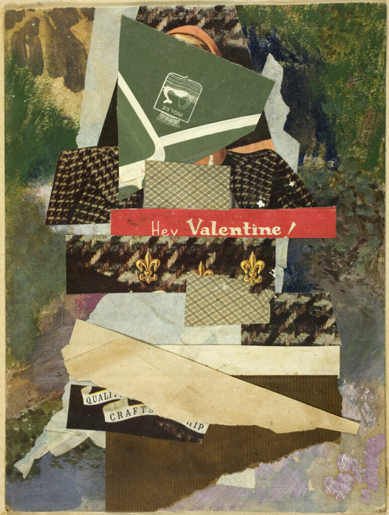
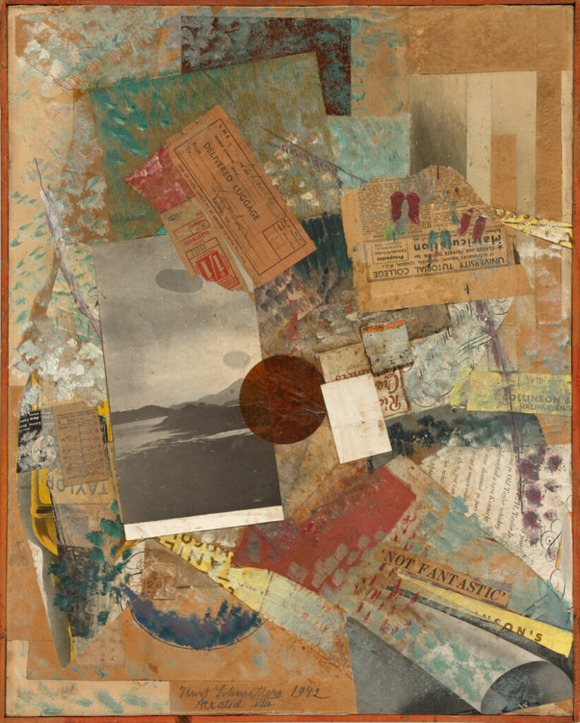
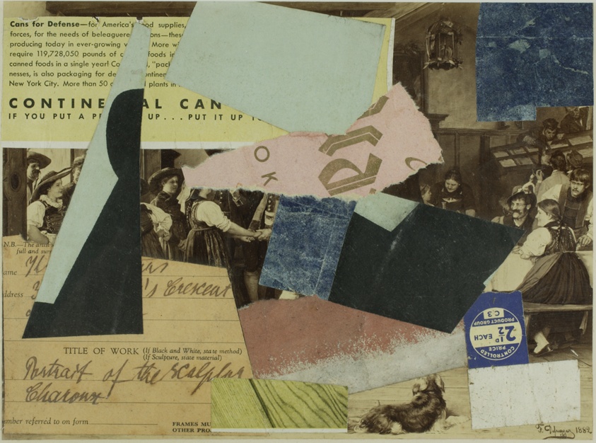
Kurt Schwitters collages are beautiful, could I do something similar with a screen buffer and digital fragments ?
***
ENSCI workshop :
-glitching workshop needs theoretical framework either of the practice of glitching or of the architecture of various files. Students felt they had no control, that the activity was meaningless and completely random. (Menkman Rosa 2010 A Vernacular of File Formats is the perfect thing for this)
-I need more moments where the students have to show what they are working on during the course of the workshop instead of just at the end or just informally.
-Somehow a dynamic formed wherein it was up to the workshop leader to make projects happen, and a certain number of the students, didn’t take the initiative to try and develop a mature (if very quickly made) project for the workshop.
-I did a better job than normal is revising and learning about the references and technical things I brought up in class before hand so I was more informed. I think I need to go even further to be really comfortable with what I’m talking about.
*************
This viewfinder prism thing is incredible, it somehow automatically focuses and it has the backlit quality that feels like it must be powered even though it’s not.
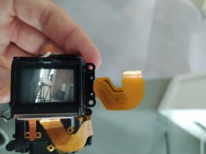
I fell in love with this thermal printer camera combo, could it be a workshop unto itself ? :
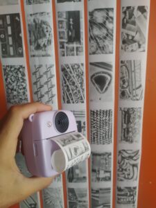
Trying to see if I could control the thermal printer mechanism myself ?
https://www.alibaba.com/product-detail/2-Inch-Original-Thermal-Receipt-Printer_1601425785504.html
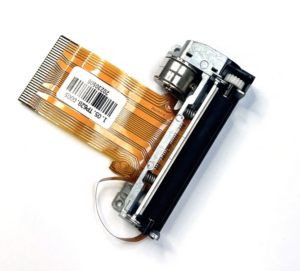
https://www.alibaba.com/product-detail/QJ486-101-2Inch-Thermal-Printer-Head_1601779477708.html?spm=a2700.prosearch.normal_offer.d_image.276567afnEGOJb&priceId=3b08110c5d97474b979cd0218d1ff567
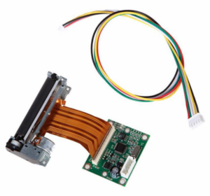
https://download.mikroe.com/documents/datasheets/LTP02-245-13_datasheet.pdf
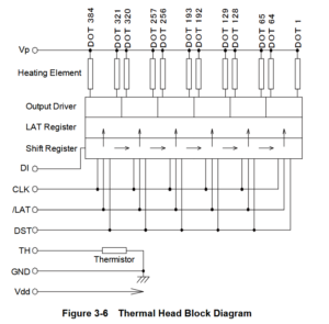
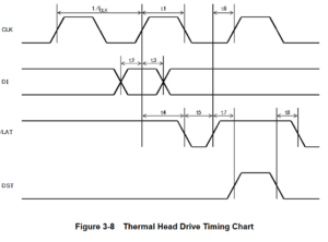
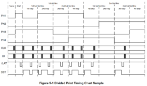
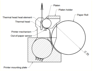
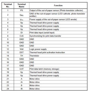
I can now put VGA output, HDMI output, rpi input, and camera input in the ACHIEVED category ! I can already to a VGA electronics workshop where the video input is from a camera and not from the rpi. Next versions could also select between an SD card raw video and camera input. This could work for NO SCHOOL next year for instance and obviate the need for rpis completely and make something inexpensive enough that the students could keep after (cost : OV7670, FPGA, SD card holder, SD card, VGA female). At the same time, I think I am actually getting tired of glitching, especially when I saw how cool it was to have low res pictures that I could print on the Chinese camera.
I am thinking of revisiting LCD, SD card, and making a board for a thermal printer and getting help from AI.
Basically, having a physical output from my machine just seems so much more valuable than endlessly manipulating images. Though a physical mini screen on the FPGA board would make things more tangible, it remains kind of virtual like a smart phone. The idea of physically printing something is appealing. Printing out glitched things doesn’t really work with the low resolution of the printer unfortunately. So I think the printing camera really has to be an actual normally functioning device. The interest in using it over buying a Chinese printing camera would be the custom design, the learning I would gain for doing the project ? It certainly won’t ever be cheaper than the Chinese cameras so I have to subtract this from my stated motivations.
I am also getting a bit tired of glitching and distorting digital images and video…
It connects with a project like Tom Garçon’s low resolution projector. Essentially let’s not store big files when little ones do fine for many things. It goes a step further into not even storing files on an SD card but just printing them right away. As a designer to have quick records of things and be able to collage them all together could actually be useful. It also takes keeps taking me in the direction of machine vision, but away from screen into something physical.
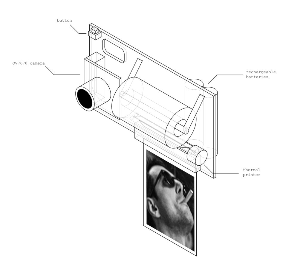
Have a more detailed picture of the thing now. As usual I am first excited about making some low cost kit for a workshop / open source product, then I realize that the best thing for a workshop is not a custom board but existing tech (like a rpi in DPI mode for the video workshop). Then I remember the prepared instrument obsession and start adding DIP switches everywhere to modify the parameters of the device and it becomes more of an expensive, one-off idiosyncratic artist tool.
Can a camera work without a viewfinder ? What about a screen ? Now I’m questioning the interest of making the thermal printer controller from scratch. I think it will take a while.
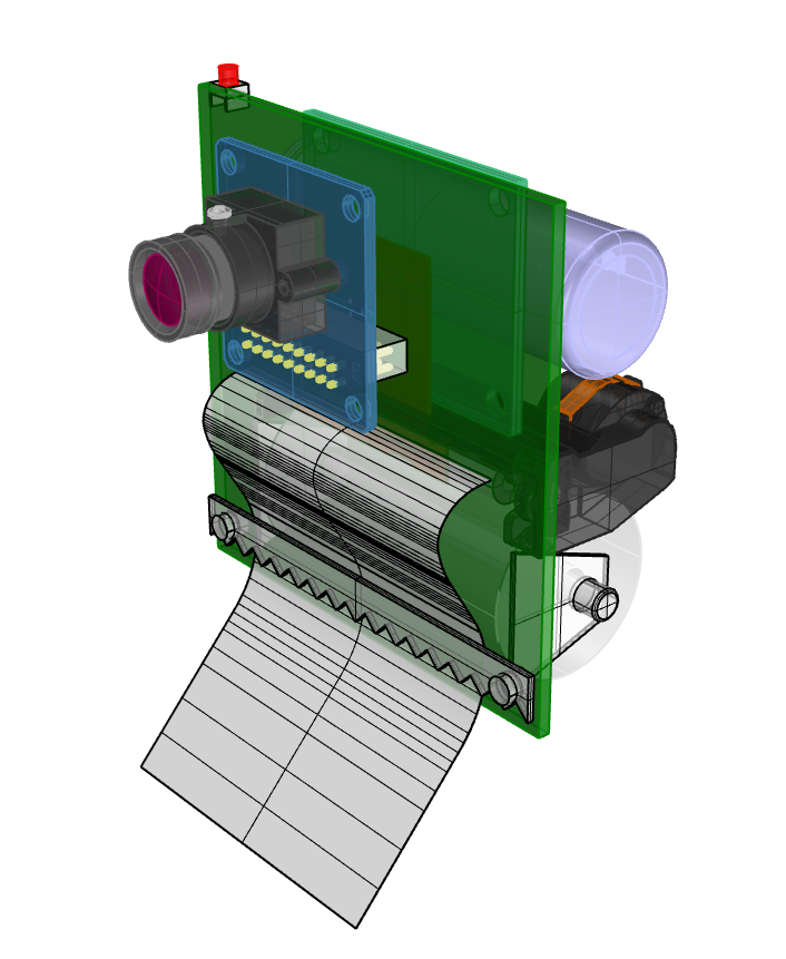
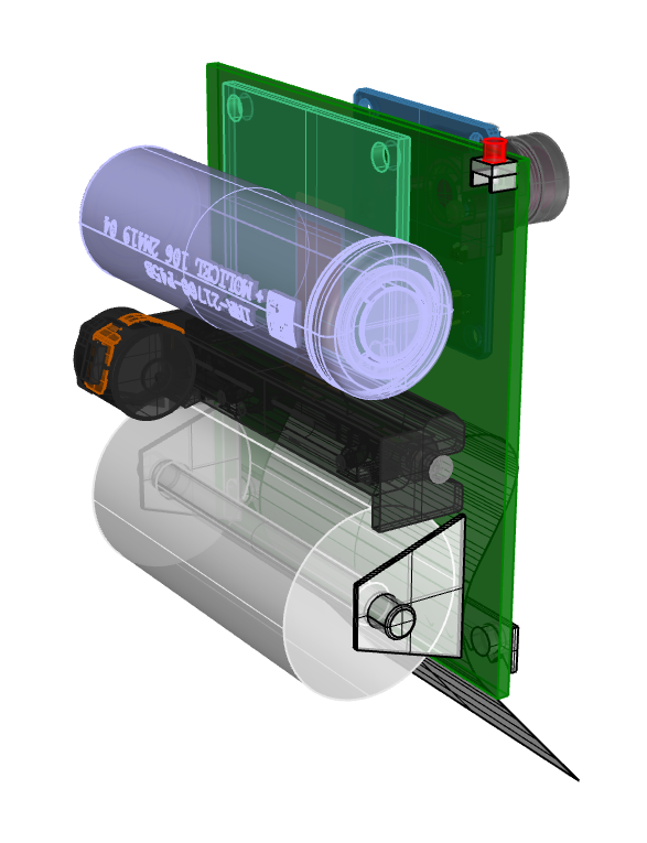
Blurg, need serious battery power to make the printing part work. It also drains battery fast. I am having second thoughts, maybe I should just focus on the portable camera + screen + SD card aspects for now and include a 5 pin header so I can test the printer still.
M12 lens attachments that fit on the OV7670 :
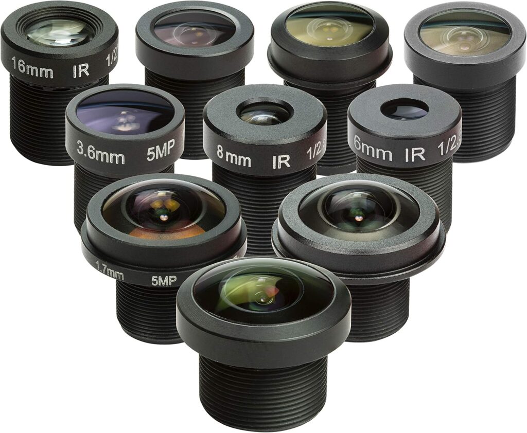
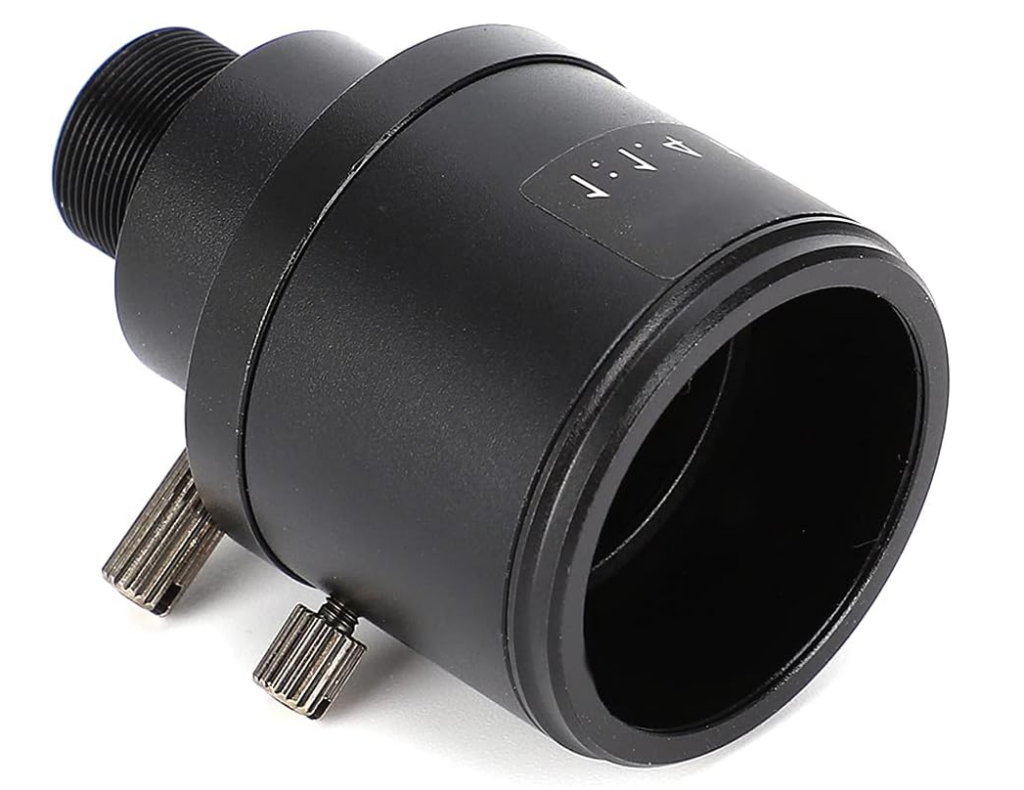
Zoom lens would be cool also though it would crop the image ?
Also ESP32-CAM module is an important reference. I’m doing the ghetto version of what it can do. AI suggests using the camera to document the very same workshop where the camera is assembled, meta !
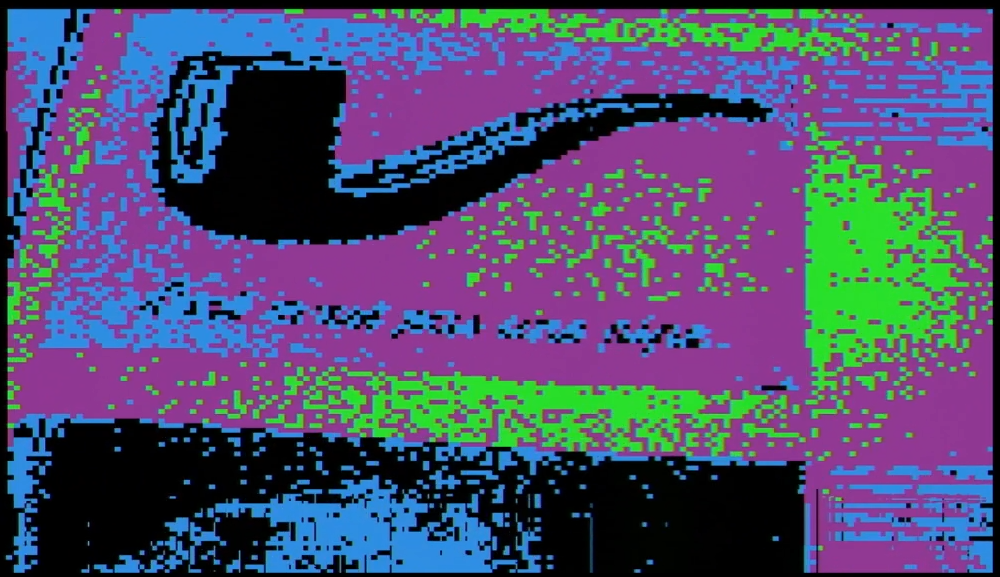
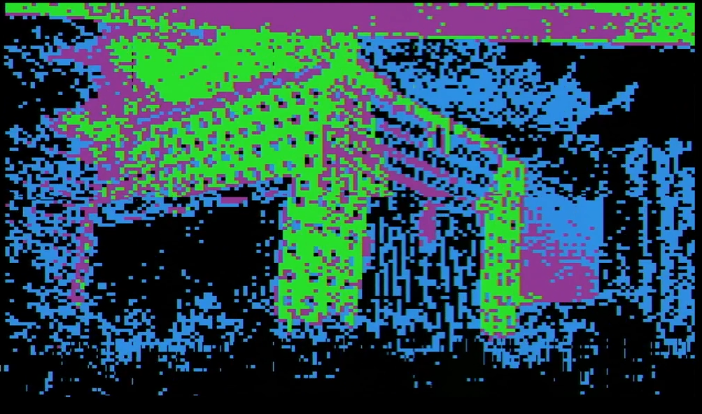
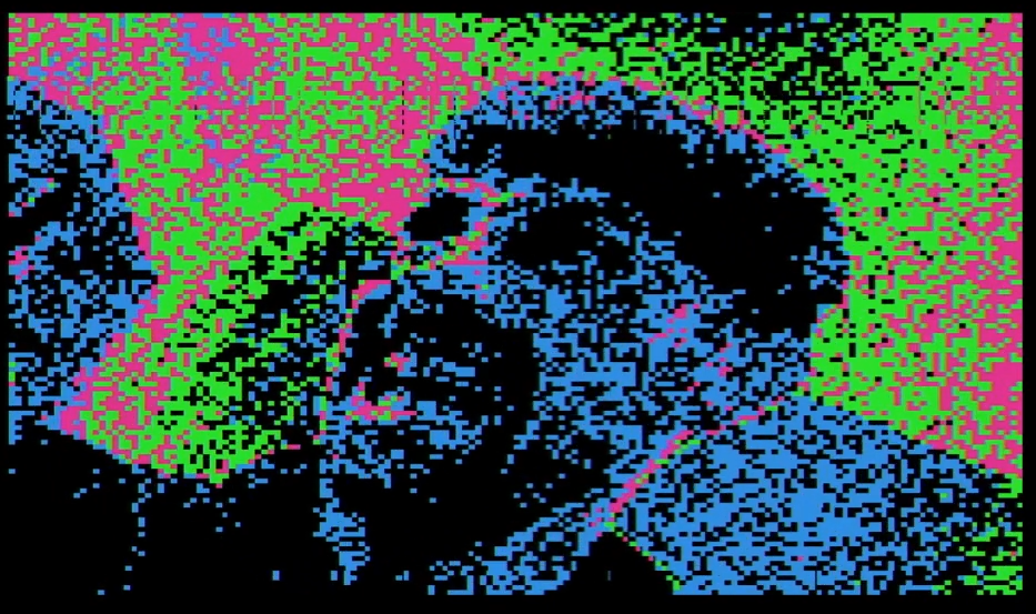
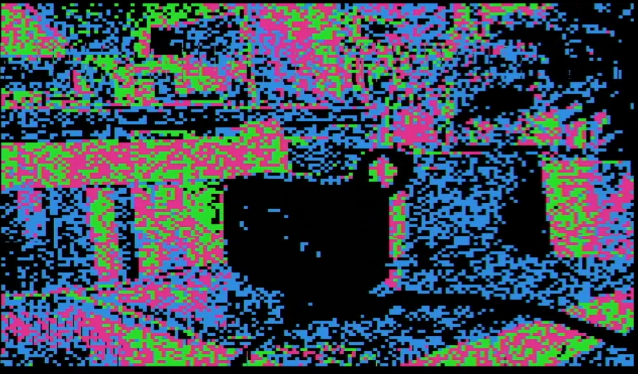
Going full prepared camera (dip switches control registers in the OV7670, and at the bottom a 3×3 binary convolution kernel :
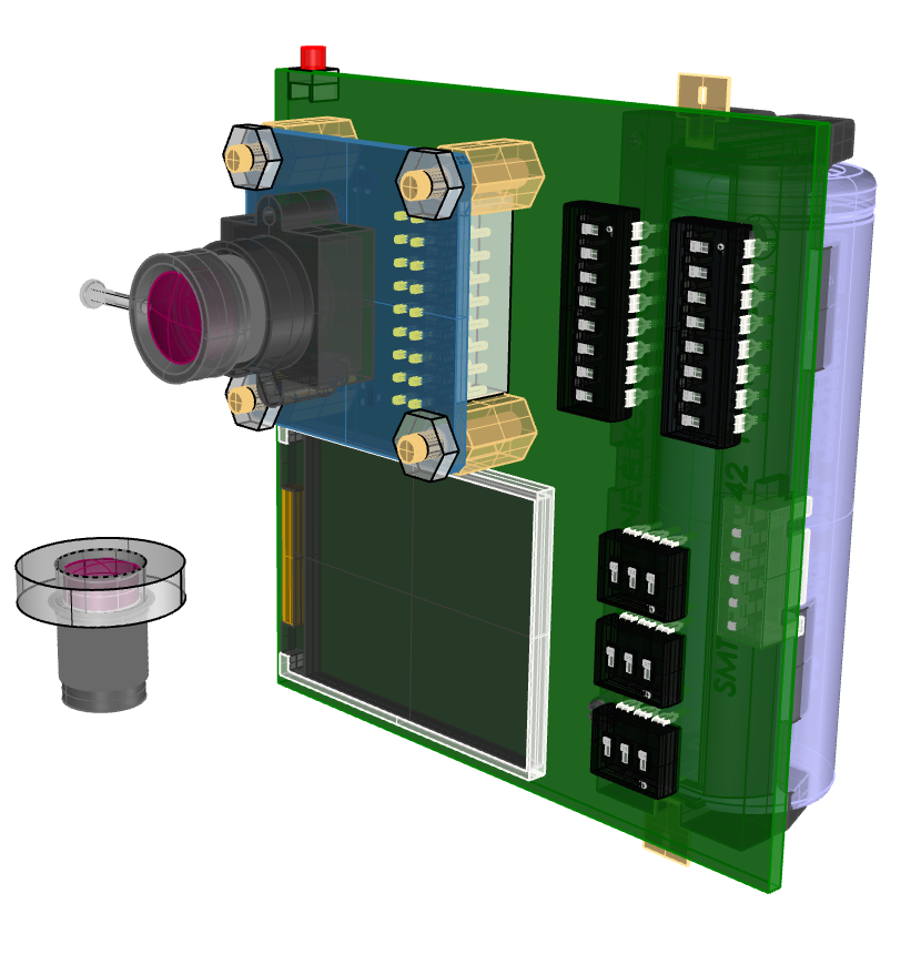
OK, now I’m reminded that I have the opportunity to build a custom board and make order anywhere I want for the workshop taking place at the Maison de l’Humanité in November. It’s a great opportunity to make a board that other people will get to keep. It could serve as the backbone for the workshop as it could generate VGA, for the hardware VGA experiments, could store RAW images, for the part on glitching and image file formats, and it could be circuit-bent, by adding jumpers between the camera and the board. It could be actually low cost without the printer and actually usable afterwards by the participants.
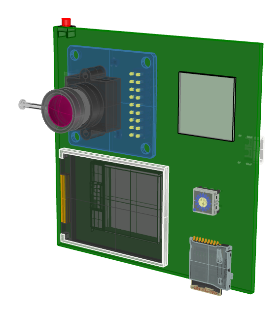
Additional features :
- focus adjustable camera, they can also play with different lenses from a M12 lens kit we’ll supply for testing
- no atmega this time as I discovered the OV7670 turns on with default params no problem.
- Binary encoded rotary switch to change 16 different register values in the camera but without expensive DIP switches
- rechargeable lithium ion battery (300-400mAh?) with USB C makes the device portable
- A 5 pin out to test with the thermal printer module I bought.
- VGA RGB V H pins broken out
Next steps :
- Design new board and get parts list + cost for Maison de l’humanité workshop meeting.
- Find TFT screen I already designed and get it working.
- Practice with SD card board I have storing raw data onto the SD card.
****
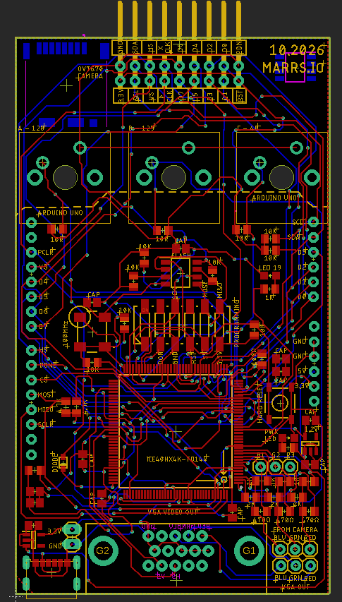
I have made a new version of the OV7670 camera board for the Maison de l’humanité workshop next month.
- It has the HX4K in place of the HX1K which is out of stock globally. This will help do convolution with 80K of BRAM instead of 64K.
- I found an automotive version of the Micron flash chip that is now obsolete.
- It now doesn’t require the Arduino to power up.
- Fixed the spacing on the buttons and the space between the camera and the buttons.
- Added pinouts for 3 bits of the VGA out colour and made it now 3 bits per color.
- I added footprints for an SD card and an SPI external SRAM in case I want to try to hack these onto the board later.
****
ERRATA :
- I put a big circle around the clock output of the oscillator and then mistook it for the PIN 1 marker which is actually diagonally across. This caused the LDO to overheat.
- I forgot to put a ground pour in the final version of my board so the board house appears to have done it for me and made it extra tight. This is resulting in a massive thermal mass which is making soldering hard.
- I forgot to ask for a stencil, it would have been so much easier to put these board in the oven.
- the USB plug is a little snug against the VGA board.
- Remember to update the flash chip in ICE Programmer to the automotive version, it’s the N25Q032A now.
- I think I should have an atmega handle the SD card which seems like a nightmare to do with an FPGA without hacks.
****
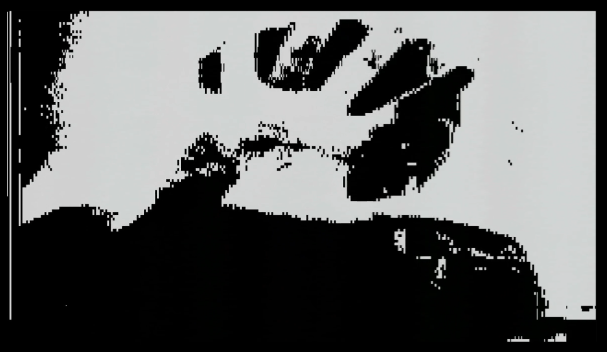
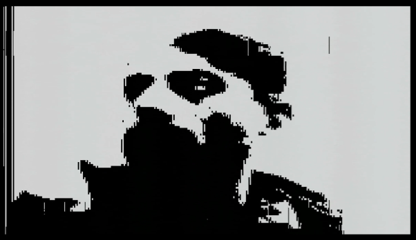
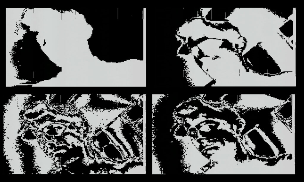
Some nice double pixel packing images :
diff input bit code :
and some different filters :
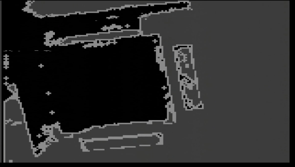
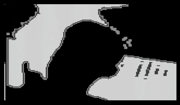
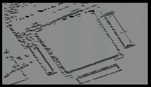
Could try to do keying (green screen), identifying simple shapes and drawing a bounding box around them, diff colours for different kinds of forms.
****
I have finally got the I2C communication kind of working with the camera. Claude helped me correct stuff I wouldn’t have caught honestly.
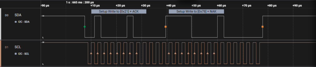
it’s decoded wrong, not sure why. There was a soldering issue related to a delaminated via I think which was causing the issues where Arduino was trying to send commands.
Here are some that are noticeable even with the downsampling (decimating?) and only two bits :
wrReg(0x1B,0x30); // shearing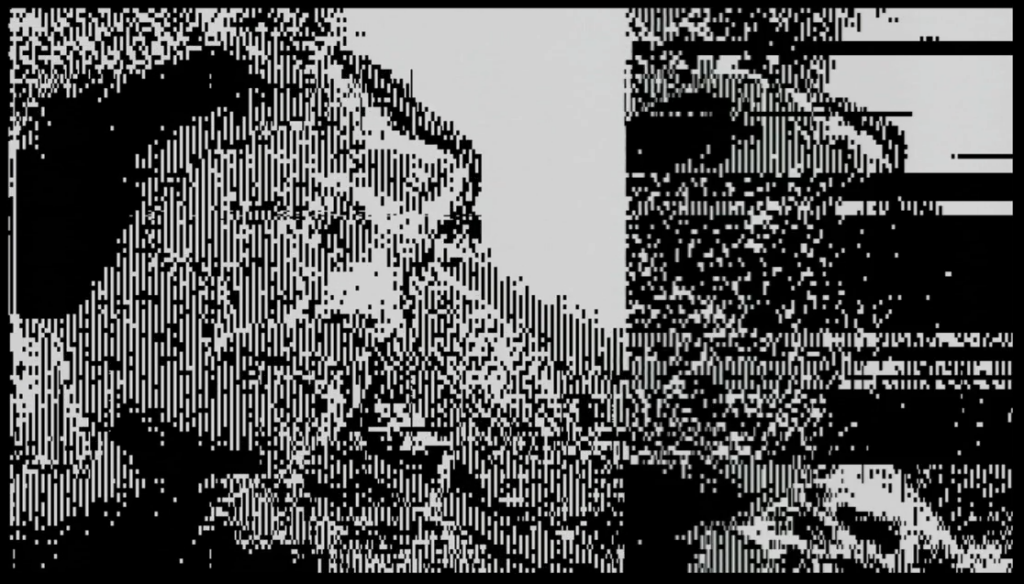 wrReg(0x17, 0x30); // cut the image in half
wrReg(0x18, 0x61);
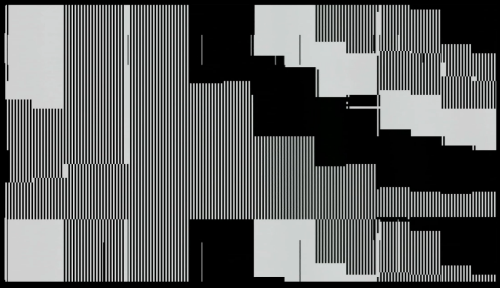
 wrReg(0x70, 0xBA); // colour bars
  wrReg(0x71, 0xB5);
wrReg(0x3D, 0x80); // gamma magic wrReg(0x7A, 0x05); wrReg(0x7A, 0x40); wrReg(0x7B, 0x50); wrReg(0x7C, 0x62); wrReg(0x7D, 0x75); wrReg(0x7E, 0x8A); wrReg(0x7F, 0x95); wrReg(0x80, 0xA0); wrReg(0x81, 0xAA); wrReg(0x82, 0xB2); wrReg(0x83, 0xBA); wrReg(0x84, 0xC2); wrReg(0x85, 0xCC); wrReg(0x86, 0xD4); wrReg(0x87, 0xE2); wrReg(0x88, 0xEE); wrReg(0x89, 0xF8);
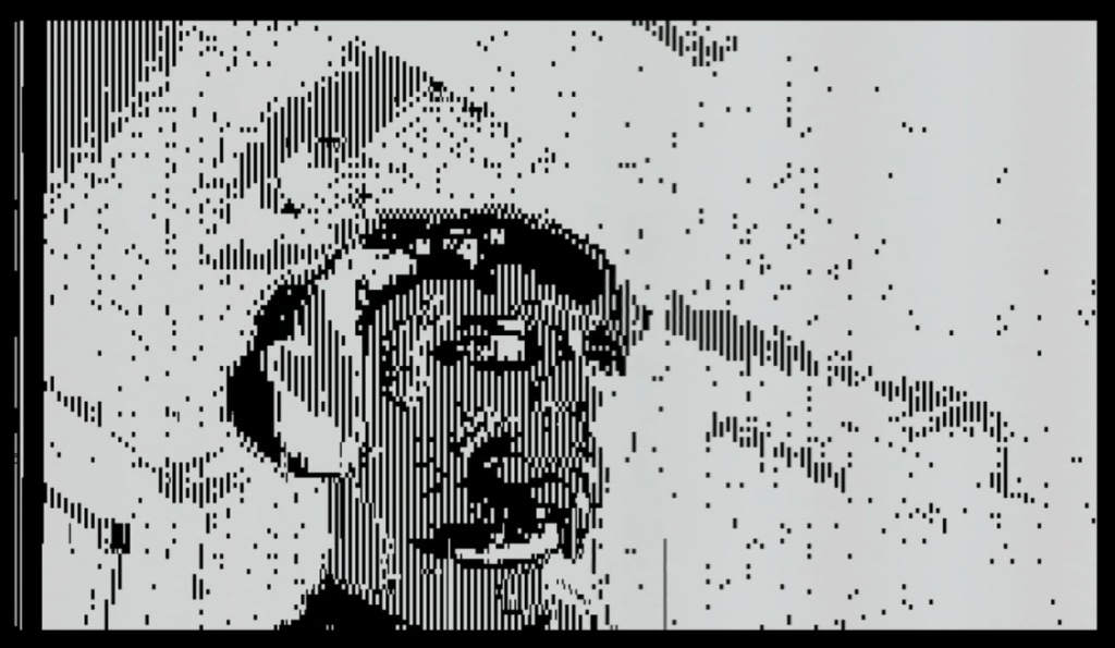 wrReg(0x2D, 0xB0);//madness
wrReg(0x2E, 0xB0);
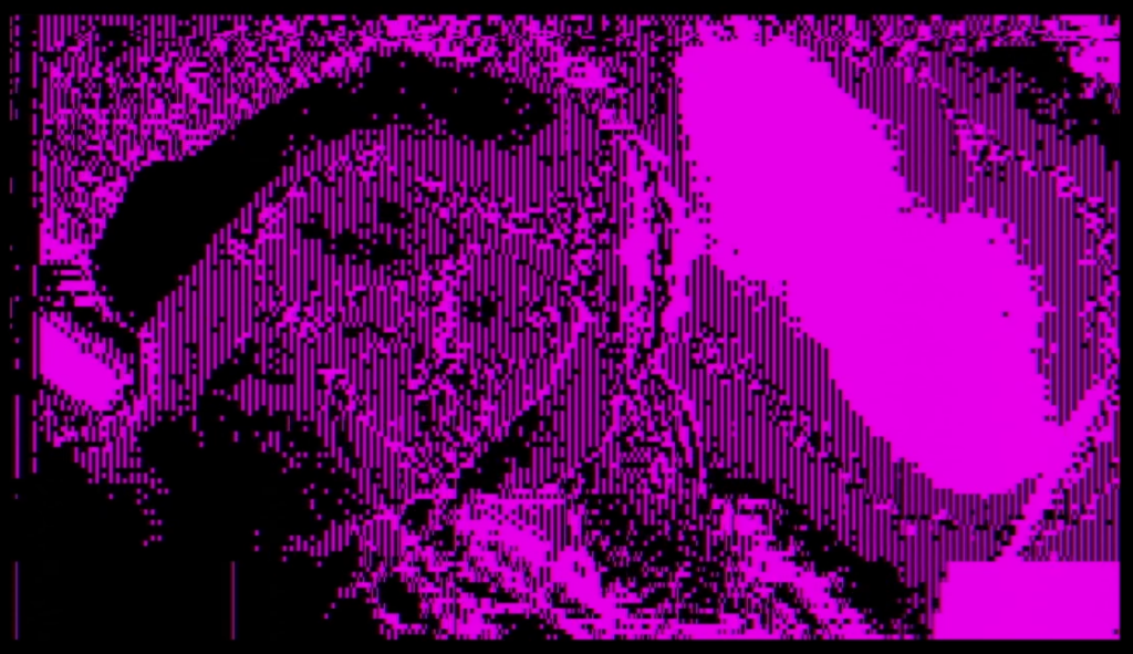
Removing the jumpers that go between the 3 colours and the VGA out when in black and white mode allows you to select your output color !
****
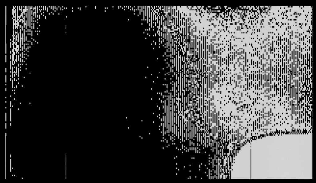
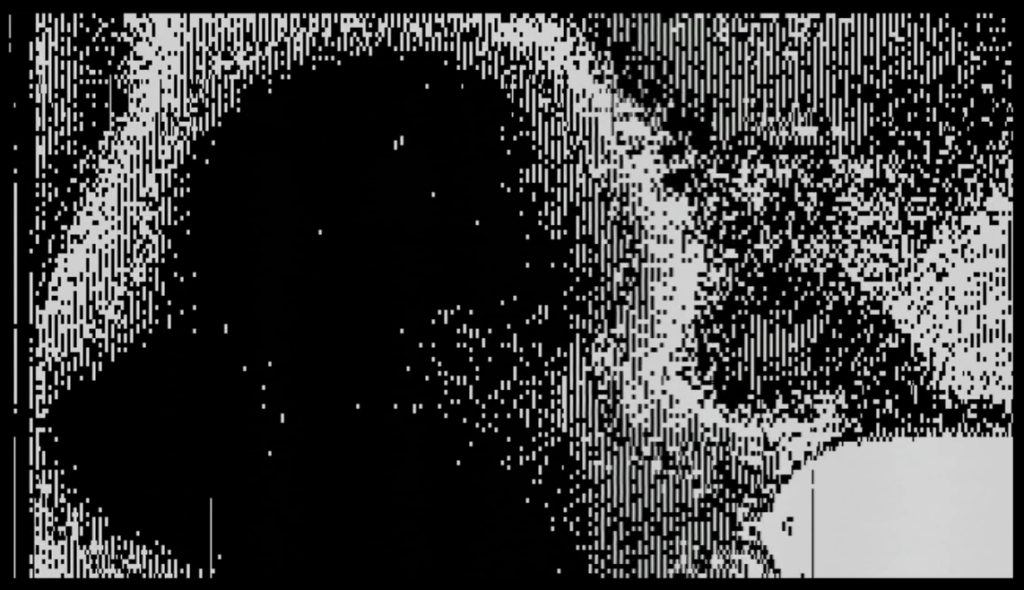
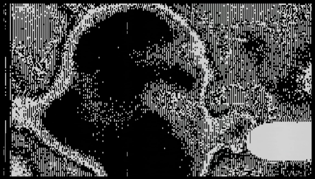
Tested changing the focus :
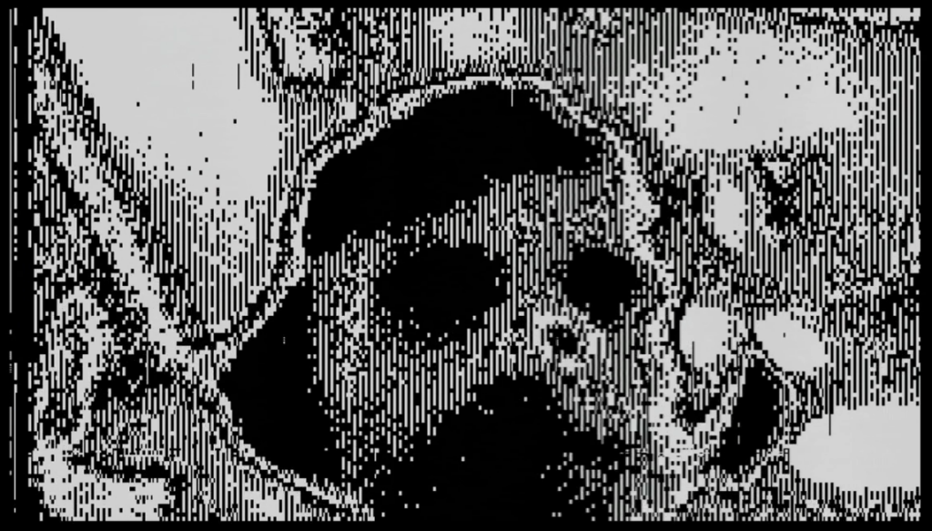
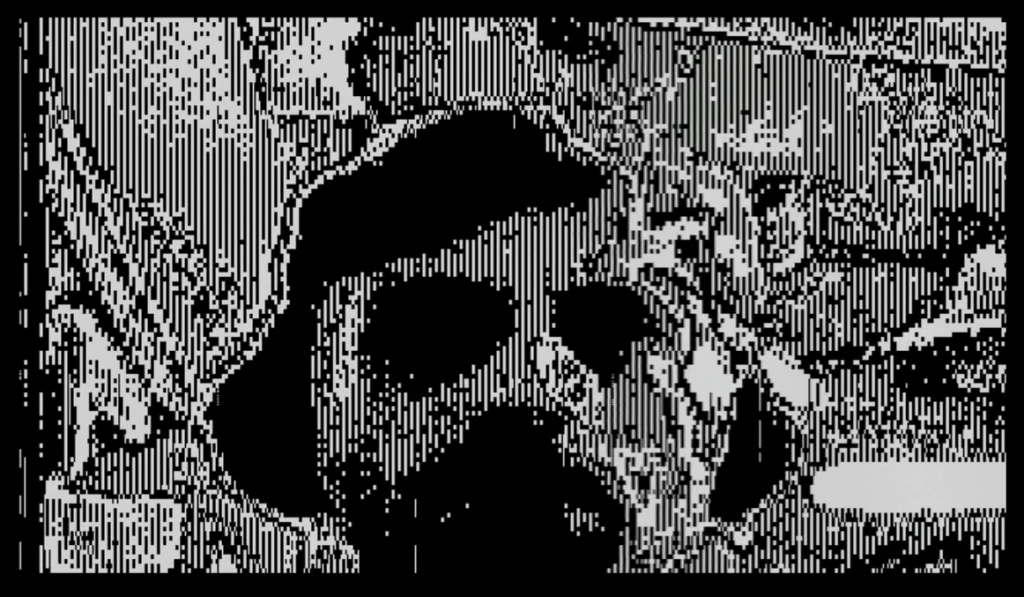
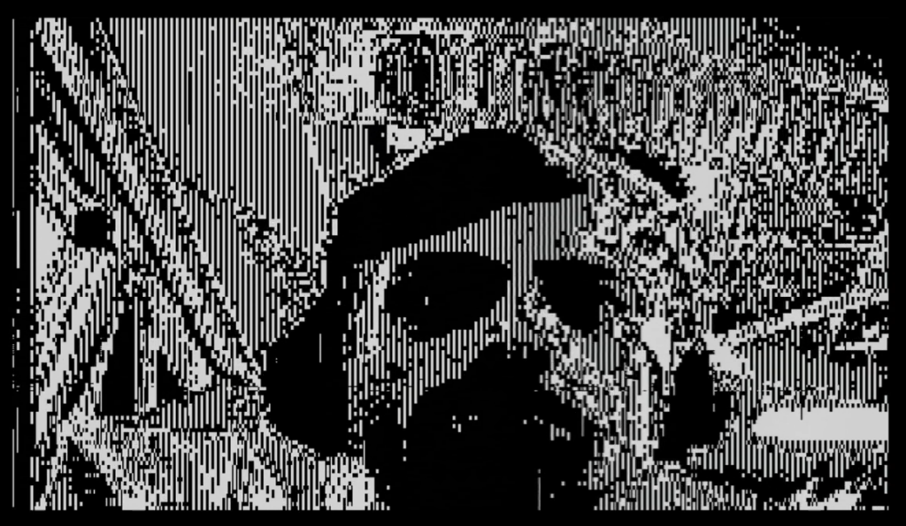
Also looked in to the open source toolchain, it’s very simple.
Downloaded and unzipped from the release page : https://github.com/YosysHQ/oss-cad-suite-build/releases/tag/2026-10-28
yosys synthesizes verilog into a .json, nextpnr takes the .json and constraints and does placing and routing to produce an .asc file, icepack creates the binary image from the .asc. Everything is done in the terminal.
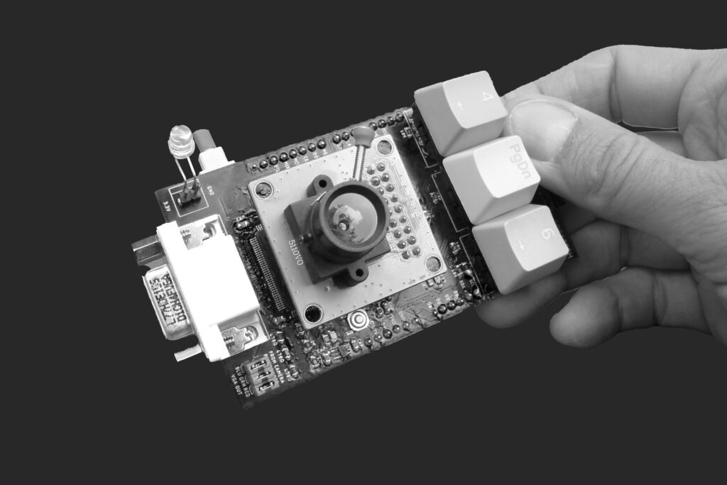
Also made a new image from the camera prototype :
****
Here is a possible BRAM arrangement to have a 320×240 1bpp screen buffer made from 20 16×256 blocks in the HX4K :
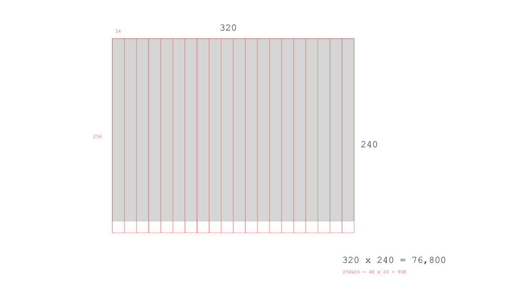
To instantiate it I’ve replaced the default ram.v file I’ve been using with this modification :
reg [data_width-1:0] mem [5119];****
EDIT : I’ve given up trying to source a TFT screen and incorporate it into an FPGA board for the moment. I’ve pivoted back to Convolution and the machine vision dimension which feels conceptually richer and less ecologically questionable than making a portable toy.
Convolution is difficult with the current board using only BRAM. The easiest is to have plenty of space for 3×640 registers to store pixels so that the binary convolution can be done combinatorially with a single assign. However space is tight on the HX1K. The other option is using the memory space between 20k and 32k beyond the 160×120 image area. However this is tough because the dual port BRAM is set up so that the OV7670 camera pixel clock controls the writing and the faster FPGA clock controls the reading. This means hacking together a situation where the camera writes 640×3 lines to the non-visible memory space while waiting to write the first of the 160×120 to BRAM, then the FPGA reads this 640×3 and calculates the convolution and puts the 160 convoluted pixels into a register for the VGA color generator to output when the time comes.
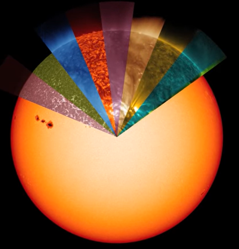
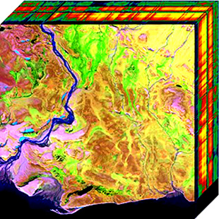
Hyperspectral imaging where you can capture a continuous range of different frequencies instead of bands :
***********
Here’s my convolution code :
reg [3:0]sequencer = 0;
reg [8:0] kernel = 9'b111111111;
//reg [8:0] kernel_mask = 9'b010101010;
//blur = 9'b111
// 111
// 111;
//edges = 9'b111
// xxx
// 000;
//edges = 9'bx0x
// 010
// x0x;
reg [3:0] total;
reg a,b,c,d,e,f,g,h,i;
reg [1:0]current_pixel;
reg [1:0]next_pixel;

////COLOR GENERATION
always @(posedge clk) begin
if (display_en) begin

if (((h_counter>>2) < 159) && ((h_counter>>2) > 0) && ((v_counter>>2) < 119) && ((v_counter>>2) > 0 )) begin

sequencer <= sequencer + 1; // increment
//read nine neighbour pixels and convolve
case (sequencer)
4'b0000: begin
current_pixel <= next_pixel;
read_address <= ((h_counter>>2)-1) + (((v_counter>>2)-1)*160);
//wait two cycles for the valid data to appear
end
4'b0001: begin
read_address <= ((h_counter>>2)) + (((v_counter>>2)-1)*160);

end
4'b0010: begin
read_address <= ((h_counter>>2)+1) + (((v_counter>>2)-1)*160);
a <= ~(kernel[0]^ram_data_out);

end
4'b0011: begin
read_address <= ((h_counter>>2)-1) + ((v_counter>>2)*160);
b <= ~(kernel[1]^ram_data_out);

end
4'b0100: begin
read_address <= (h_counter>>2) + ((v_counter>>2)*160);
c <= ~(kernel[2]^ram_data_out);

end
4'b0101: begin
read_address <= ((h_counter>>2)+1) + ((v_counter>>2)*160);
d <= ~(kernel[3]^ram_data_out);

end
4'b0110: begin
read_address <= ((h_counter>>2)-1) + (((v_counter>>2)+1)*160);
e <= ~(kernel[4]^ram_data_out);

end
4'b0111: begin
read_address <= ((h_counter>>2)) + (((v_counter>>2)+1)*160);
f <= ~(kernel[5]^ram_data_out);

end
4'b1000: begin
read_address <= ((h_counter>>2)+1) + (((v_counter>>2)+1)*160);
g <= ~(kernel[6]^ram_data_out);

end
4'b1001: begin h <= ~(kernel[7]^ram_data_out);

end
4'b1010: begin
i <= ~(kernel[8]^ram_data_out);

end
4'b1100: begin
total <= {3'b000, a} +{3'b000, b}+{3'b000, c}+{3'b000, d}+{3'b000, e}+
{3'b000, f}+{3'b000, g}+{3'b000, h}+{3'b000, i};

end

endcase

if (total >= 1 && total <= 3) begin
next_pixel <= 2'b01;
end
else if (total >= 4 && total <= 6) begin
next_pixel <= 2'b10;
end
else if (total >= 7 && total <= 9) begin
next_pixel <= 2'b11;
end
else begin
next_pixel <= 2'b00;
end

if (current_pixel==2'b01) begin

r_out <= 2'b01;
g_out <= 2'b01;
b_out <= 2'b01;
end
else if (current_pixel==2'b10) begin

r_out <= 2'b10;
g_out <= 2'b10;
b_out <= 2'b10;
end
else if (current_pixel==2'b11) begin

r_out <= 2'b11;
g_out <= 2'b11;
b_out <= 2'b11;
end
else begin

r_out <= 2'b00;
g_out <= 2'b00;
b_out <= 2'b00;
end
end
else begin
sequencer <= 0; // reset
r_out <= 2'b00;
g_out <= 2'b00;
b_out <= 2'b00;
end
end
else begin
r_out <= 2'b00;
g_out <= 2'b00;
b_out <= 2'b00;
end
end
///
*******
The world has apparently run out of HX1K FPGAs in the TQ144 package so I must update the board with the VQ100 package (but it is cheaper and I didn’t need the pins). The FLASH chip is now obsolete also so I need to find a new one that IceCube2 and Diamond Programmer support.
*******
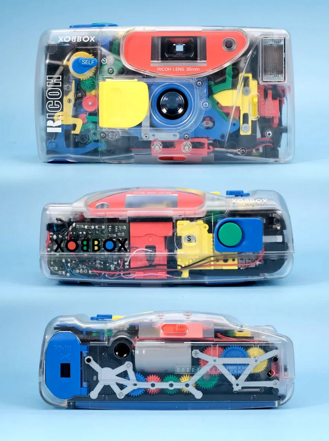
Check out this pretty camera :
I like this idea of going back to old fashioned physical media after five years working with pixels in memory and on screens. I did vector plotting, vector and raster screen photography, 3D printing of meshes, why not go back to paper and printing from this machine vision angle (with either scanning or photographing as the image input) and raster printing (either thermal printing, ink jet, etc.) ?
****
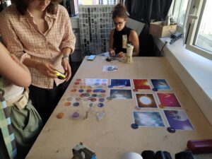
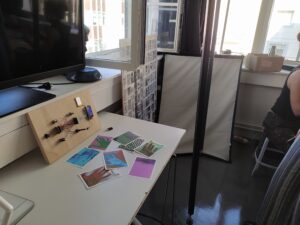
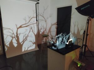
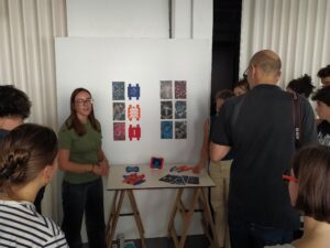
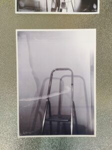
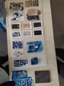
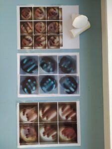
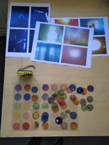
ENSCI Student work from the workshop:



*************
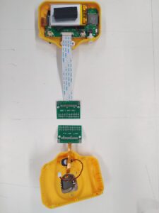
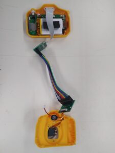
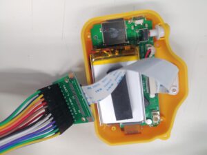
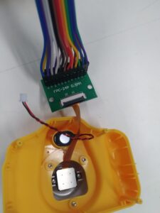
Here are the steps taking apart the camera and breaking out the 24 pins coming from the sensor :
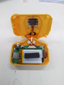
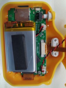
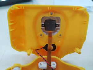
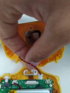
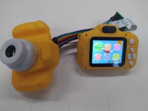
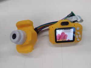
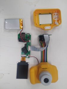
Here’s my first actual glitch
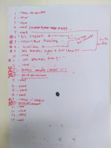
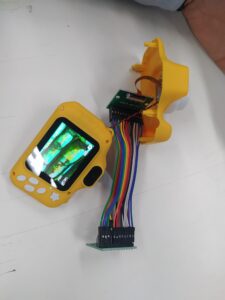
I discovered during the ENSCI workshop that I can use potentiometers between the camera and the motherboard.
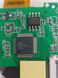
Here’s the one chip that appears to do everything, can’t find any info online though :
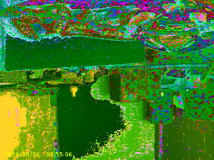
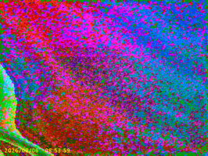
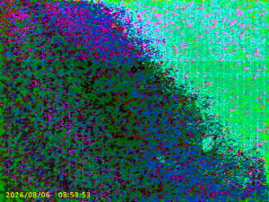
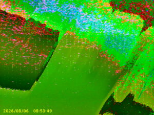
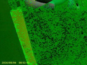
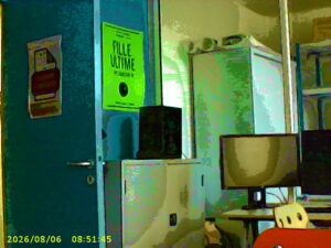
Here are some of the glitched results :
And here’s a site to get early 2000s Nikons in the D100, D70 etc series which were early digital cameras :
https://www.mpb.com/fr-fr/produit/nikon-d70
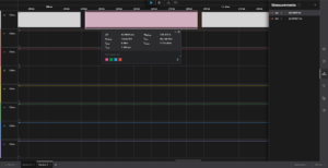
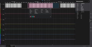
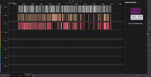
Looking at some of the camera pins on the logic analyzer :
***
Here are some tutorials :
https://www.youtube.com/watch?v=iJslS16d5Ug
https://ade3.substack.com/p/how-to-make-a-glitch-camera
- Caméra pour enfants
- FFC FPC Plat Câble, 24 Pin 0,5mm Pas :
- Convertisseurs FPC 24 broches 0,5 mm sur le côté de la prise arrière 1,0 mm vers DIP 2,54 mm
*****
AI has suggestions for hacking a webcam include undervolting and momentary button with resistor between D+ and D- lines.
AI gave some great artist recommendations :