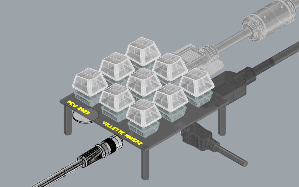
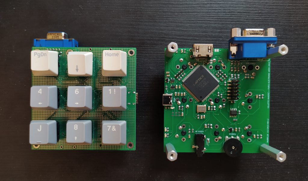
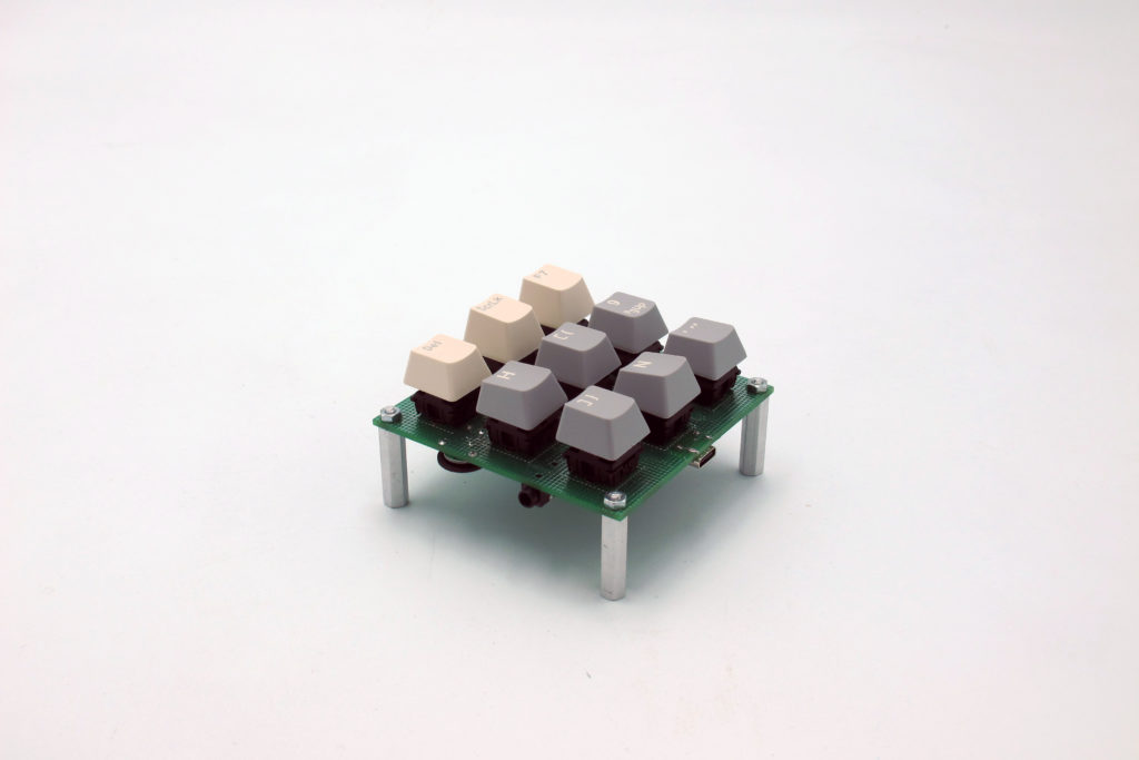
Making a simple FPGA video synth for PEW 2023 at Villette Makerz. It takes audio in and generates patterns based on the voltage threshold and the 9 keys being pressed.
The code is here : https://github.com/merlinmarrs/iCE40HX-verilog-video-patterns
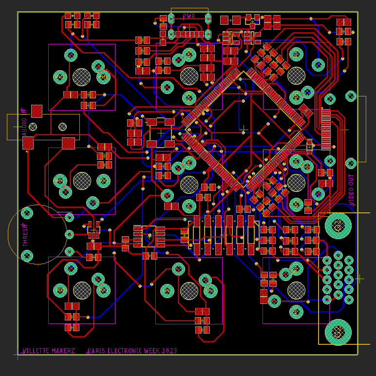
This time the top interface side has only buttons and no electronics. I have a simplified VGA out and HDMI with the correct LVDS resistor setup this time. I am relying on raspberry pi or arduino for programming.
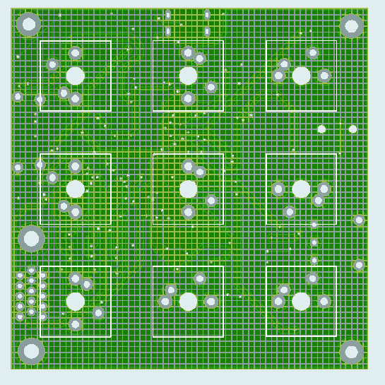
Trying a grid ground pour on the Stop layer :
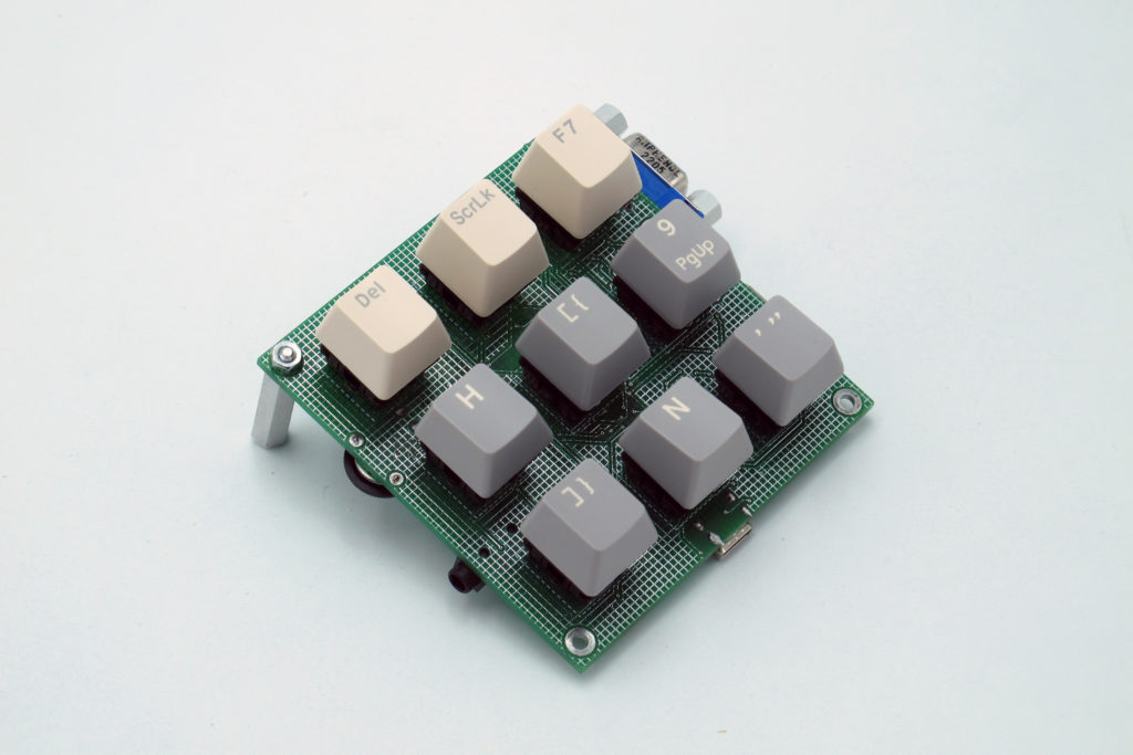
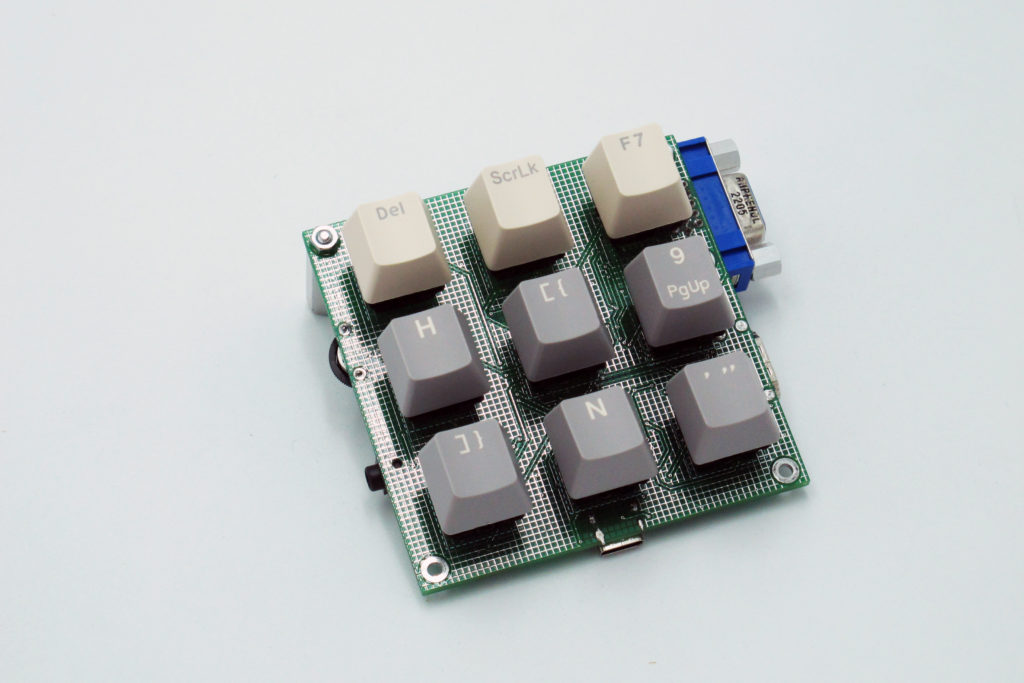
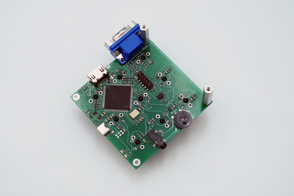
Here’s the final soldered version :
Nicer photos :
Found a site called OpenCores (https://opencores.org) that has free FPGA IP like math libraries.
Here are some tests with cool looking patterns :
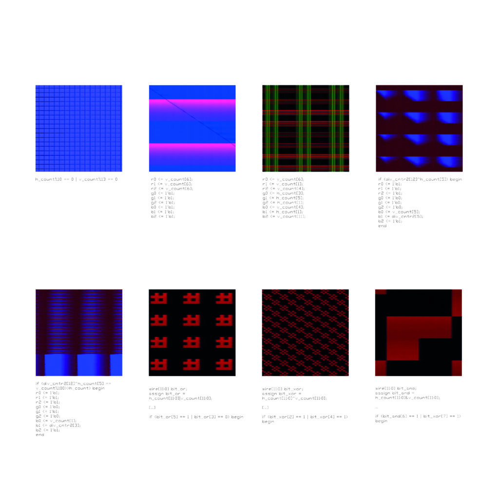
Because dividing, trig functions, etc. aren’t supported by default, the most promising is the bitwise boolean logic operating on the entire vector :
wire[11:0] bit_or;
assign bit_or = h_count[11:0] | v_count[11:0];

[...]

if (bit_or[5] == 1 | bit_or[3] == 0) begin
wire[11:0] bit_xor;
assign bit_xor = h_count[11:0]^v_count[11:0];
[...]
if (bit_xor[2] == 1 | bit_xor[4] == 1) beginwire[11:0] bit_and;
assign bit_and = h_count[11:0]&v_count[11:0];
...
if (bit_and[6] == 1 | bit_xor[7] == 1) beginI could imagine having the keys vary which logic operations are in play and having the music threshold change the color of the pixels for instance.
***
This site has a module for a quasi random number generator : https://simplefpga.blogspot.com/2013/02/random-number-generator-in-verilog-fpga.html
This site has some good Processing examples : http://www.generative-gestaltung.de/2/
***
If I do this workshop again I’d like to design it to be made on aluminum as, it is at least in principle, recyclable.
PCBWay’s diagram of a double layer board (https://www.pcbway.fr/pcb_prototype/General_introduction_of_Aluminum_PCB.html) :

***
Simplest imaginable keypad switch (and audio in post comparator) test works :
module top (
input hwclk,
output led1,
input keypad_c1
);

assign led1=keypad_c1;

endmodule`default_nettype none
module LFSR (
input clock,
input reset,
output [12:0] rnd
);
wire feedback;
reg [12:0] random, random_done;
reg [3:0] count; //to keep track of the shifts
assign feedback = random[12] ^ random[3] ^ random[2] ^ random[0];
assign rnd = random_done;
always @ (posedge clock)
begin
if (reset)
begin
random <= 13'hF; //An LFSR cannot have an all 0 state, thus reset to FF
count <= 0;
end
else
begin
if (count == 13)
begin
count <= 0;
random_done <= random; //assign the random number to output after 13 shifts
end
else
begin
random <= {random[11:0], feedback}; //shift left the xor'd every posedge clock
count <= count + 1;
end
end
end
endmodule
I am using it in the top code like this :
wire [12:0] random_number;

[...]

LFSR random_s(
.clock(clk_in),
.reset(reset),
.rnd(random_number)
);
***
Sine gen :
- https://miscircuitos.com/sinus-wave-generation-with-verilog-using-vivado-for-a-fpga/
- https://zipcpu.com/dsp/2017/07/11/simplest-sinewave-generator.html
- https://verilogcodes.blogspot.com/2015/11/verilog-code-for-simple-sine-wave.html
I added a time delay module I modified from the led_rotation example :
`default_nettype none
module tempo(
input wire clk,
output reg half_sec_pulse
);

reg[25:0] div_cntr1;
reg[25:0] div_cntr2;
always@(posedge clk)
begin
div_cntr1 <= div_cntr1 + 1;
if (div_cntr1 == 0)
if (div_cntr2 == 0)
begin
div_cntr2 <= 0;
half_sec_pulse <= ~half_sec_pulse;
end

else
div_cntr2 <= div_cntr2 + 1;
else
half_sec_pulse <= half_sec_pulse;
end

endmodule
I can’t figure out why this makes 1/2 second ish though. Google says it should last 130.312488 days…Perhaps the compiler is deciding it doesn’t have enough space to store it and it truncating it?
From the led_rotation code I get 2^16 = 65536, this happens 91 times so 65536x91, then multiplied by the period of a 12MHz clock (83.3ns) gets me to around 0.49 seconds.
I’m guessing it is getting clipped because the register is too big ?
*****
Fabien showed me that on AliExpress you can buy things like this tracking ball for cents :
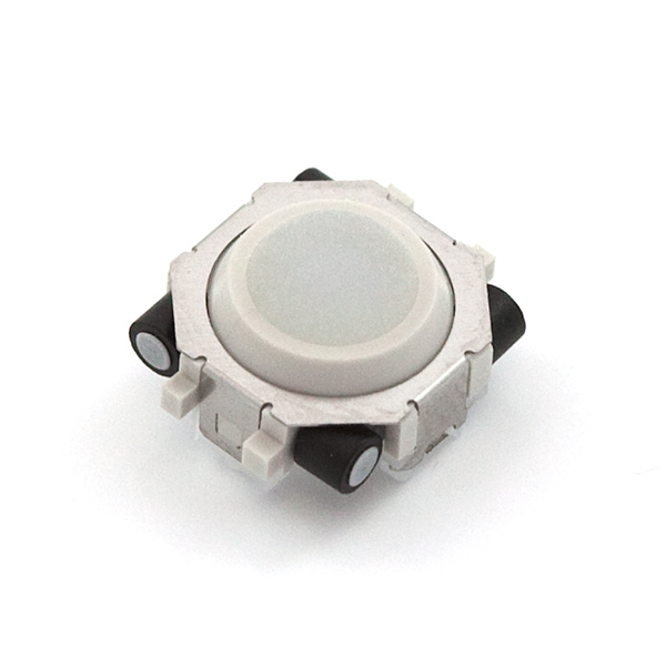
https://fr.aliexpress.com/item/1005004324983317.html?spm=a2g0o.detail.0.0.3f40hagUhagUgw&gps-id=pcDetailTopMoreOtherSeller&scm=1007.40000.327270.0&scm_id=1007.40000.327270.0&scm-url=1007.40000.327270.0&pvid=83e84367-84b9-424f-b42a-31b87563ff5e&_t=gps-id:pcDetailTopMoreOtherSeller,scm-url:1007.40000.327270.0,pvid:83e84367-84b9-424f-b42a-31b87563ff5e,tpp_buckets:668%232846%238114%231999&pdp_npi=4%40dis%21EUR%210.80%210.72%21%21%216.14%21%21%40211b801516946910696348428ea8cb%2112000030031307832%21rec%21FR%21%21ABS&search_p4p_id=202309140431096642081558243384177015_4
Each one requires four little hall effect sensors which output HI-LOW pulses. The one made by Sparkfun is the AN48841B : high sensitivity CMOS Hall IC Operates on Alternating Magnetic Field (low-speed rotation for lock detection). Trying to find an alternative for not too much on Mouser.
https://www.mouser.fr/ProductDetail/Infineon-Technologies/TLI49632MXTSA1?qs=0DP5yvOrqYlmAP5lA6MTRA%3D%3D
I am also thinking about an HDMI mini – not micro – (if I can get HDMI working, if not get a helper chip), an atmega2560 to handle the SD card communication. Possibly a USB charger and a battery too – so that there can really be a minimum of cables when the battery is charged up.
A dumb-proof programming connector with an automatically controlled bus to disconnect the programmer from the FPGA when reset not asserted so I don’t need to unplug and replug every time ?
*****
NEXT BOARD THOUGHTS :
Maybe I don’t need to rebuild the FPGA etc each time, but should just make interfaces that plug into it ?
The only thing left to try in hardware is the SD card fetching video data and then putting it on screen, and perhaps test having way more bits for each color and using the 4K LUT version of the iCE40.
I could also try using the specialized HDMI chip ? This would allow me to try the mini screen.
VGA with like 64 bit color !!!
put the remaining video ICs that I haven’t played with yet (video differentiator, video sync module, etc.) on the board !
Combine the possibility of reading a video from an SD card, having memory to store it in, and having a bunch of keys to press, AND coming up with code that makes meaningful patterns.
My leftover video ICs :
- ADV7125 8 bit Triple HS Video – https://www.mouser.fr/pdfdocs/ADI_ADV7125_Datasheet.PDF
- LT1251CN Video Fader – https://www.mouser.fr/datasheet/2/609/12516fa-3123106.pdf
- 660GILFT Digital Video Clock – https://www.mouser.fr/datasheet/2/698/REN_660_DST_20100514-1995937.pdf
- NJM2274R Low Power CI video w/ Y-C mixer – https://www.mouser.com/datasheet/2/294/NJM2274_E-1917180.pdf
- FMS6143CSX Video Filter Driver – https://www.mouser.fr/datasheet/2/308/1/FMS6143_D-2313627.pdf
- AD724JRZ – https://www.mouser.fr/datasheet/2/609/AD724-3118543.pdf
*****
PATTERN CODE THAT WORKS :
Got a code that works :
`default_nettype none

module vga_sync_test(

input wire clk_in,
input wire reset,
input wire key[8:0],
input wire adc_in,
output reg led_red,
output reg led_green,

//VGA OUT

output reg [3:0] r_out,
output reg [3:0] b_out,
output reg [3:0] g_out,
output wire h_sync,
output wire v_sync

);

wire half_sec;
wire [12:0] random_number_0;
wire [12:0] random_number_1;
wire [12:0] random_number_2;
wire [12:0] random_number_3;
wire [12:0] random_number_4;
wire [12:0] random_number_5;
wire [12:0] random_number_6;
wire [12:0] random_number_7;
wire [12:0] random_number_8;
wire [12:0] random_number_9;
wire [7:0] sine_wave;
wire display_en;
wire [11:0] h_count;
wire [11:0] v_count;

localparam h_pixel_max = 1280;
localparam v_pixel_max = 960;
localparam h_pixel_half = 640;
localparam v_pixel_half = 480;
localparam h_pixel_25 = 320;
localparam v_pixel_25 = 240;
localparam h_pixel_75 = 960;
localparam v_pixel_75 = 700;

//VGA COLOR OUT

always @(posedge clk_in) begin

if (display_en) begin

if ( key[0] == 0 &&

h_count < h_pixel_25 + random_number_1[4:0] && v_count < v_pixel_25 + random_number_7[8:5] &&
h_count > h_pixel_25 - random_number_2[4:0] && v_count > v_pixel_25 - random_number_2[8:5]

) begin

r_out <= random_number_1[3:0];
g_out <= random_number_5[3:0];
b_out <= random_number_9[6:4];

led_green <= 1;

end

else if ( key[1] == 0 &&

h_count < h_pixel_half + random_number_7[5:0] && v_count < v_pixel_half + random_number_7[10:5] &&
h_count > h_pixel_25 - random_number_6[5:0] && v_count > v_pixel_25 - random_number_6[10:5]

) begin

r_out <= random_number_3[7:5];
g_out <= random_number_3[3:0];
b_out <= random_number_6[6:4];

led_green <= 1;

end

else if ( key[2] == 0 &&

h_count < h_pixel_25 + random_number_8[6:0] && v_count < v_pixel_25 + random_number_8[12:6] &&
h_count > h_pixel_half - random_number_9[6:0] && v_count > v_pixel_half - random_number_9[11:5]

) begin

r_out <= random_number_4[7:5];
g_out <= random_number_5[3:0];
b_out <= random_number_7[6:4];
led_green <= 1;

end

else if ( key[3] == 0 &&

h_count < h_pixel_half + random_number_0[7:0] && v_count < v_pixel_half + random_number_0[7:0] &&
h_count > h_pixel_half - random_number_3[7:0] && v_count > v_pixel_half - random_number_3[11:4]

) begin

r_out <= random_number_8[7:5];
g_out <= random_number_8[3:0];
b_out <= random_number_8[6:4];
led_green <= 1;

end

else if ( key[4] == 0 &&

h_count < h_pixel_75 + random_number_2[8:0] && v_count < v_pixel_half + random_number_2[11:3] &&
h_count > h_pixel_75 - random_number_4[8:0] && v_count > v_pixel_half - random_number_4[11:3]

) begin

r_out <= random_number_7[7:5];
g_out <= random_number_7[3:0];
b_out <= random_number_7[6:4];

led_green <= 1;

end

else if ( key[5] == 0 &&
h_count < h_pixel_half + random_number_3[9:0] && v_count < v_pixel_75 + random_number_3[11:2] &&
h_count > h_pixel_half - random_number_8[9:0] && v_count > v_pixel_75 - random_number_8[11:2]

) begin

r_out <= random_number_5[7:5];
g_out <= random_number_5[3:0];
b_out <= random_number_5[6:4];
led_green <= 1;

end

else if ( key[6] == 0 &&

h_count < h_pixel_75 + random_number_4[10:0] && v_count < v_pixel_75 + random_number_4[11:1] &&
h_count > h_pixel_75 - random_number_6[10:0] && v_count > v_pixel_75 - random_number_6[11:1]

) begin
r_out <= random_number_4[7:5];
g_out <= random_number_4[3:0];
b_out <= random_number_4[6:4];
led_green <= 1;
end
else begin
r_out <= random_number_2[3:0];
g_out <= random_number_3[6:4];
b_out <= random_number_4[3:0];
led_green <= 0;
end
end
else begin
r_out <= 4'b0000;
g_out <= 4'b0000;
b_out <= 4'b0000;
led_green <= 0;
end
end

vga_sync vga_s(

.clk_in(clk_in),
.reset(reset),
.h_sync(h_sync),
.v_sync(v_sync),
.h_count(h_count),
.v_count(v_count),

.display_en(display_en) // '1' => pixel region

);

LFSR random_s(

.clock(clk_in),
.reset(reset),
.half_sec_pulse(half_sec),
.rnd_0(random_number_0),
.rnd_1(random_number_1),
.rnd_2(random_number_2),
.rnd_3(random_number_3),
.rnd_4(random_number_4),
.rnd_5(random_number_5),
.rnd_6(random_number_6),
.rnd_7(random_number_7),
.rnd_8(random_number_8),
.rnd_9(random_number_9)
);

sine_wave_gen sine_wave_s(
.clk(clk_in),
.data_out(sine_wave)
);

tempo tempo_s(
.clk(clk_in),
.half_sec_pulse(half_sec)
);

endmodule
and here is the PCF file :
set_io v_sync 97
set_io h_sync 76
set_io clk_in 49
set_io reset 66

set_io r_out[0] 91
set_io r_out[1] 95
set_io r_out[2] 96

set_io g_out[0] 75
set_io g_out[1] 74
set_io g_out[2] 73

set_io b_out[0] 87
set_io b_out[1] 88
set_io b_out[2] 90

set_io key[0] 37
set_io key[1] 38
set_io key[2] 39
set_io key[3] 41
set_io key[4] 42
set_io key[5] 43
set_io key[6] 44
set_io key[7] 45
set_io key[8] 47
set_io led_red 23
set_io led_green 24
set_io adc_in 56
***************
TAKEAWAYS FROM VILLETTE MAKERZ
Getting feedback on my circuits has been really cool, getting “users” to try my boards and tell me what they would like to be able to do has to become part of my process of design and iteration if I am ever to make something people want to buy.
Some feedback so far :
- If people have hard time understanding the interest in “doing something the hard way” even if it is not obvious for the outcome, then you have to show them what your process is. You need to share your workspace and tools with them so they can see the advantages of doing something the hard way.
- Using hand to modulate speaker for sequencer is cool
-
The 7 layer board is fun to let people play with. Difficult to see different layers though, would be cool if could have diff colors.
-
People like the idea of deforming an image of themselves like from a webcam and seeing it projected on the big screen
-
Kids like colors and the 9 key board board is colorful. Would be cool if once you select a pattern is stays though
-
The Arduino boards are less cool because they are not interactive or colorful
-
It would be cool for the FPGA 9 key things to have more of a relationship with sound
- putting circuits ontop of a screen is cool.
- Projections kind of get lost if not in total darkness.
- Curious to try a tiny screen, or a really big screen, or a tiling of screens ?
- the combo of the oscilloscope and the function generator + speaker is cool to understand the basics of electronics signals.
![]()
Aliexpress has components that are insanely inexpensive compared to Mouser. If I were ever to sell something for profit I would need to source the components from China entirely.
I think I also need to address the environmental question too : how is continuing to manufacture circuits responsible ? Could I demonstrate how to recycle an aluminum PCB ? Obviously using e-waste is cool and should be emphasized more in my projects perhaps
*****************
SD CARD EXPERIMENTS
Modified this code to write the contents of a file on the SD card as a byte to PORT D.
Need to find a way to convert an image into a collection of bytes and store it. Then I need to iterate through the file and output the values to a port.
/*
 * Created by ArduinoGetStarted.com
 *
 * This example code is in the public domain
 *
 * Tutorial page: https://arduinogetstarted.com/reference/library/arduino-file.readbytes
 */


#include <SD.h>


#define PIN_SPI_CS 4


File file;
char buf[200];


void setup() {
  Serial.begin(9600);
  DDRD = B11111111;


  if (!SD.begin(PIN_SPI_CS)) {
    Serial.println(F("SD CARD FAILED, OR NOT PRESENT!"));
    while (1); // don't do anything more:
  }


  // open file for reading
  file = SD.open("albers.hex", FILE_READ);
  if (file) {
    int avail_len = file.available();
    int read_len = file.readBytes(buf, avail_len); // read all to buffer to buffer


    Serial.print("Length:");
    Serial.println(read_len);
    Serial.println("Content:");


              for (int i=0; i<200; i++) {

    Serial.print(byte(buf[i]));
    PORTD = byte(buf[i]);
          }


    file.close();
  } else {
    Serial.print(F("SD Card: error on opening file"));
  }
}


void loop() {
}
I consulted this site : https://www.dcode.fr/binary-image to convert an image into binary (not sure yet how I will do this for video but I’ll cross that bridge later). I chose resolution 200 for this image :
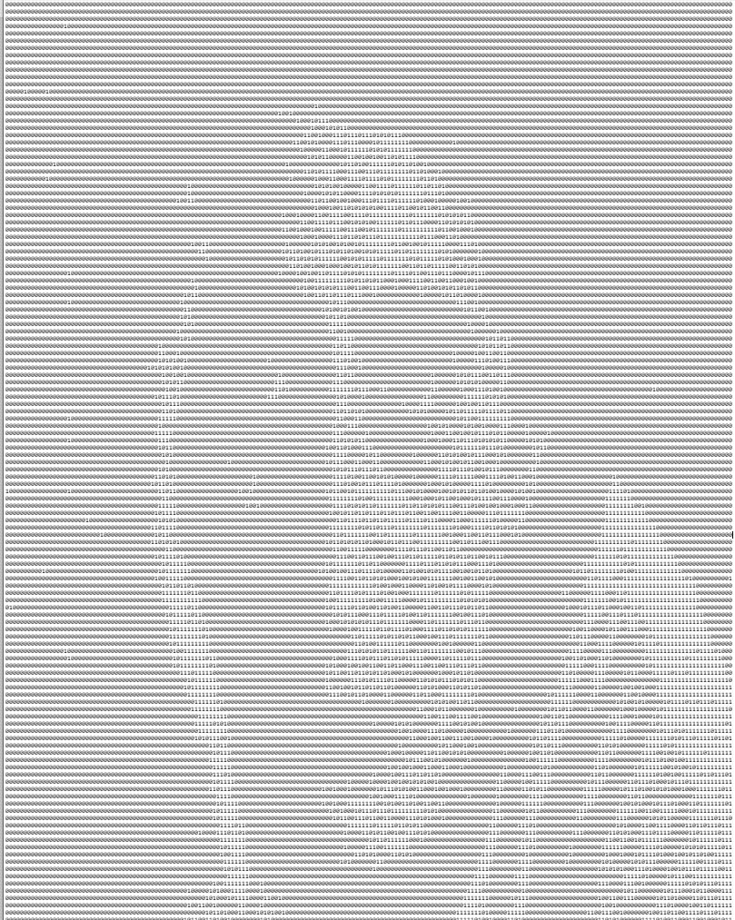
For the video I am looking into FFMPEG. It can export still images every X seconds (ffmpeg -i input.mp4 frame%04d.png) which I could then turn into bits with a simple python or processing code.
Processing also has code to take video and convert it to ASCII : https://github.com/processing/processing-video/blob/main/examples/Capture/AsciiVideo/AsciiVideo.pde
Maybe the best setup would be to have Processing create a series of ASCII text files based on frames from a video, and then put that on the SD card.
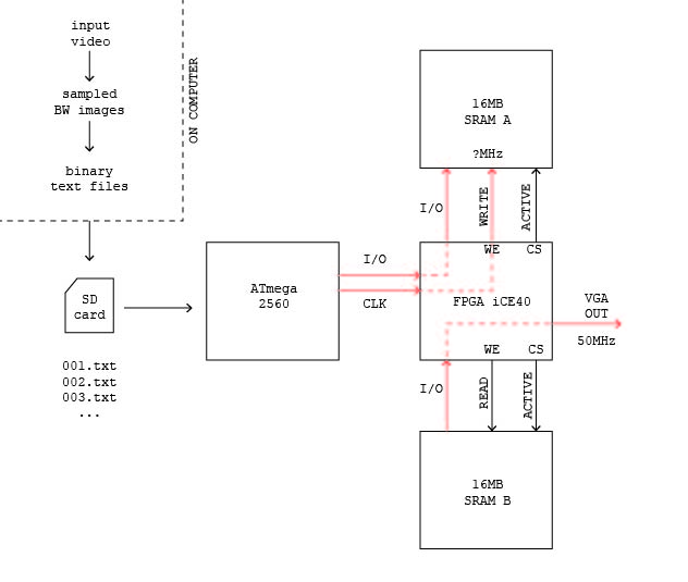
Here is a schematic of how it could work with two SRAM banks in dual banking mode, writing to one while reading from the other and then switching :
******
PROGRAMMING FPGA WITH ARDUINO OR RPI
I had been trying to open the OLIMEX demo code pilot incorrectly. It does indeed work from the command line. I’ll have to test with the MEGA next.
****
An attempt at mixing the pattern generation with the recording to memory functionality :
`default_nettype none

module vga_sync_test(

input wire clk_in,
input wire reset,

input wire rec, // Direction of io, 1 = set output, 0 = read input

//RASPBERRY PI
input wire [3:0] r_in,
input wire [3:0] b_in,
input wire [3:0] g_in,

//VGA OUT
output reg [3:0] r_out,
output reg [3:0] b_out,
output reg [3:0] g_out,

output wire h_sync,
output wire v_sync,

//SRAM

output reg [20:0] addr,
inout wire [7:0] io, // inout must be type wire

output wire cs_1,
output wire cs_0,
output reg we_0

);


wire half_sec;

wire [12:0] random_number_0;
wire [12:0] random_number_1;
wire [12:0] random_number_2;
wire [12:0] random_number_3;
wire [12:0] random_number_4;
wire [12:0] random_number_5;
wire [12:0] random_number_6;
wire [12:0] random_number_7;
wire [12:0] random_number_8;
wire [12:0] random_number_9;
wire [7:0] sine_wave;

wire [7:0] data_in;
wire [7:0] data_out;

reg toggle;

reg [7:0] a, b;

assign io = rec ? a : 8'bzzzzzzzz;

assign data_out = b;

assign data_in[1:0] = r_in[3:2];
assign data_in[3:2] = b_in[3:2];
assign data_in[5:4] = g_in[3:2];
assign data_in[7:6] = 2'b00;

wire display_en;
wire [11:0] h_count;
wire [11:0] v_count;

localparam h_pixel_max = 1280;
localparam v_pixel_max = 960;
localparam h_pixel_half = 640;
localparam v_pixel_half = 480;


reg [1:0] count2; //to keep track of the shifts

wire [11:0] bit_or;
assign bit_or = h_count[11:0]|v_count[11:0];

wire [11:0] bit_xor;
assign bit_xor = h_count[11:0]^v_count[11:0];

wire [11:0] bit_and;
assign bit_and = h_count[11:0]&v_count[11:0];

wire [11:0] bit_nand;
assign bit_nand = h_count[11:0]& ~v_count[11:0];

wire [11:0] bit_xnor;
assign bit_xnor = h_count[11:0]^ ~v_count[11:0];

reg [11:0] out_bit ;


// CS: low to select, high to deselect

assign cs_0 = toggle ? 1 : 0;
assign cs_1 = toggle ? 0 : 1;

//SRAM address counter

always @(posedge clk_in) begin

if (addr == 0) begin
toggle <= toggle+1;
end

if (reset) begin
addr <= 0;
end else begin
addr <= addr+1;

end
end


//REC control

always @(posedge clk_in) begin

b <= io;
a <= data_in;

if (rec) begin
we_0 <= addr[0]; //not sure why it isn't the inverse of addr[0] but that doesn't make the inverse on 'scope
end
else begin
we_0 <= 1;
end
end

//VGA COLOR OUT

always @(posedge clk_in) begin

case(count2)
2'b00: out_bit = bit_or;
2'b01: out_bit = bit_xor;
2'b10: out_bit = bit_and;
2'b11: out_bit = bit_nand;

default: out_bit = bit_xnor;
endcase
count2 <= count2 + 1;
end

//VGA COLOR OUT

always @(posedge clk_in) begin
if (display_en) begin

if (out_bit[random_number_2[3:0]] == 1 | out_bit[random_number_6[3:0]] == 0) begin

r_out <= random_number_2[3:0];
g_out <= random_number_3[3:0];
b_out <= random_number_4[3:0];

end

else begin

r_out[3:2] <= data_out[1:0];
r_out[1:0] <= data_out[1:0];
g_out[3:2] <= data_out[3:2];
g_out[1:0] <= data_out[3:2];
b_out[3:2] <= data_out[5:4];
b_out[1:0] <= data_out[5:4];

end

end else begin

r_out <= 4'b0000;
g_out <= 4'b0000;
b_out <= 4'b0000;

end
end

vga_sync vga_s(
.clk_in(clk_in),
.reset(reset),
.h_sync(h_sync),
.v_sync(v_sync),
.h_count(h_count),
.v_count(v_count),
.display_en(display_en) // '1' => pixel region
);

LFSR random_s(
.clock(clk_in),
.reset(reset),
.half_sec_pulse(half_sec),
.rnd_0(random_number_0),
.rnd_1(random_number_1),
.rnd_2(random_number_2),
.rnd_3(random_number_3),
.rnd_4(random_number_4),
.rnd_5(random_number_5),
.rnd_6(random_number_6),
.rnd_7(random_number_7),
.rnd_8(random_number_8),
.rnd_9(random_number_9)
);

sine_wave_gen sine_wave_s(
.clk(clk_in),
.data_out(sine_wave)
);

tempo tempo_s(
.clk(clk_in),
.half_sec_pulse(half_sec)
);

endmodule
I just realized that I could connect the rpi pixel clock to the FPGA to have a totally synchronized clock between the videos and the graphics ! I can also connect the DEN pin. Not really working currently though.
*****
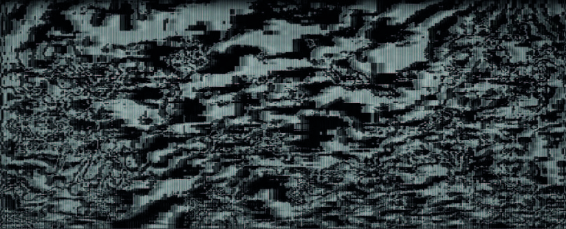
Miniature discovery, if you just take a single bit of information from raspberry pi sending a video, it looks really blocky and cool like a badly compressed video :
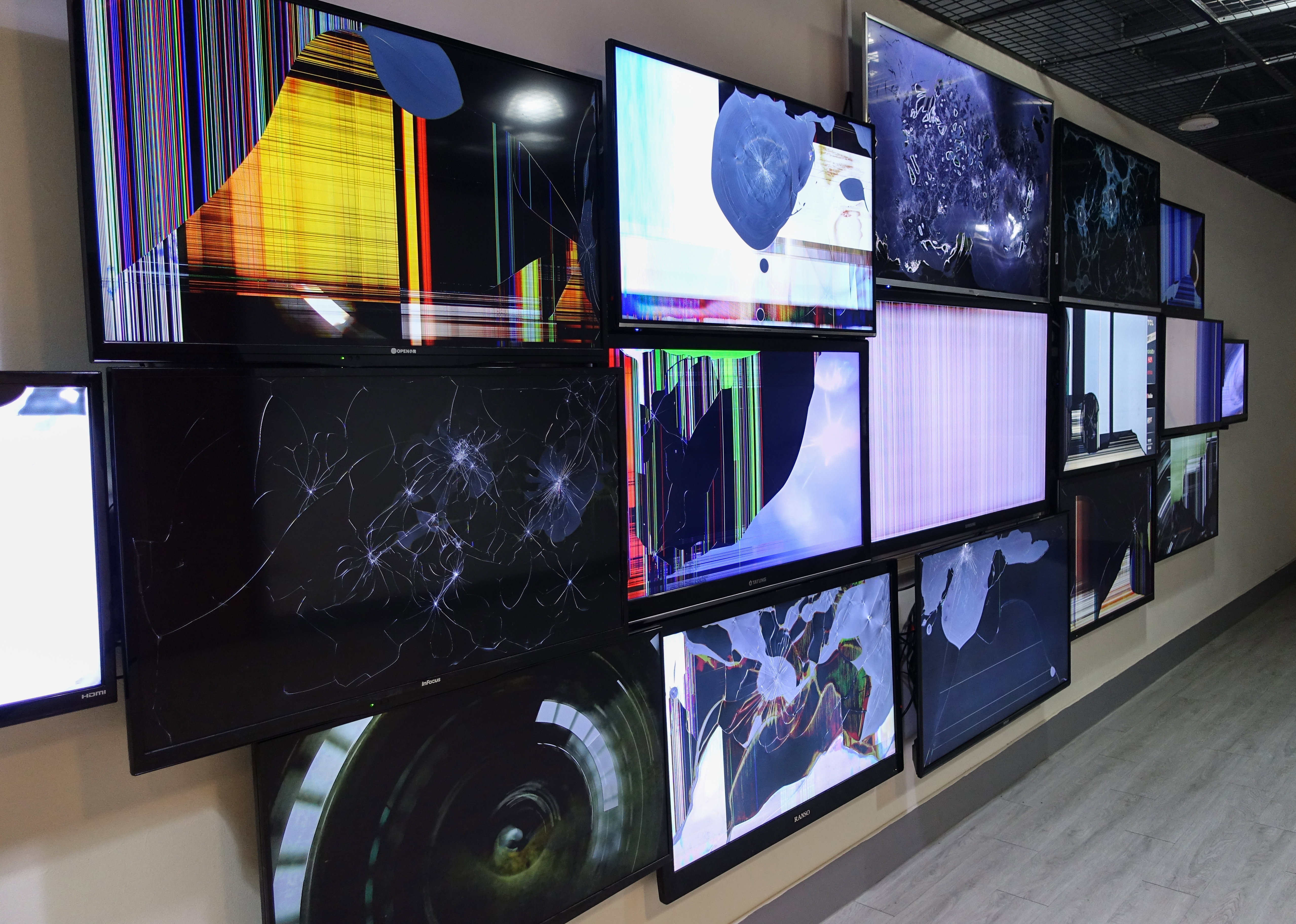
Check out this artist Ni Hao’s broken screens ( https://haoni.art/spin-III) :