This project uses the LTC3105 Solar Harvesting IC from Linear Technologies, an Atmega328P along with a Serial TTL camera and an SD mini card for saving the images.
The plan is to create a waterproof casing for this device and then install it in a nearby forest and set it to take photographs when it sees movement.
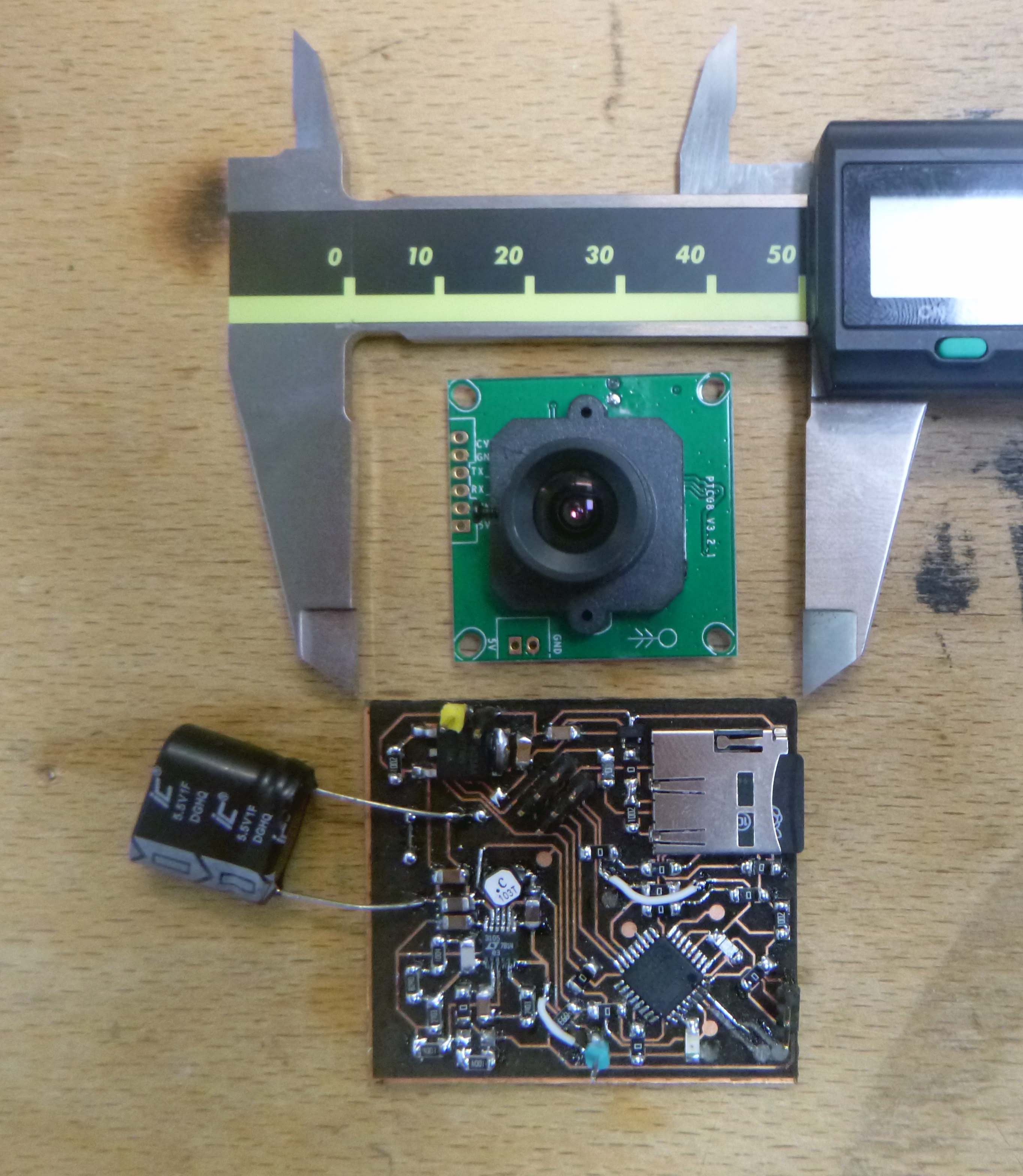
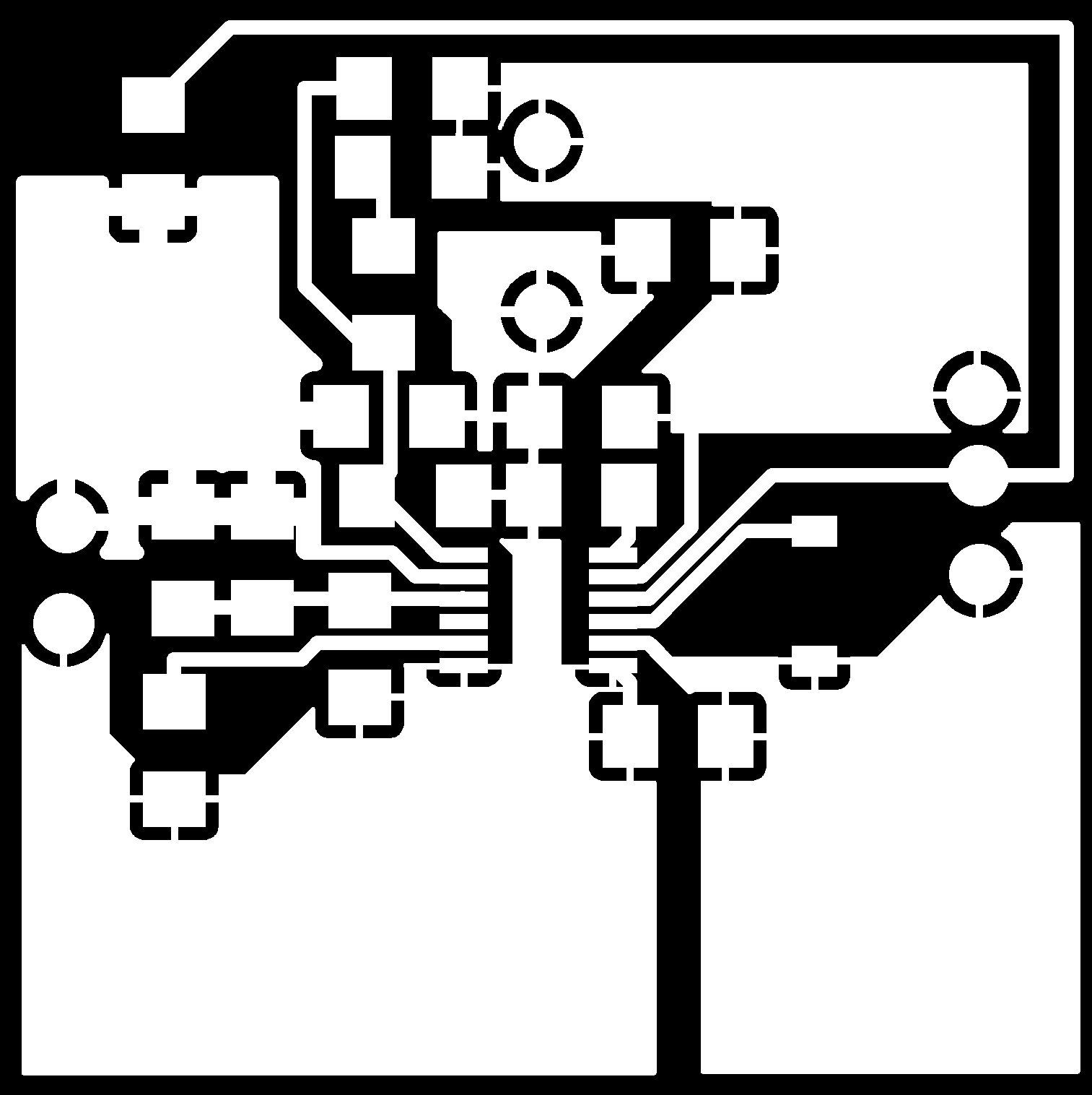
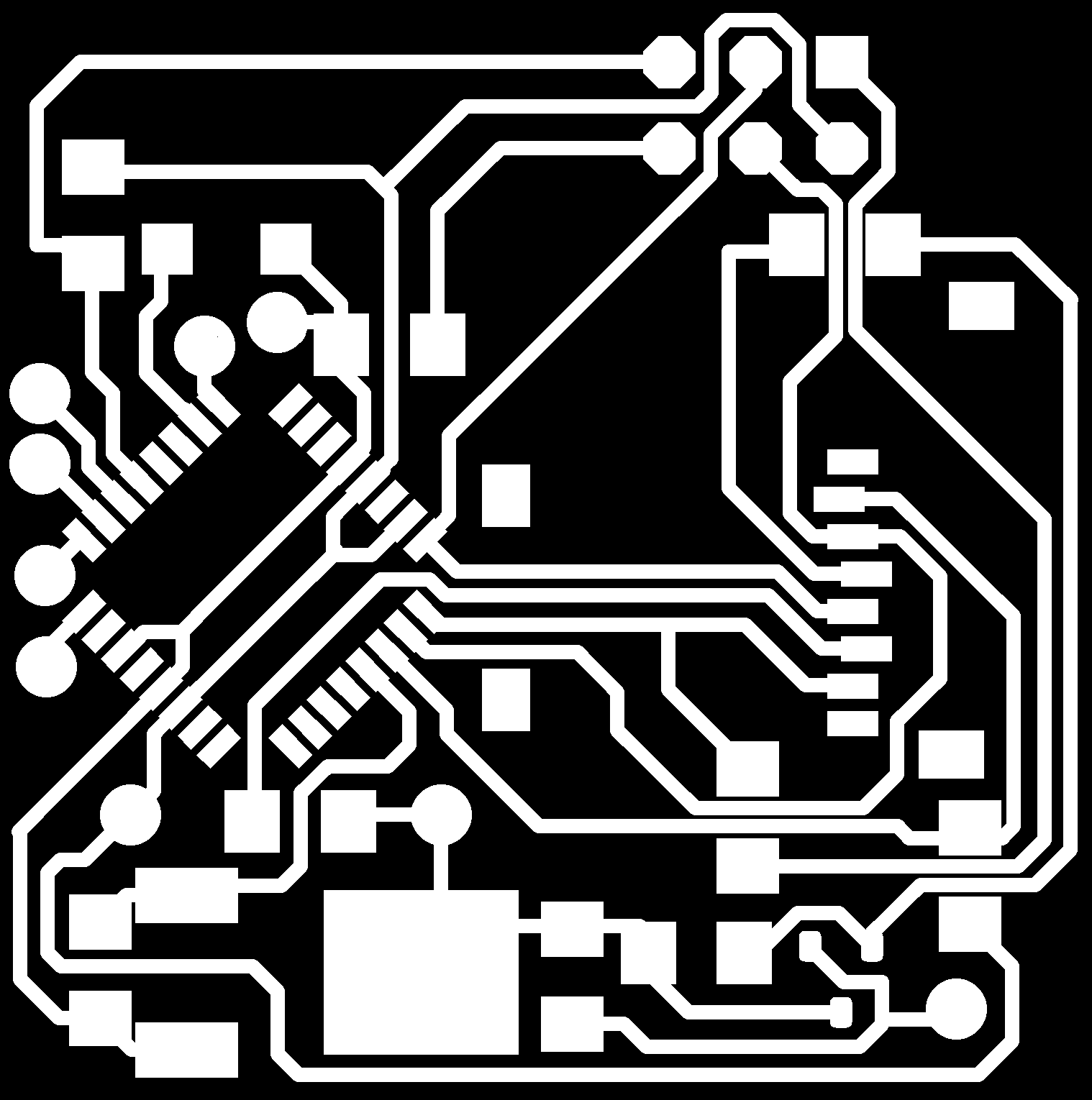
Here is the circuit layout and schematic:


THe LTC3105 can supply between 6mA and 12mA which isn’t enough to power the 3.3V SD card which draws 100mA during R/W at 25MHz mode and 200mA during R/W in 50MHz mode. My attempt to solve this issue is to have a voltage divider step down from 5V (which is powering the camera). The voltage divider uses a 3.3K and a 2.2K resistors and should draw .9mA. The camera has 3.3V TTL logic and draws 75mA at 5V. Both the SD card, the voltage divider and the camera are shut on/off by a MOSFET.
The camera will go on the backside of the circuit board along with a 33x37mm solarbotics solar panel possibly acting as a mini roof. The camera pin spacing is 2mm, not the typical.
I am using two Adafruit tutorials and the relevant preexisting Arduino libraries:
https://learn.adafruit.com/ttl-serial-camera/
https://learn.adafruit.com/adafruit-micro-sd-breakout-board-card-tutorial/introduction
The board took an entire day to engrave and there were still many shorts caused by tiny copper hairs, our lasercutter needs to be serviced:

The first step went smoothly, loading a blink code works fine.

Here things started to get difficult.
- I didn’t place the ICP header perfectly square in the middle of the pins and didn’t use an SMD header so the reset pin pulled off. (I only realized this after I replaced the Atmega328 on the board and wasted a perfectly good chip…)
- I forgot to add a 10K pull-up for the CS, meaning I guess that the SD card could have been disrupting things.
- The soldering of the SD card could have gone smoother, I need to check that the contacts are correct. I am placing the board on a soldering plate and using solder paste that melts at around 130 C.
- I really need a USART connection to be able to debug this and didn’t break out pins RX and TX unfortunately. My improvised solution might be adding noise to the serial communication.
- It appears that when the SD card is plugged in it is not a good idea to program the Atmega328. I get errors when AVR studio writes or reads data.
- Of course don’t forget to set the CLKDIV fuse off so that everything works smoothly with Arduino.

After testing with the SD Arduino libraries I had varied success, sometimes it would pass the SD card initialization but then report the wrong size of SD card. I reformated my SD card and that didn’t change anything. I tried a Read Write example code and that didn’t pass the initialization phase.
I found a serious error in my board, I connected both VDD and VSS to 3.3V but in fact only VDD should go to 3.3V. VSS should be connected to ground.

I can get the Ardiuno SD Read/Write code to at least create a file on the SD card now but it also produced a bunch of USART noise:

I’m not sure if the issues are related to my improvised USART connection or something more fundamental in the circuit.
I put the SD card and the Atmega328 on the same power supply, and also checked the connections between the SD card and the microchip (I added a bit of solder to the MOSI pin which wasn’t passing the continuity test with certainty) and now things seem to be working!


As a quick test it seems that if the SD card and the micro share the same ground everything still works even if the SD card is being supplied with a different VCC.
I added the camera and everything seems to work:

And here is the image quality:

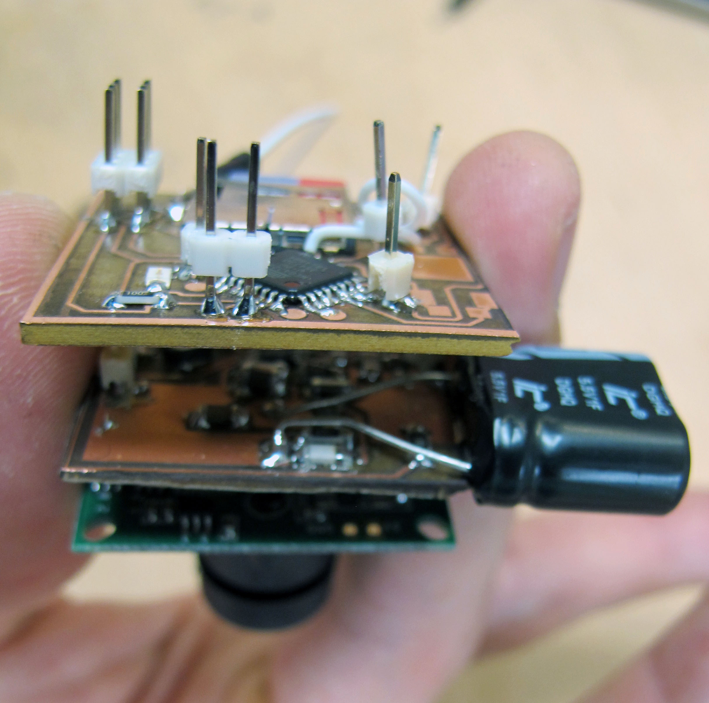
And here’s what the current setup looks like:

Getting to the LTC3105 solar power management part of the circuit and have made some errors:
I want LDO (voltage for microchip) to be at 3.3V so it is at the same logic level as the SD card and camera which it will be communicating with. This means I need a resistor divider to select this voltage level. To get 3.3V I am using 1M and 430K (it adds 1V to the ratio).
To set the Vout at 5V I am using 1M+82K and 270K on the other side.
The solar harvester appears to be working! I’m using a single 1F 5.5V super capacitor which is basically two capacitors put together into one package:


The 1F 5.5V super capacitor I am using isn’t performing great, the moment the sun hits a cloud the voltage falls fast. It might be because of the internal resistance of the cap which is 500mOhms. Contrast this with the wasm 10F 3V supercapacitors I used for the RF solar-powered sensor which had only 34mOhms of ESR. However, the fall in stored power might also be related to the fact I’m asking the LTC3105 to bring Vout to 5V, previously I had only tested to 3.3V. I am also using a solar panel in the 3.5V range which is outside the optimal for this chip.
I am now stuck after having soldered the MOSFET and tried to load the code that would test the SD card after having turned on the MOSFET. This involved also a voltage divider connected to Vout which I am not too sure about. I removed the MOSFET and voltage divider and I am still finding a voltage reaching the SD card mysteriously. I think there may be a short between the 3.3V SD card power and a logic pin for instance.
I think I should have used a voltage regulator instead of a resistor divider, Vout fluctuates quite a bit and this may be throwing off the communication with the SD card.
As a sanity check I powered the SD card with a power supply and the microchip with the super cap/LTC3105 and everything works.
I’m using a 3.3V voltage regulator called the LM3480IM3X-3.3/NOPB which can supply 100mA which is just enough for R/W if the SD card is in 25MHz mode.

The SD card works when being powered from the solar cap if it has a voltage regulator. The VR works up until around 4.3V of capacitor charge.
The camera also works, including in motion capture mode. (All these tests are connected to a power supply simulating the solar panel, I’ve yet to have a sunny day for testing. When I disconnect the power the cap drains super fast but I think this is because I’m using a 1F cap which is leaking heavily. I have also not yet tested the MOSFET to turn on and off the camera and SD card.)

After start up the motion control detects motion even if there isn’t any but then appears to settle down later.
I got several photos of my hand which was waving quickly through the camera’s field which I thought was impressive:

But I also got some strange lighting:

…and at least a quarter of the jpegs were corrupt.
Finished the redesign of the board:
Side one:
Side two:
It has the following improvements over Rev.1:
-A USART friendly plug-in location for debugging.
-A nicer breakout of the pins (RX, TX, MOSFET GND and VCC) which need to go to the camera on the flip side (they can be bridged with bent pins)
-A 10K on CS line
-A resistor divider to set LDO to other than 2.2V.
-Corrected SD card Vcc and GND connections.
-A 3.3V voltage regulator for the SD card instead of the resistor divider.
-Generally increasing the size of the board and making certain areas a little less squeezed.
-Not a reset button, as there was not enough space, but a RST pin which can be easily touched to a nearby ground pin.
-A set of traces and a header for easy installation of the camera on the back of the board.
The lasercutter is cutting beautifully:

But when I flip the board over to flip the backside I am cutting through and creating holes:

This one barely survived:

I had similar issues with this board unfortunately.
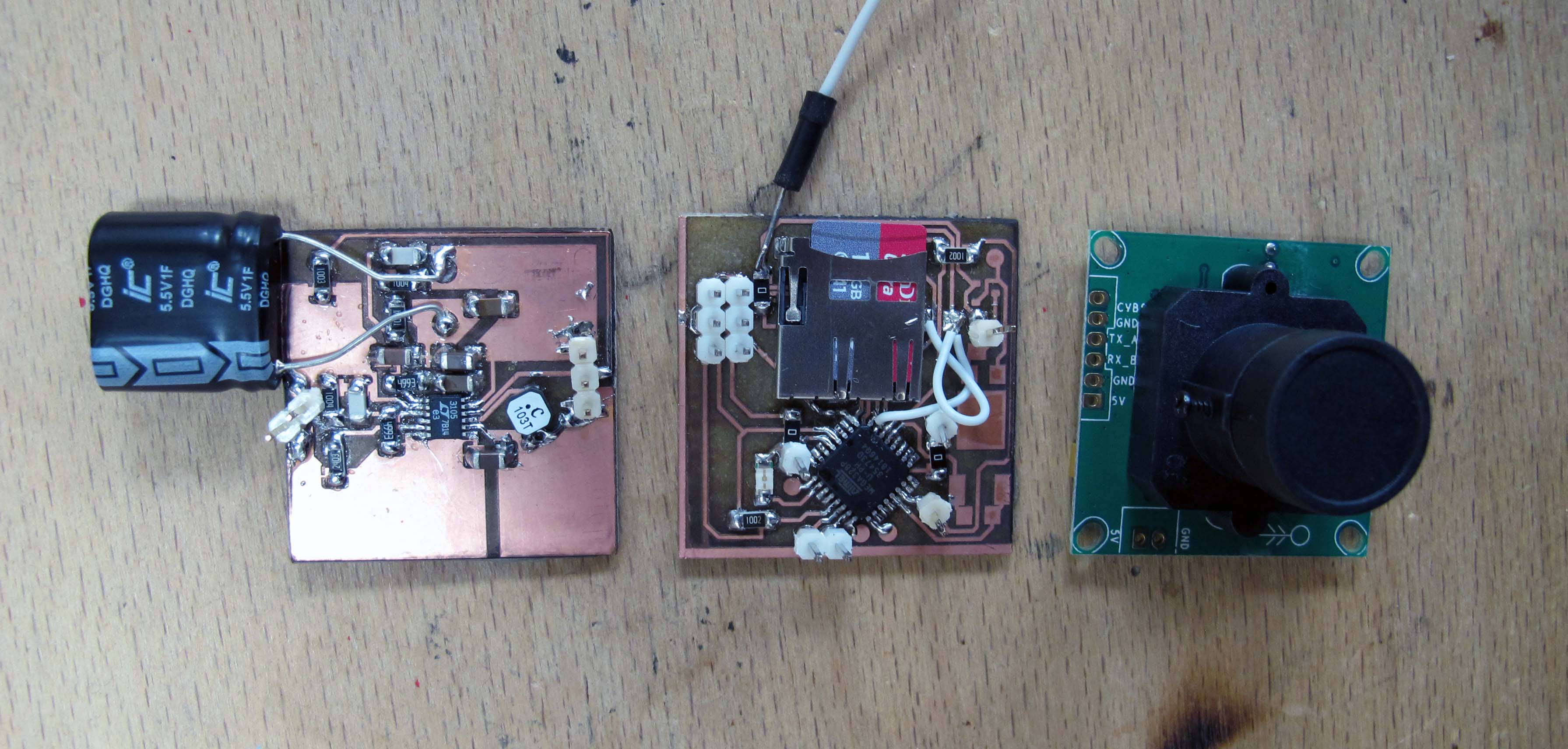
I jumped ship and made a modular version, thinking that this would be fool proof:
Tiny aside: Wow, a camera which gets energy from the same light it is recording! https://www.discovermagazine.com/technology/this-camera-is-powered-by-light