The github for this project :
https://github.com/merlinmarrs/tournesol
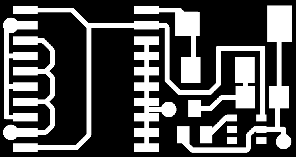
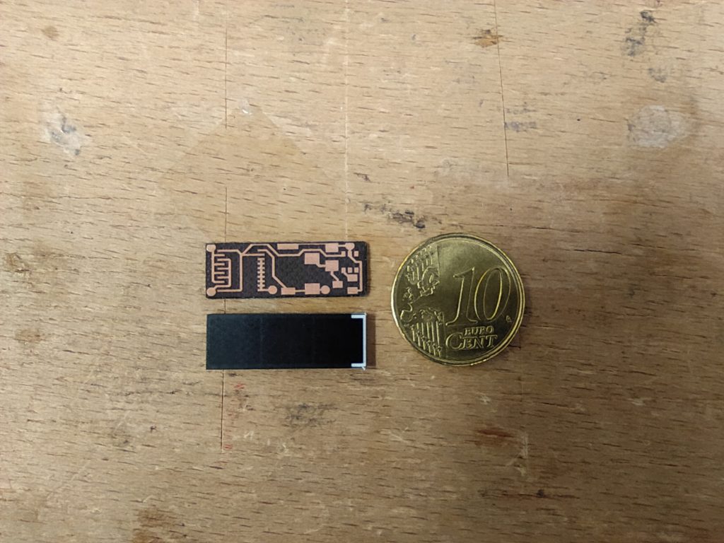
I’ve made the PCB for with the 74AC240 based on this design from http://www.smfr.org/robots/robot_images/dualsolarhead_schematic.png :
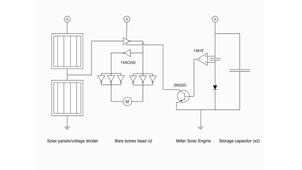

Hoping that it works better than the 540 version with the solar midpoint.
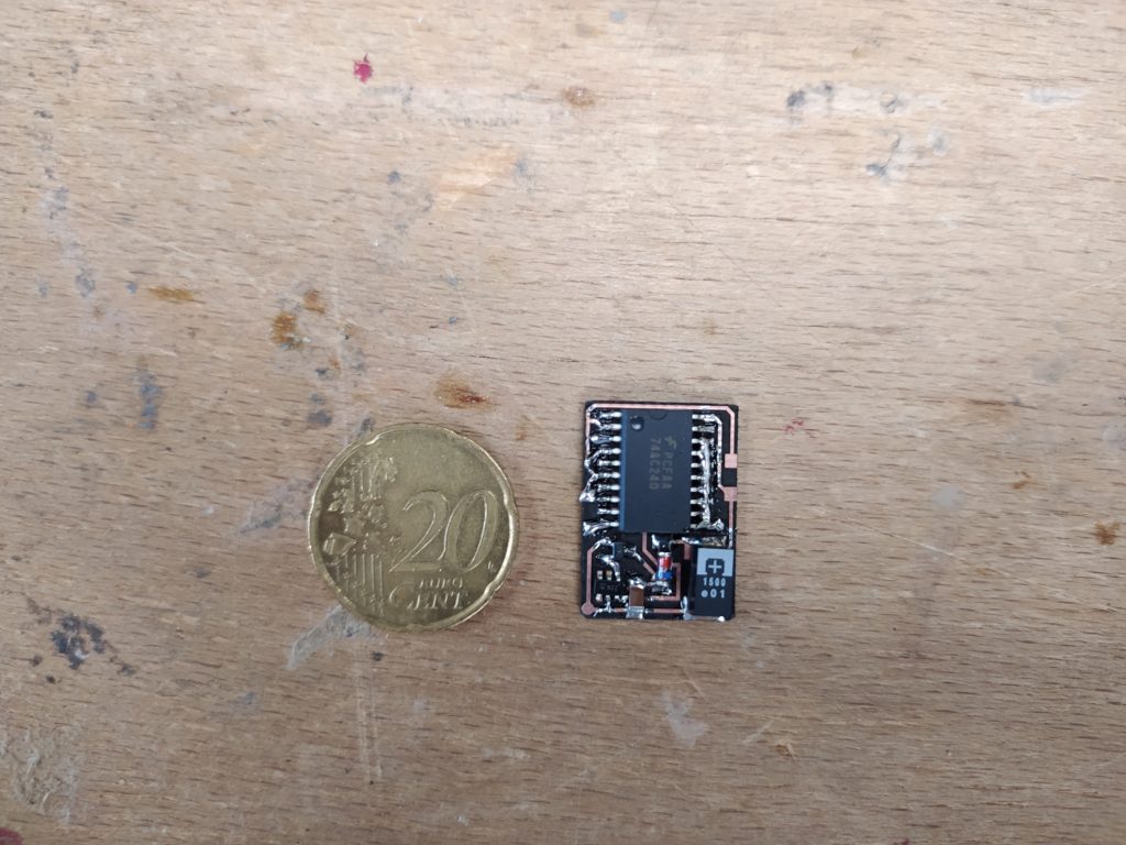
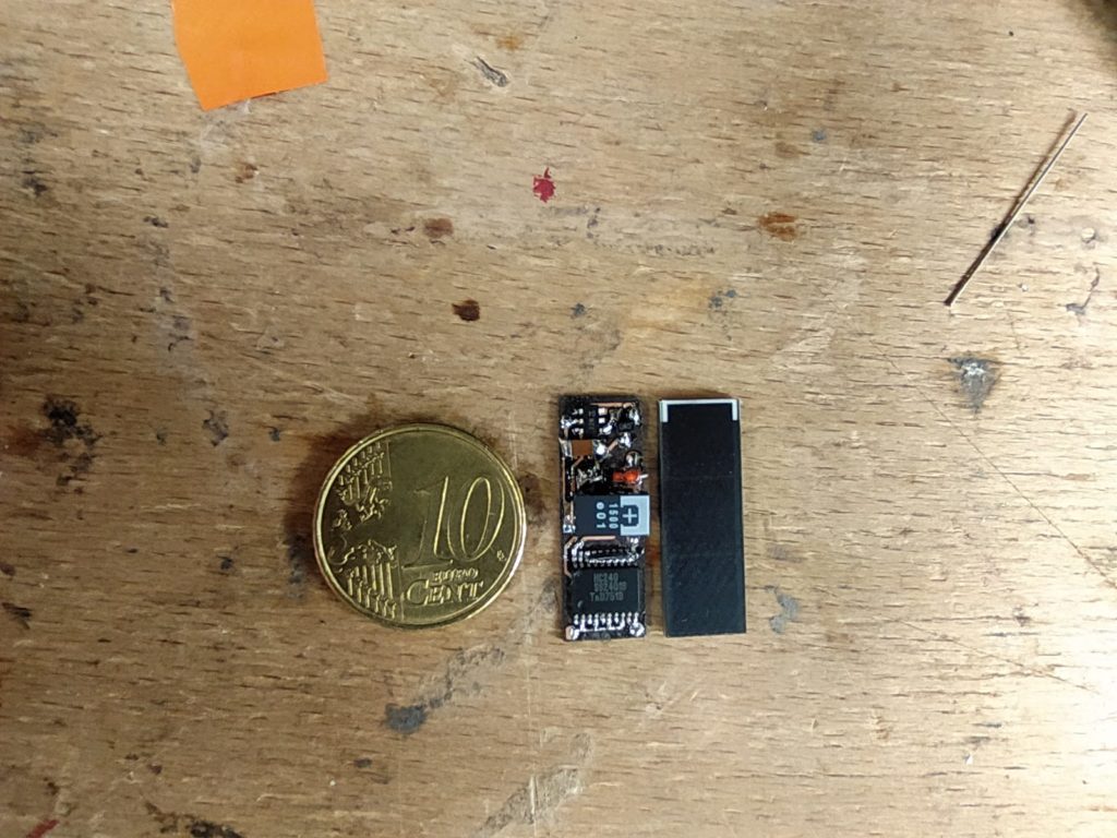
IT DOES! It is far more responsive and efficient and works with the solar panel! It has a funny quirk where it will first turn the wrong way then correct itself in one direction though…Next i’ll make it on a super small extra compact board and try the other circuit option:
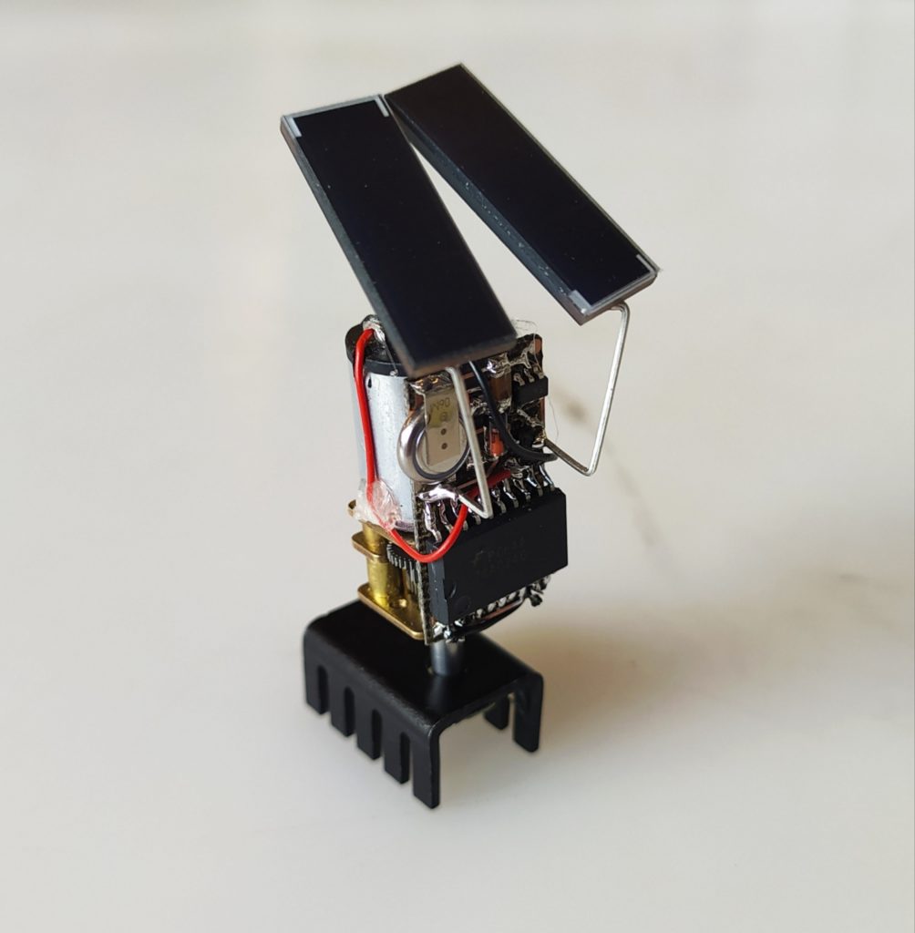
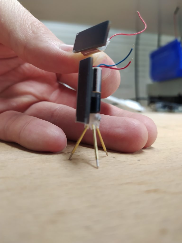
It’s much more compact that the previous version. The photodiodes could be removed to make it even smaller. It took me around 25 minutes to assemble at a comfotable speed. By far the least efficient element of the assembly is the braided wire which is causing mini shorts :

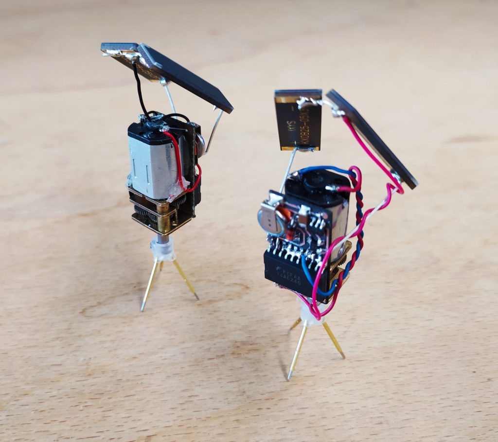
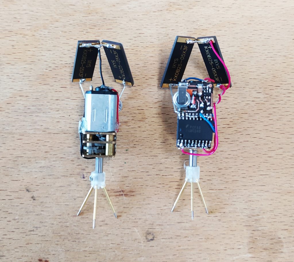
There is already some interesting interplay with the two machines side by side…
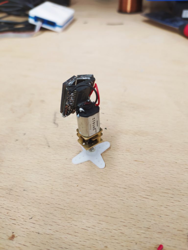
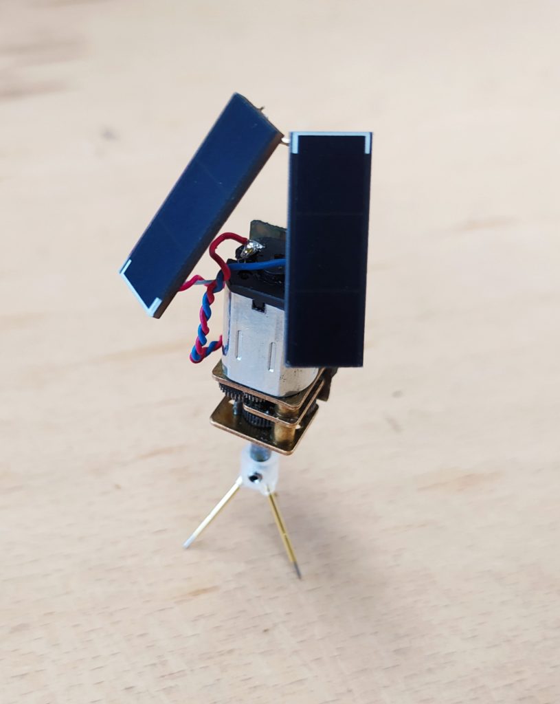
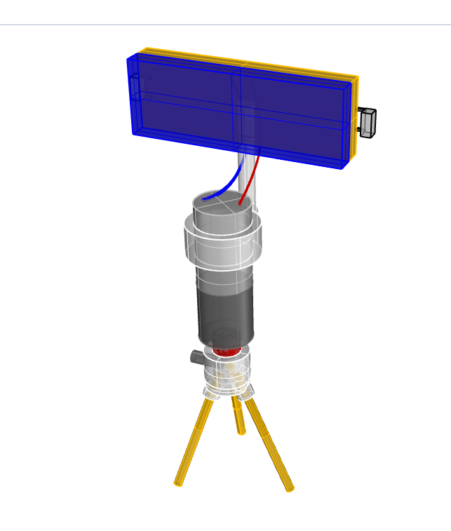
3D model of fancy motor version:
Here’s a version with a tiny gear motor. The motor appears to lock up at low currents however so it doesn’t work super well. It’s also very difficult to attach the motor axle to the bottom platform.
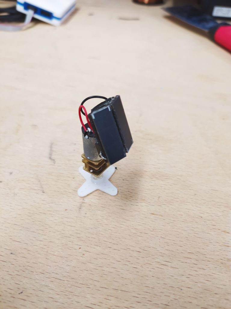
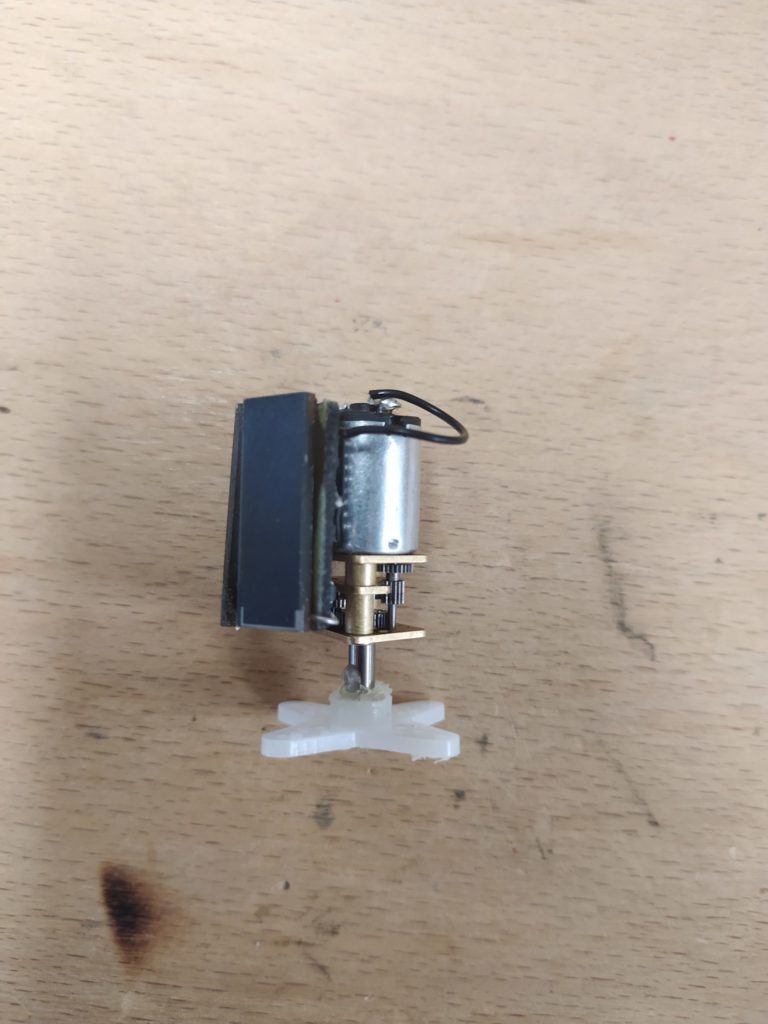
With the metal gearmotor it works much better:
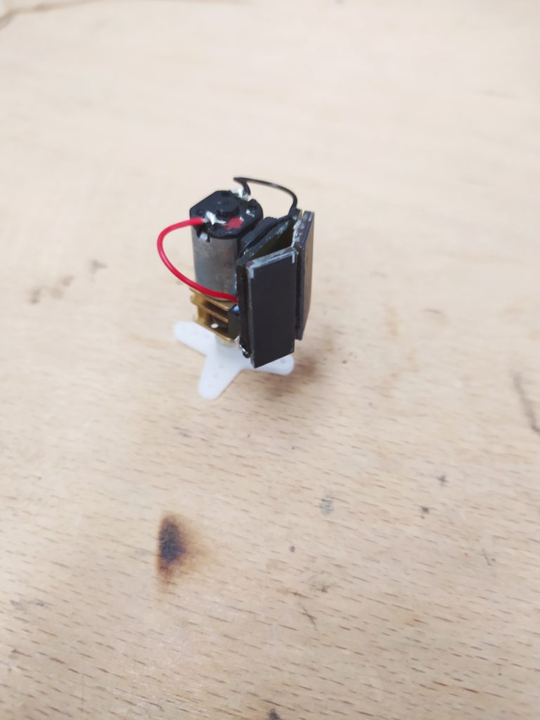
And this version with the panels lower down:
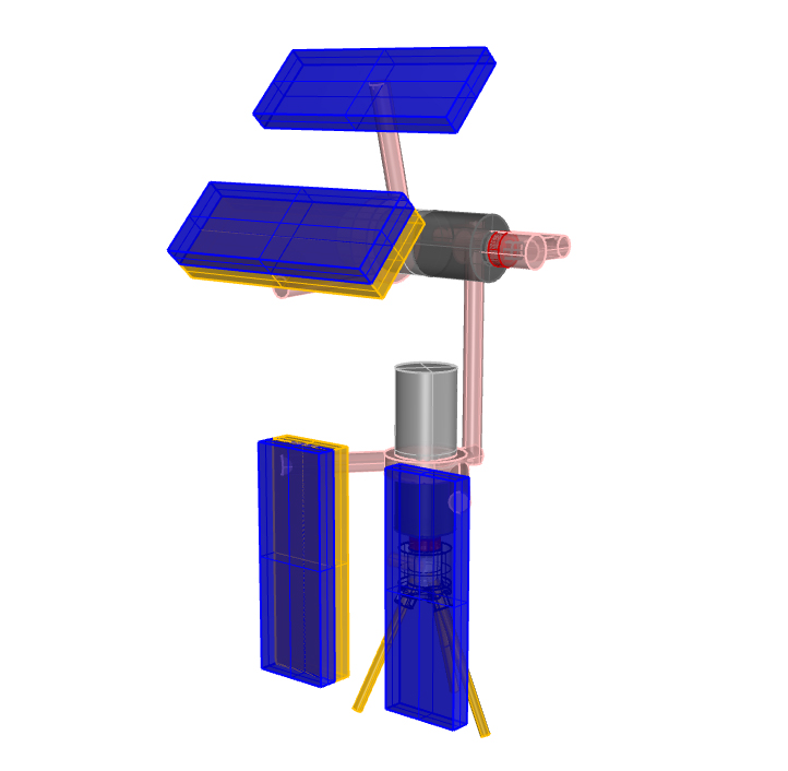
Here is a tall version: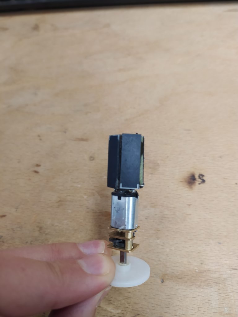
Here’s a compact design with a “flipper” arm:
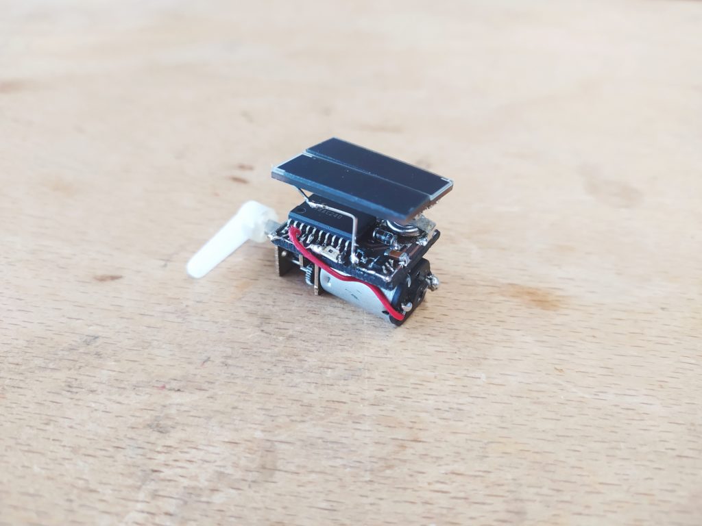
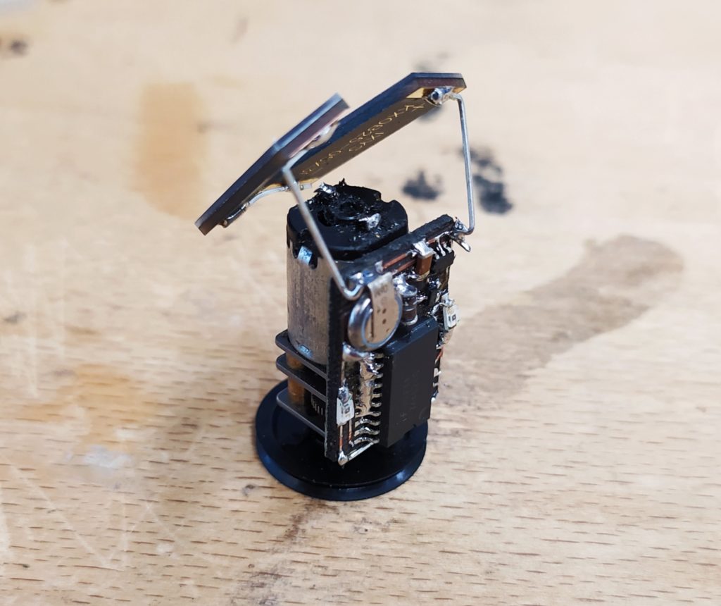
The idea of pulling the solar panels from the board, exposing the electronics and creating the tilt naturally.

The little metal cap is actually a nice part of the look of the machine:

![]()

I have made the board thinner so that it fits perfectly over the gear motor:
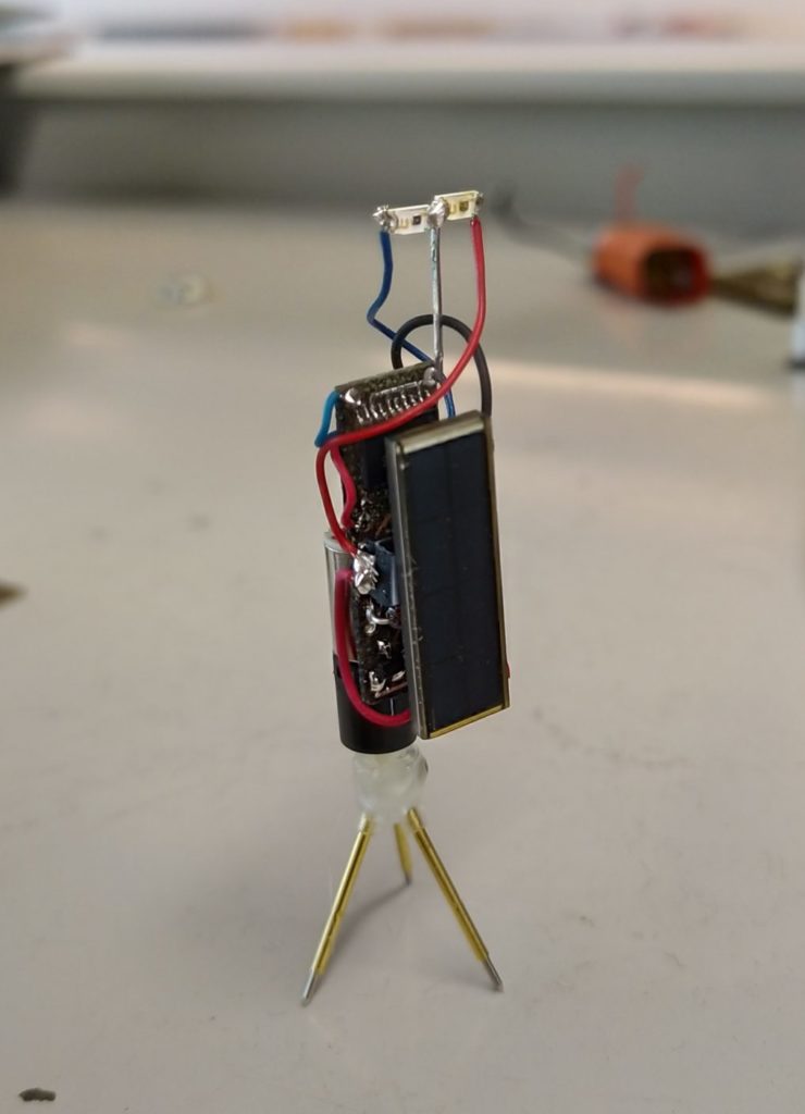
Here’s a shot of it looking pretty:
Llama edition (it’s a heat sink). This photo makes me think I could have fun with shadows like in the 1970 Il Conformista film:

I see a monocled mustachioed Monopoly man here somehow:
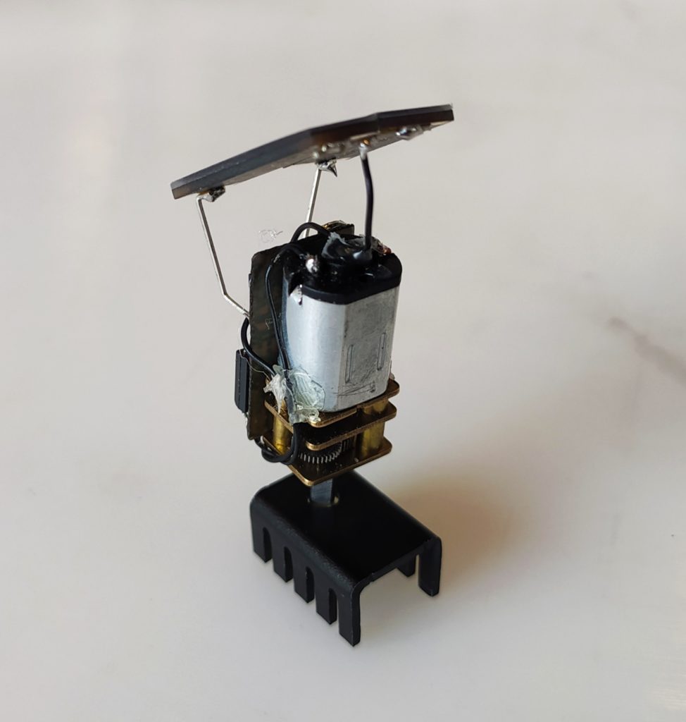
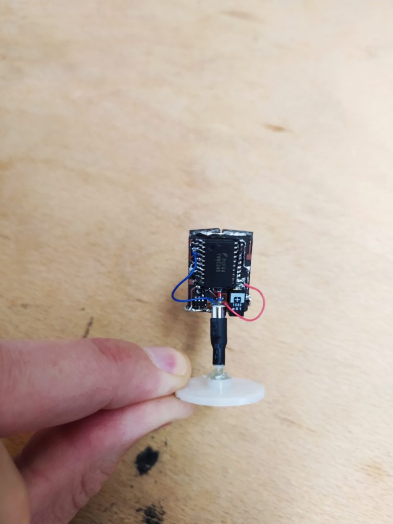
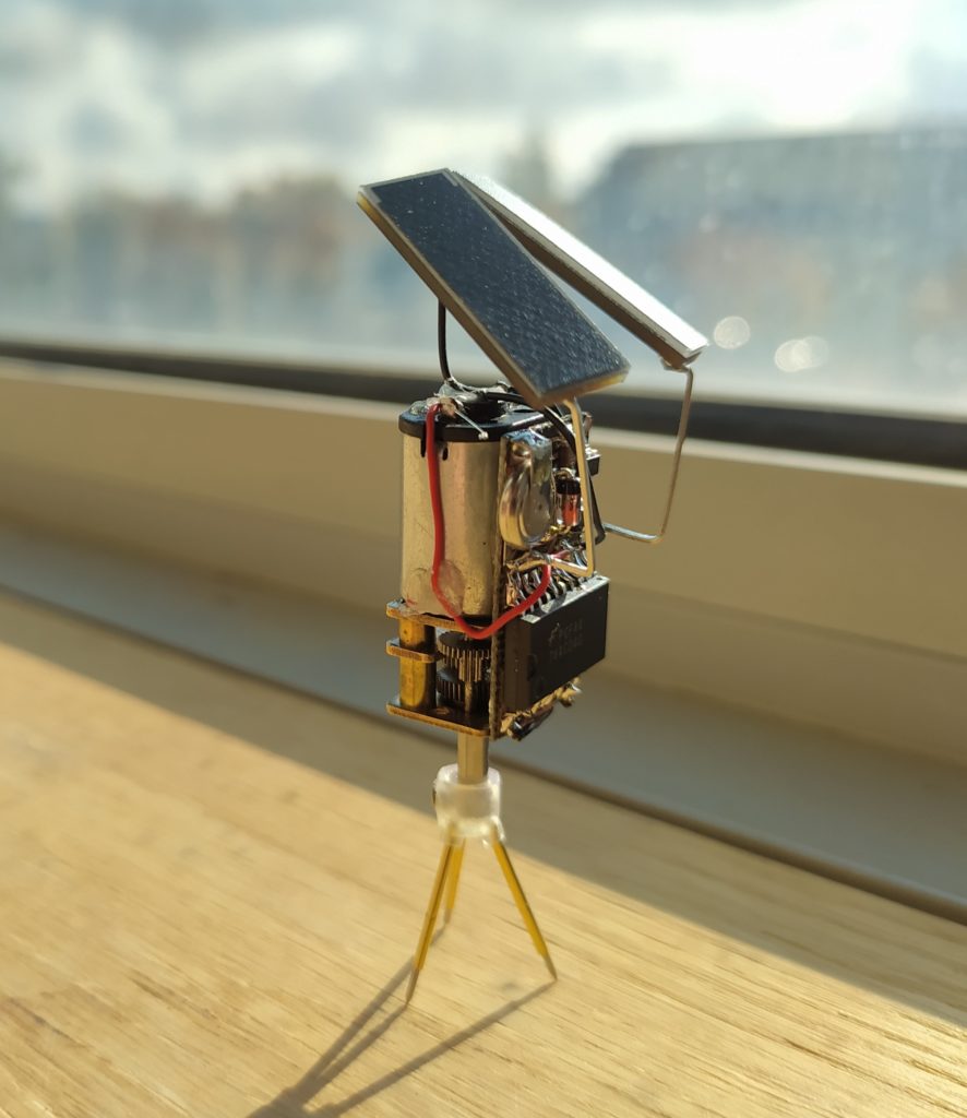
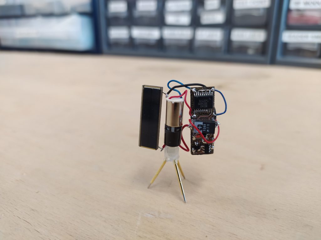
This idea distributes the things to look at around the machine (one side has solar panels and the gear motor, the other has electronics and the underside gold lettering on the solar panels). When the machine is facing the sun we get to see the electronics. I guess the electronics is also sheltered from the heat of the sun a bit?:
Here are some feet ideas for the resin printer using small set screws and (in the right model) Pogo pins:
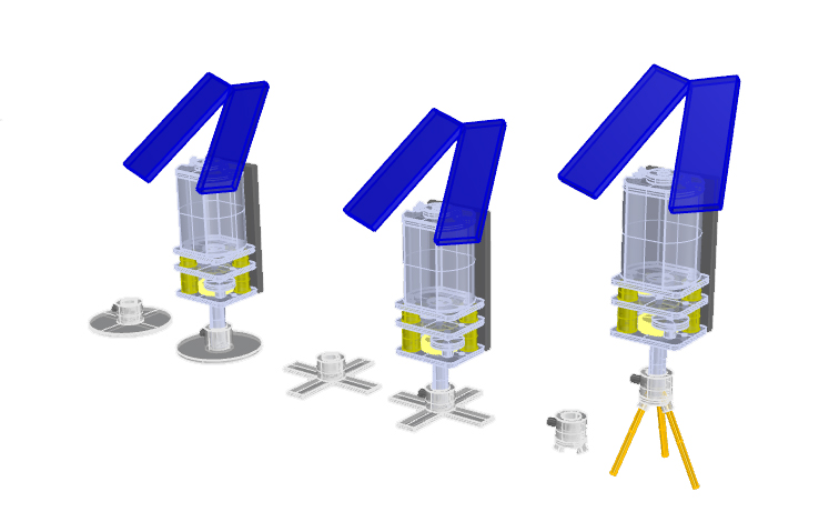
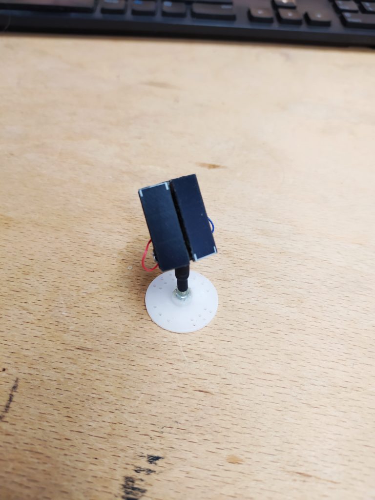
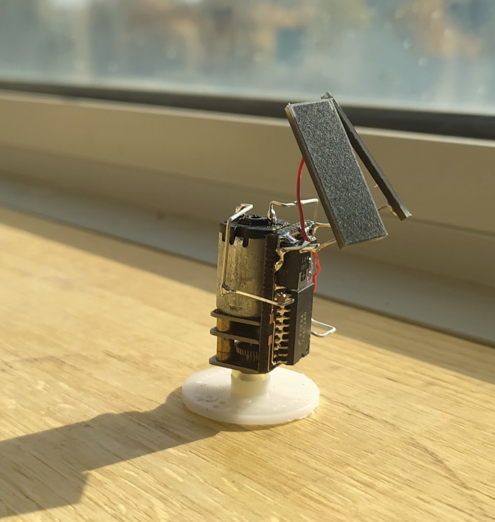
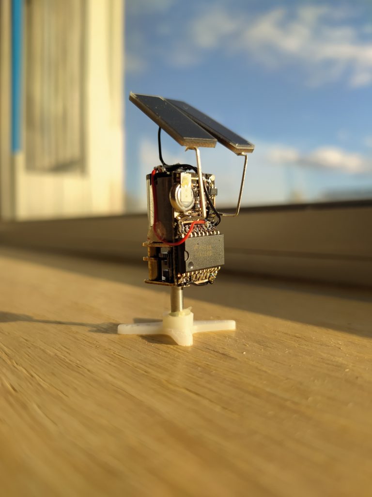
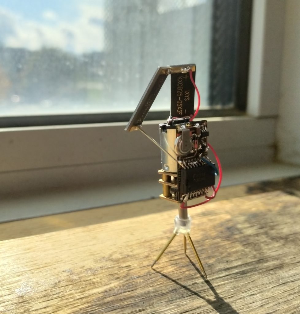
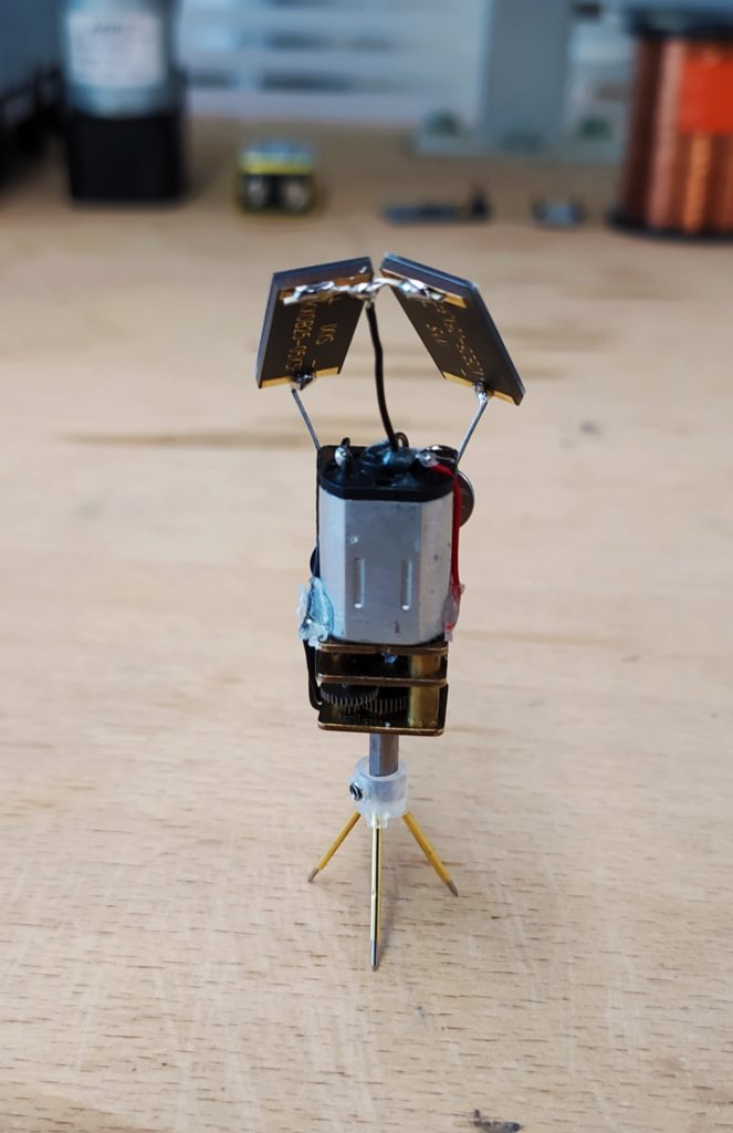
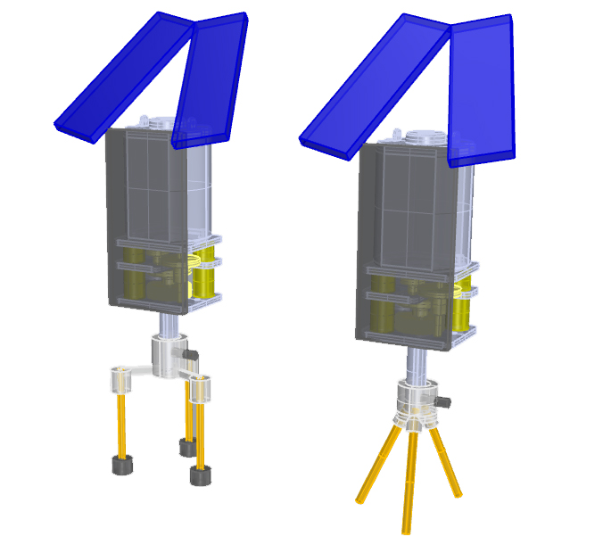
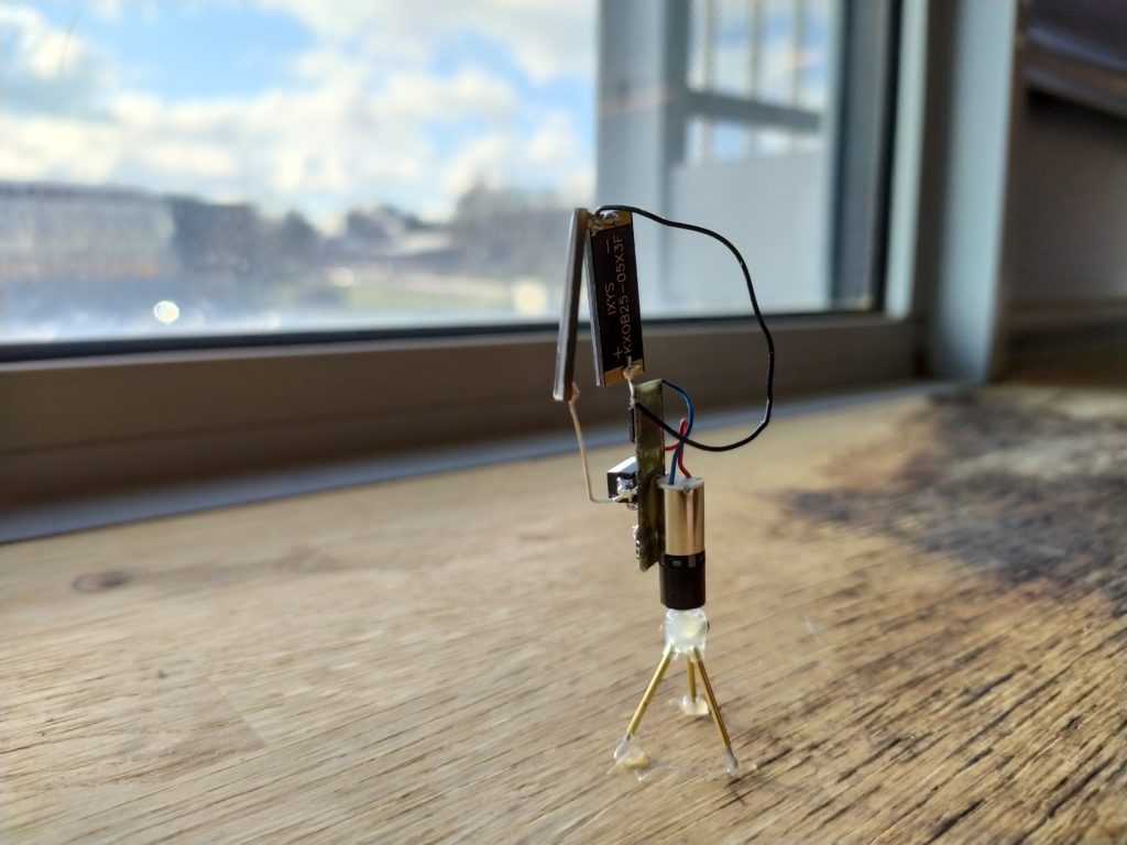
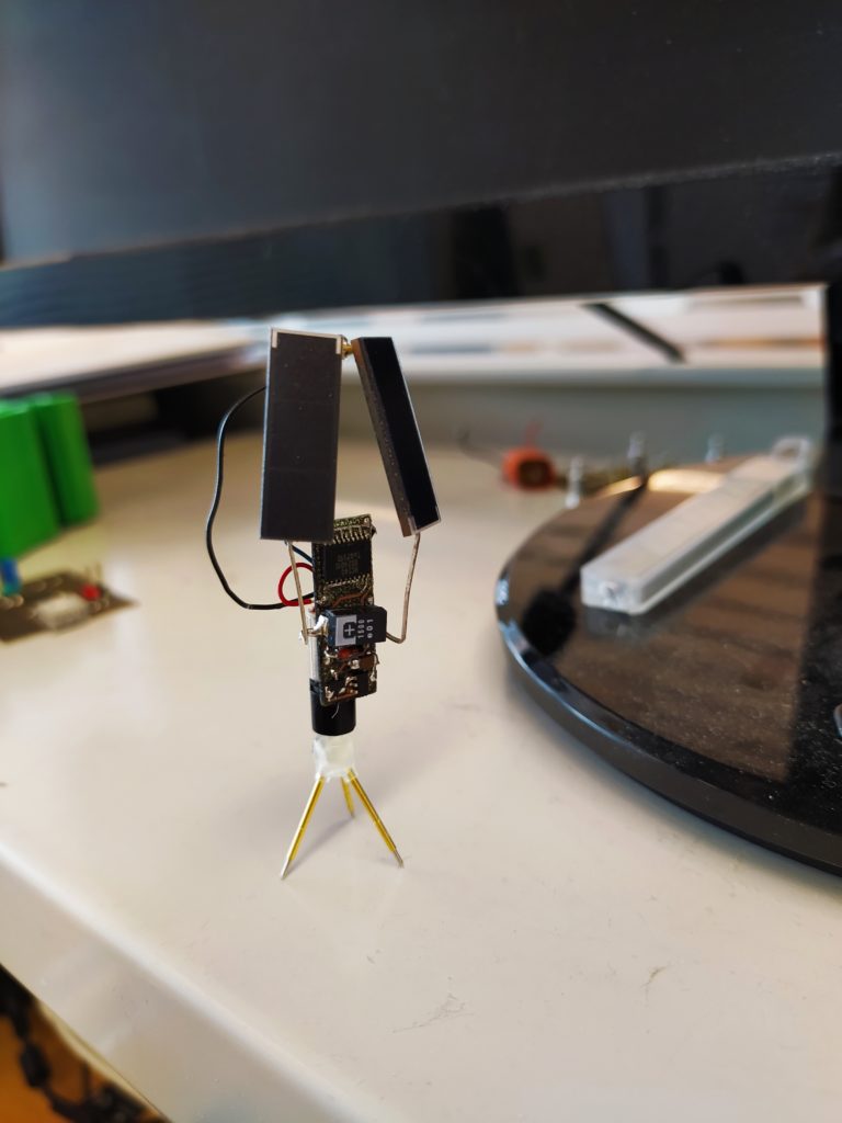
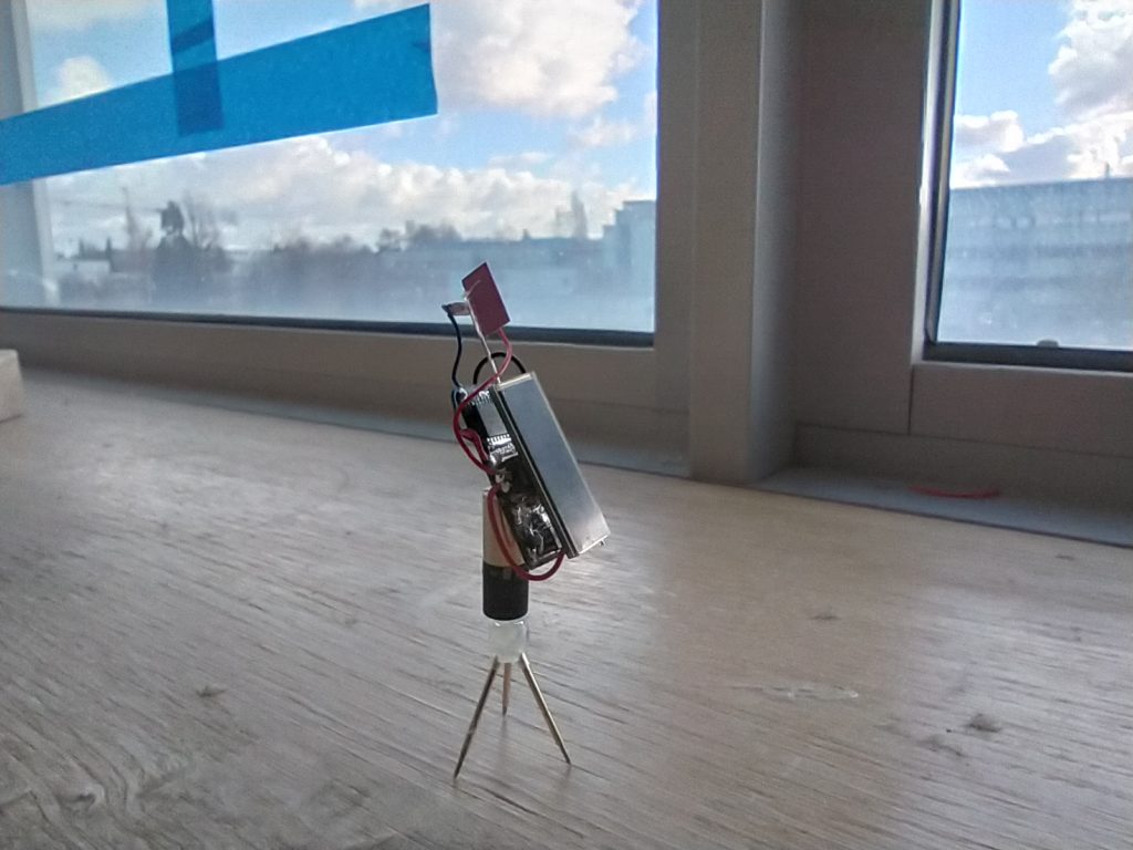
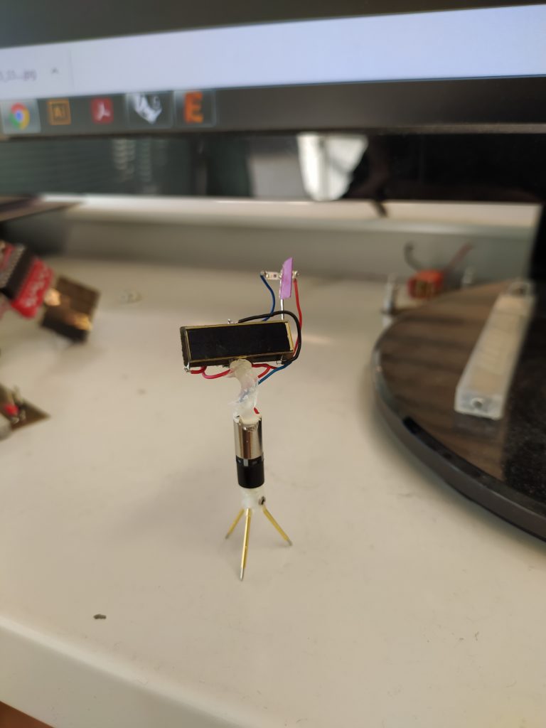
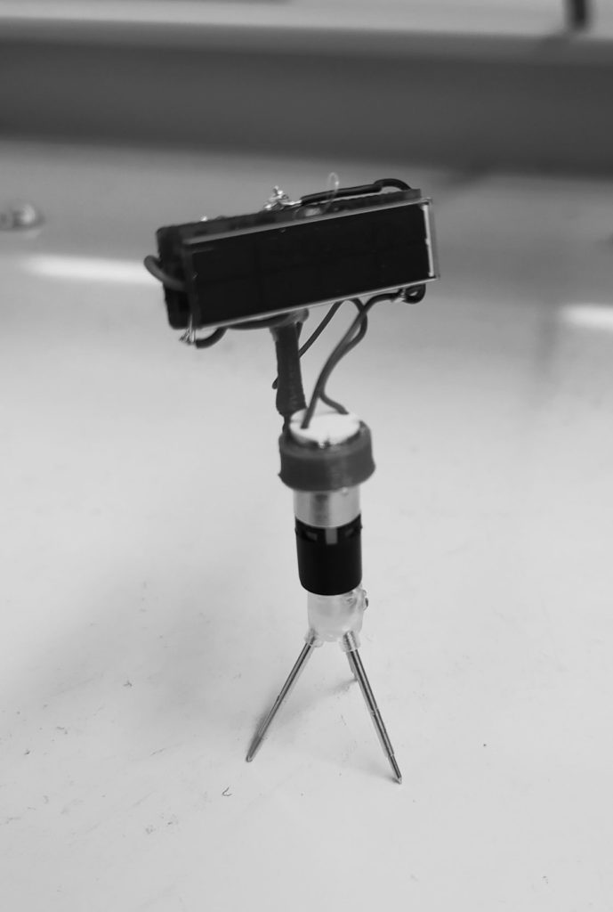
Here are two versions of the tripod design. One has the electronics as a backpack and hides it from the sun, the robot has two faces. The other has the “face” of the robot face the sun, in one photograph the whole robot is visible.
Version 1: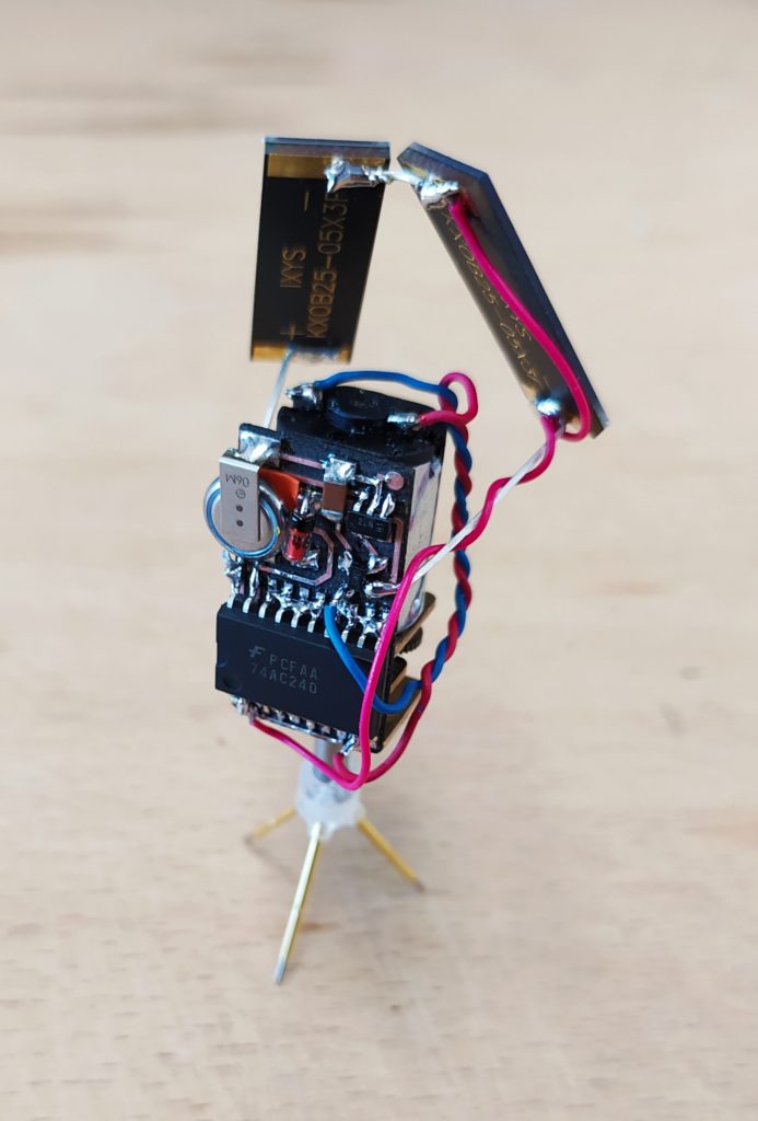
Version 2: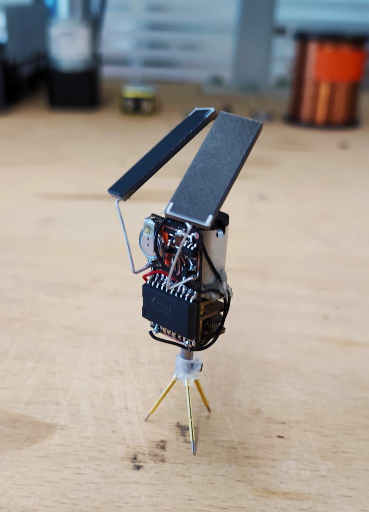
****
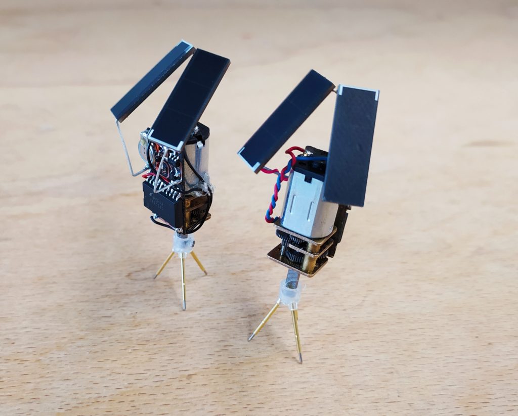
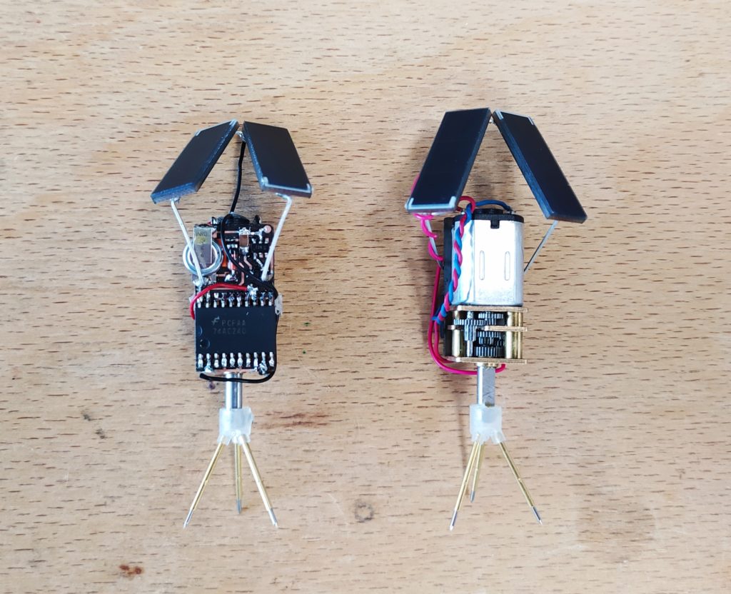
Side to side comparisons:
Another idea for pogo pin feet using the crowned tips:
***
I made the barebones circuit in extra slim also:

debugging the previous version, it appears that the solar panels are indeed producing the expected voltage and current (2 x 1.67V, 18.4 mA), the voltage trigger and mosfet are working, the capacitor is charging, and the voltage to the motors is spiking. However the motors aren’t so much turning as twitching. The motors appear to be identical to others that are working however. Changing the capacitor from .22F to .15F changed nothing.
EDIT:
I had another stab at this:
I noticed that the charging and triggering part of the circuit appeared to be working but that the motor was not firing. I assumed then that there was a soldering problem on the 74AC240 pins somewhere. I tested a copy of the same boards from the same batch to see if there were any problems with the etching itself, they all seemed good with no shorts and clean traces. I tested a blank 74AC240 as well and found that the only pins that were internally connected were 9 (Y1) and 10 (GND) – though I’m not sure why this is the case. I took a voltmeter to measure if there were any shorts between the pins on the IC and found that everything was mostly normal. Looking under the microscope it occured to me that the problem might be that the pins of the IC aren’t fully touching the pads below as they appeared to have been soldered quickly. In order to assume myself that everything was indeed well connected I reheated each of the pin connections and retested that I didn’t introduce any shorts. I then switched out the larger motor for a more efficient smaller DC motor. Testing with artificial light I now have normally functionality!
The second malfunctioning solar head has a different issue: It charges up fine from having no power and spins the motor no problem. But after a few times it stops triggering at hovers around 3.6V…I resoldered the connections and had the same issue. The voltage trigger appears to be triggering despite the voltage staying high. In the end I switched the bigger metal gearmotor for a small vibe motor and it worked just fine. I think I can conclude from this that the circuit I used is not suitable for the metal gear motors but works fine with smaller ones.
I am now looking into making this circuit even smaller using TSSOP-20 packages of the 74AC240 and maybe 0603 smd components too. I plan to make this double sided and to have the boards made at PCB way after testing a prototype circuit in the lab.
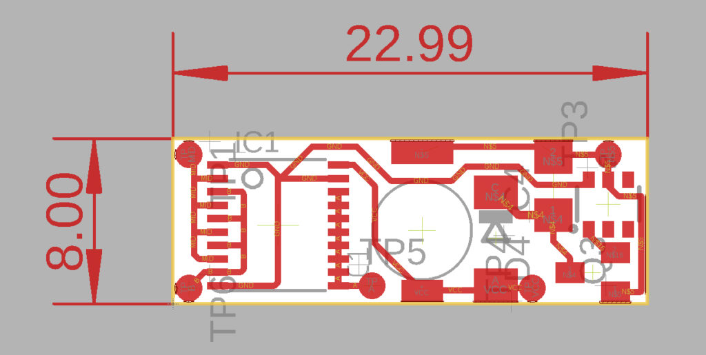
The circuit works fine after I had to resolder some of the IC pins to the pads (they seem to hover just above sometimes despite the soldering) and fixing a short between the two sides of the MOSFET by lifting up the positive side of the SMD cap up.
Testing with a single 3.4V panel and…it turns! I’m going to try to add the light detection now.
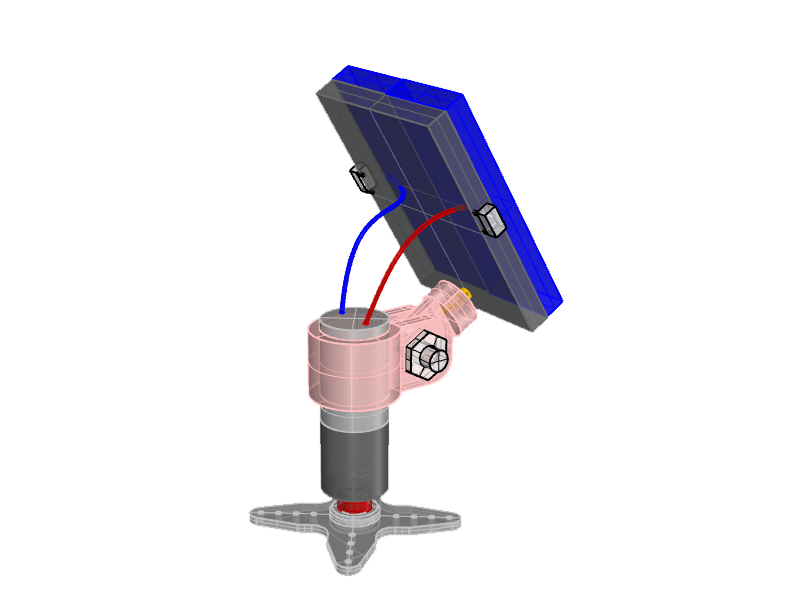
And this is how it could be integrated into the 2DOF design:
This is a second option which would involve probably halving the above circuit and making it double sided.
Another idea is to see how far this minimalism and miniturization can go, for instance with a single solar panel capable of charging up the cap to 3.3V ish. It could be 1DOF or 2DOF. Testing with the power supply with 4,46V @ 5,9mA it works no problem with the small gear motor. We’ll see if that’s the case with the actual solar cell soon.
Monocrystalline Solar Cell 24.5mW (4,46V Current – Short Circuit (Isc) 5,9mA)
https://www.digikey.fr/product-detail/en/anysolar-ltd/KXOB25-01X8F-TR/KXOB25-01X8F-DKR-ND/10127250

Monocrystalline Solar Cell 26.3mW 5.53V:
https://www.digikey.fr/product-detail/en/anysolar-ltd/KXOB25-02X8F-TR/KXOB25-02X8FDKR-ND/9990483

Here is what it could look like 1DOF:

…and 2DOF:
If the solar panels are a bit offset from the boards then the light sensors could be directly on the board and not need to be offset themselves from the board.
****
I actually have one of these lying around to test the one panel idea (3,4V
@ 4,4mA):
https://www.digikey.fr/product-detail/fr/ixys/KXOB22-01X8/KXOB22-01X8-ND/2754274
Here it is working! (remember that the “GND” side of the photo bridge actually connects to the ENABLE of the 74HC240)
some other panel configurations:
I could have the light sensors on either end.

A little higher up…
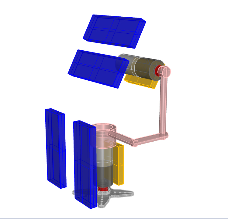
Satellite inspired:
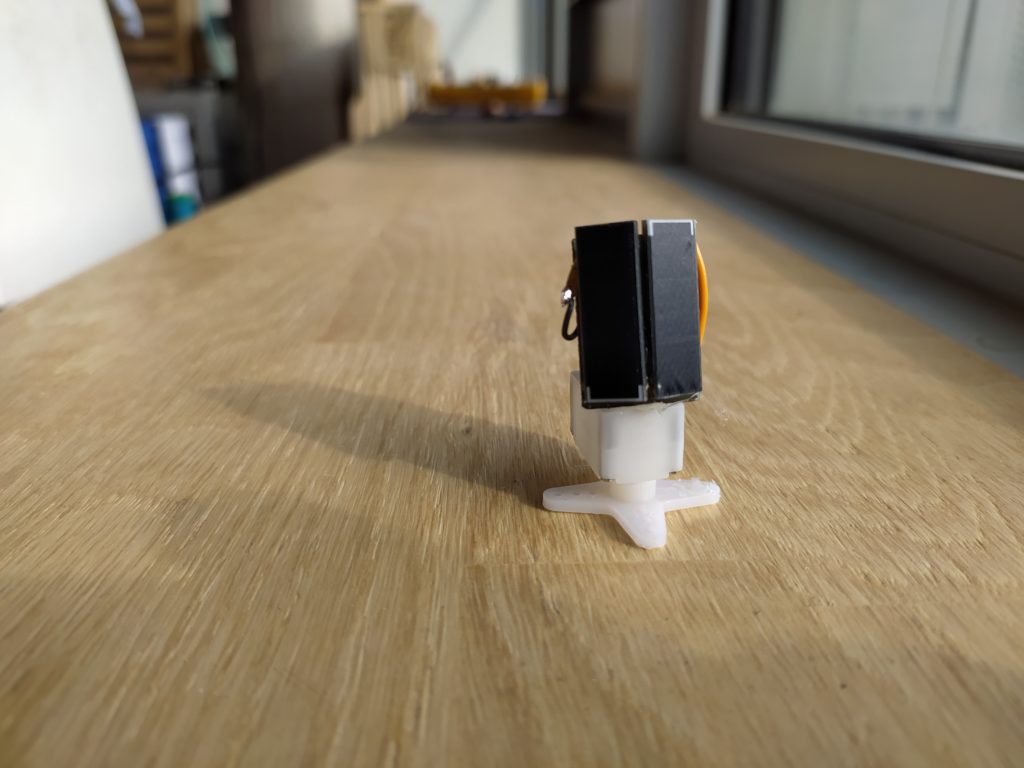
Here’s a quick 3D print:
Not even sure if adding another DOF will have a big effect, over the course of a day how much will it actually tilt up or down?…