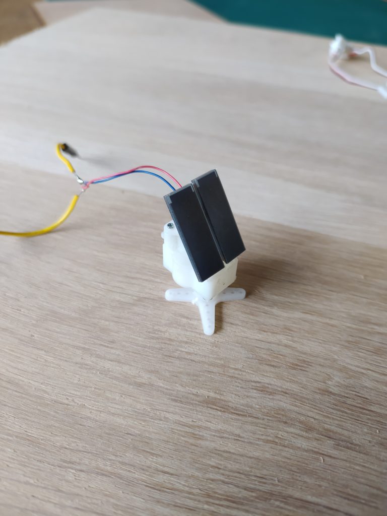
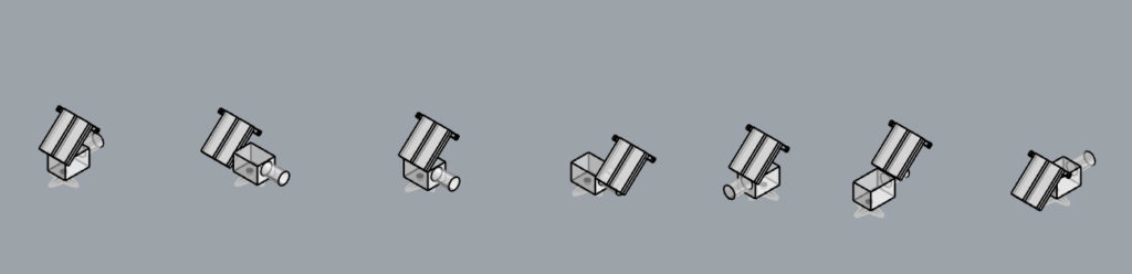
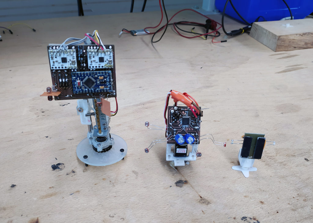
Another idea is to start with the actual solution (two small servos) and make it look better. It’s sturdy and already balanced. It just needs a hinge and a tilting arm:
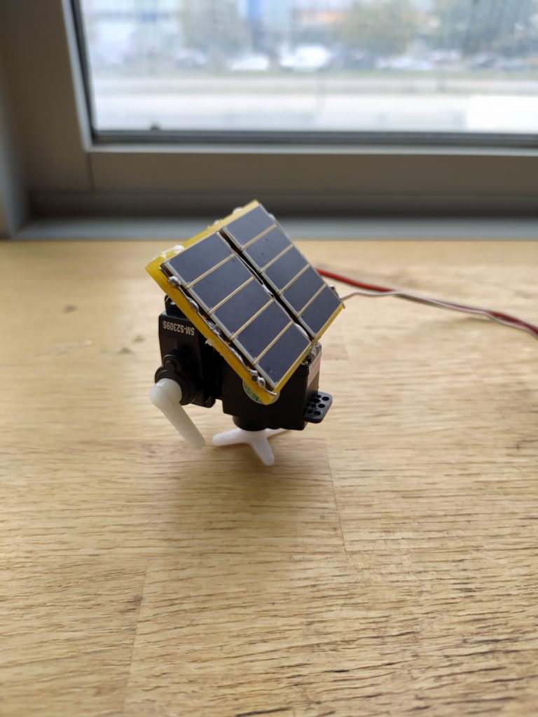
With a makeshift hinge and tilt arm:
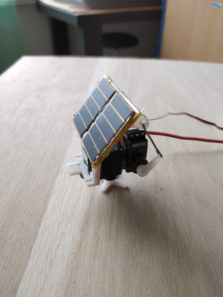
This would only require an Arduino mini pro and some super caps charged by a solar panel through a diode.
Some other more simple options:
For a miniature 2DOF.
A mini 1 DOF.
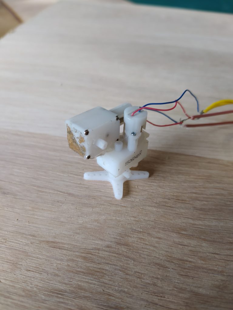
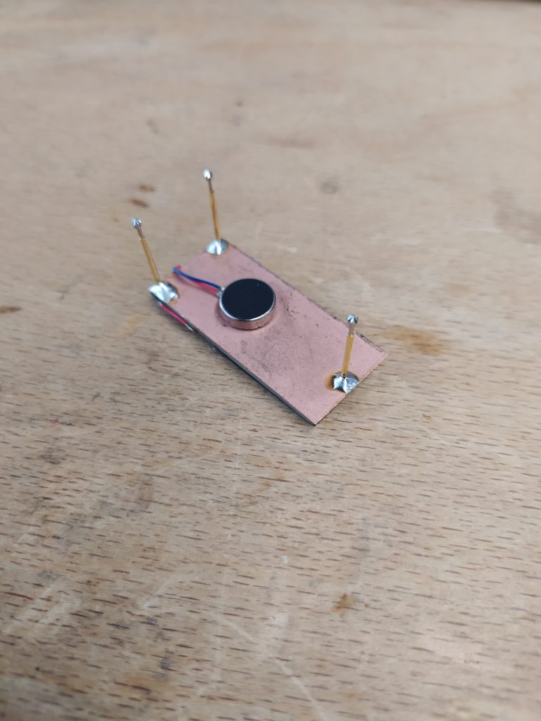
 The 2 metal gear motor design I was working with early on.
*****
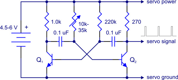
Here is a super simple two servo motor controller that recharges supercaps through a diode:
This works with the code below as a test:
#include <Servo.h>
Servo myservo1; // create servo object to control a servo
Servo myservo2; // create servo object to control a servo
int pos = 0; // variable to store the servo position
int threshold = 100;
void setup()
{
myservo1.attach(5); // attaches the servo on pin 9 to the servo object
myservo2.attach(6); // attaches the servo on pin 9 to the servo object
}
void loop()
{
if (analogRead(A2)-analogRead(A3)>threshold)
{
myservo1.write(90);
delay(15);
}
if (analogRead(A3)-analogRead(A2)>threshold)
{
myservo1.write(-90);
delay(15);
}
if (analogRead(A4)-analogRead(A5)>threshold)
{
myservo2.write(90);
}
if (analogRead(A5)-analogRead(A4)>threshold)
{
myservo2.write(-90);
}
}
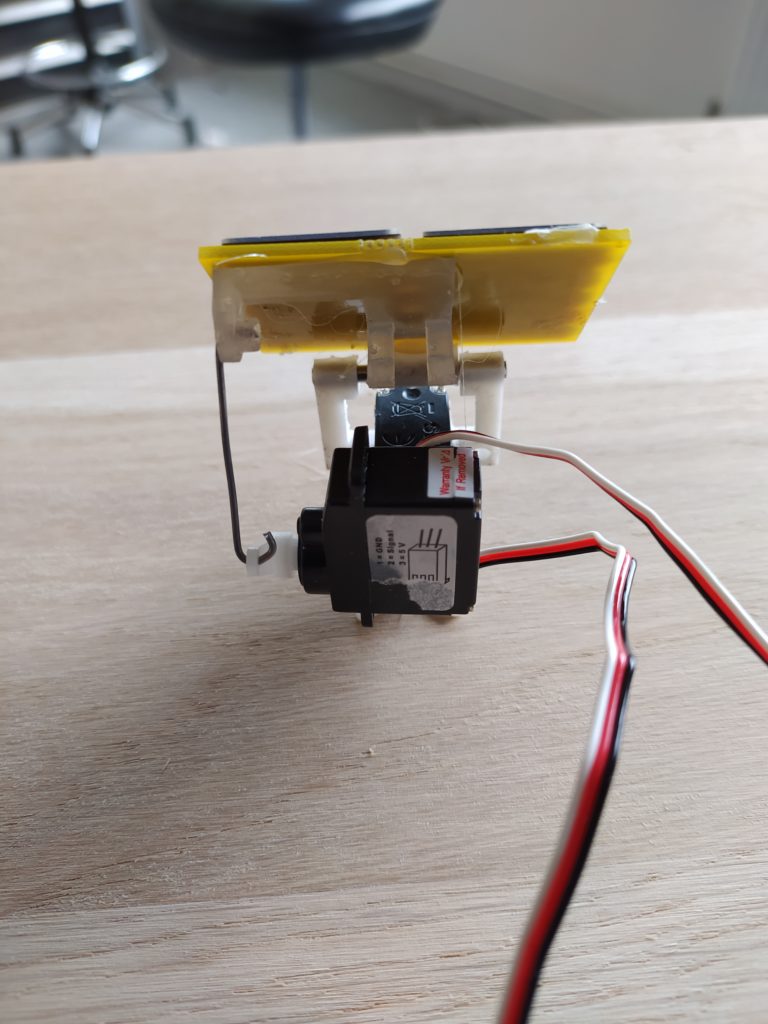
This is the monster in all its tentacularity:
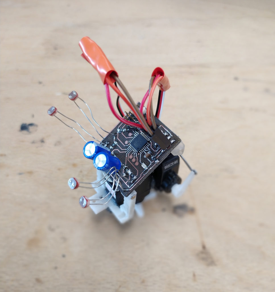
****
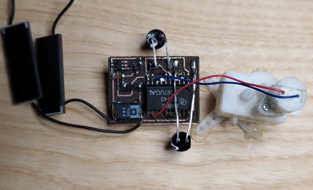
Testing the barebones circuit with the solarbotics white DC gearmotors and the SMD solar engine. It works with only two mini solar cells and the SMD cap as long as the sun is medium strong!
This is exciting as a result (but I just needed the change the motor wire polarity):
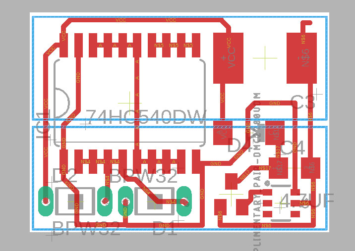
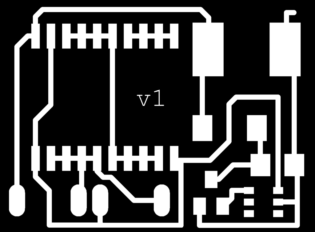
Here’s what the circuit looks like:
This suddenly stopped working and I did the following things:
Checked to see if the cap was charging, if the voltage monitor was triggering (and I manually triggered the MOSFET to see if the motor fired), the voltage at the midpoint between the two photodiodes, and if there were any shorts.
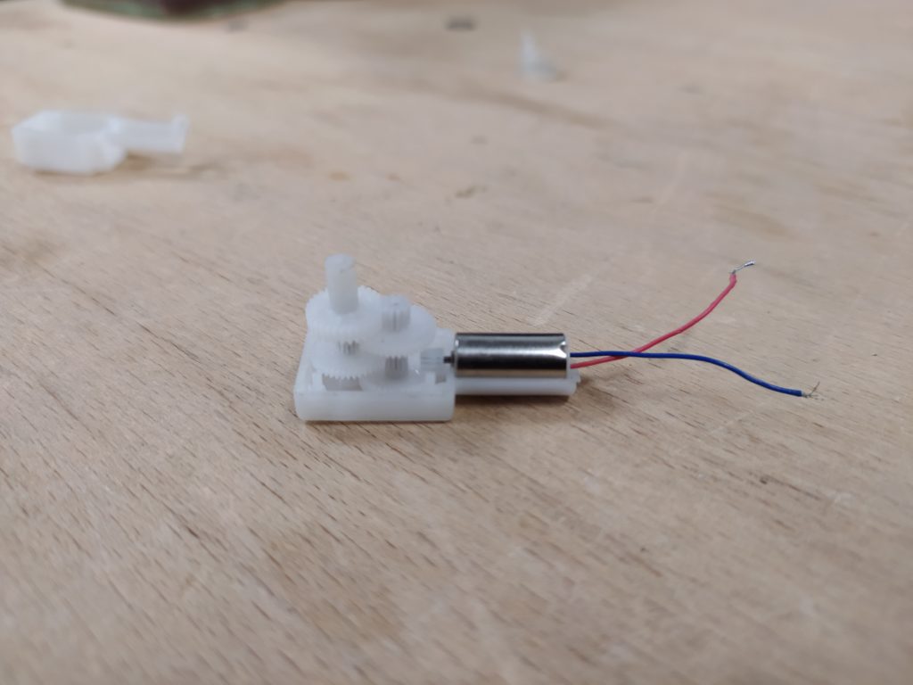
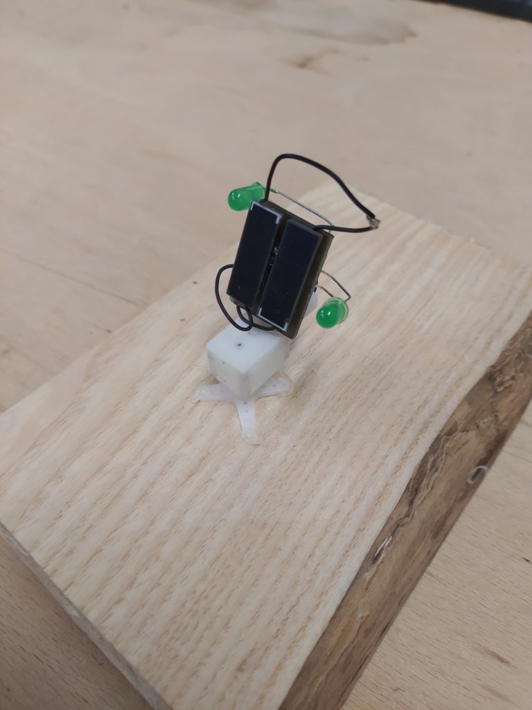
In the end I replaced the zener with a normal SMD diode which I found, replaced the photodiodes with green LEDs because one lead was broken on the photodiode, and then discovered the motor was broken (or at least the blue wire was disconnected on the inside)! It gave me a chance to look inside the tiny gear boxes of the motors though:
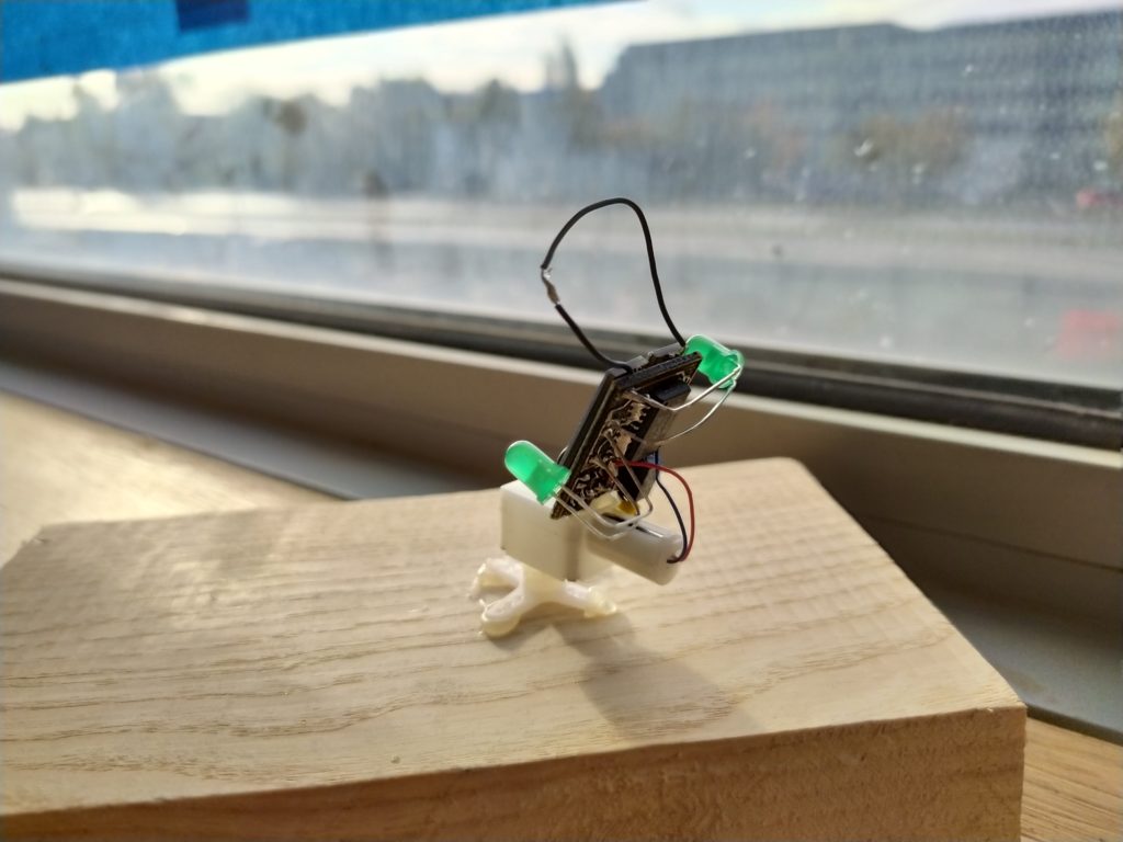
Here is the, once again, working prototype:
I would like to be able to tune the midpoint between the LEDs. I would also like smd light sensors.
Some options for solar panel and motor assemblies:
Here’s with SMD LEDs soldered on:

Not sure why but the thing is only turning clockwise…
I tried the following things:
- A 10K trimpot (with each photodiode into each side of the resistor and the variable pin going to the logic chip). The trim pot at either extreme does indeed make the circuit turn in the opposite direction. However, in the middle it stops either side from firing.
- Replacing the photodiodes with Silicon PIN Photodiode BP34s, green LEDs 5mm, Green SMD LEDS, and LDRs.
- changing the ground of the photodiode pair to the ground of the capacitor instead of the ground connected to the floating connected to the MOSfet.
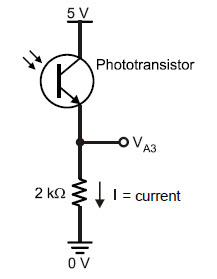
Just found this image here (http://solarbotics.net/library/circuits/bot_popper_240.html) which seems to imply I could use phototransistors also:
Looking at other Smart Head circuits, it looks like the + side of the photodiode pair is connected directly to the Vcc but that the negative side is connected to the “local” ground, not the negative of the capacitor. However, there are also counter examples…
I tried just setting up the dual photodiode circuit on a breadboard. Two photodiodes , two LDRs etc. They each move from a midway value up or down depending on which device is in the dark. However, they don’t always have 1/2V as a midpoint, which appears to be the important threshold point for the oscillator. **EDIT** I think what they meant was half of VCC not 0.5V. I could try to find the exact threshold voltage that is the balance point with the power supply?
2.25V for my desktop breadboard version of the circuit while supplying 4V for the solar panel. 2.85V was the threshold with solar panels at 5V. It also has a dead zone where neither motor will fire if it is perfectly in the middle.
For the soldered version the threshold is around 1.3-1.4V when being fed 4V as solar panel.
At 3.5V solar panel supply, I have a lower threshold bound of 1.25V and a higher bound of 1.4V. In the deadzone neither direction turns.
At 3V funny things happen. It will only turn one direction unless I suddenly make the input 0V. This might explain why my circuit is behaving strangely! I am using a 2.92V voltage supervisor so I don’t think my current circuit is ever going to work.
I should replace it with a higher voltage threshold like this one perhaps: https://www.mouser.fr/ProductDetail/968-ISL88001IH46ZT7A
In the meantime I can use a voltage divider like I did for the 1381.

Here’s the scope output attached to one lead of the motor. The fat, fuzzy part is when the motor is not turning and the threshold is reached. Either side it sends between 1.5-2V to the motor turning one way or the other.
Setting up my own little trim pot between the LDRs I was able to tune them to the correct voltage threshold and everything works well on a breadboard at least.
Here is the 74AC240 datasheet:
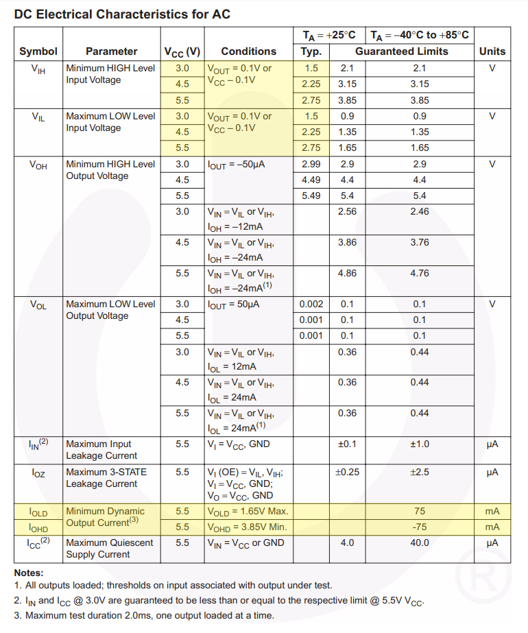
Checked out the 74AC240 datasheet, for 3.5V the threshold should be between 0.9V-2.1V.
****
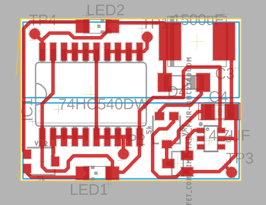
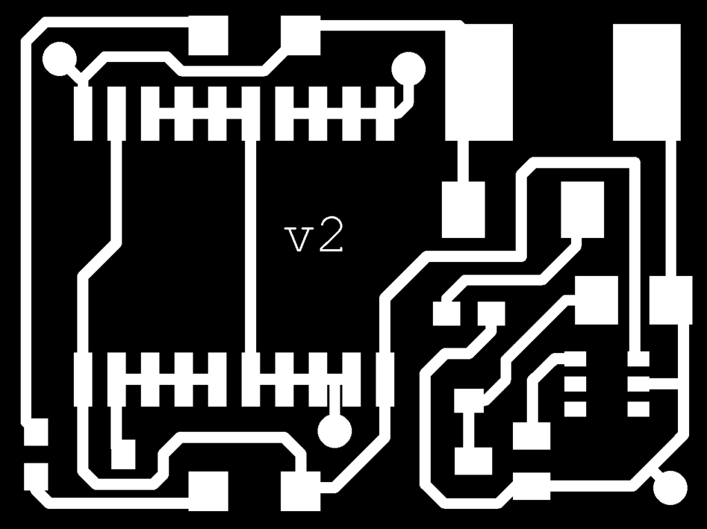
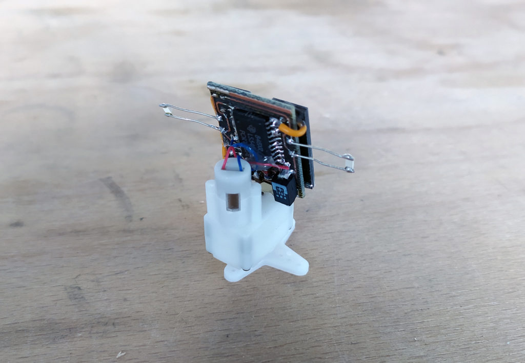
Version 2 of the board has trimpots for the voltage trigger and the light sensors (which are now SMD and on either side of the board):
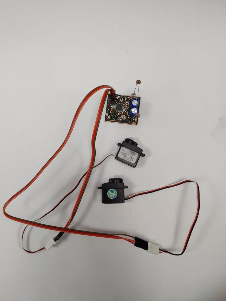
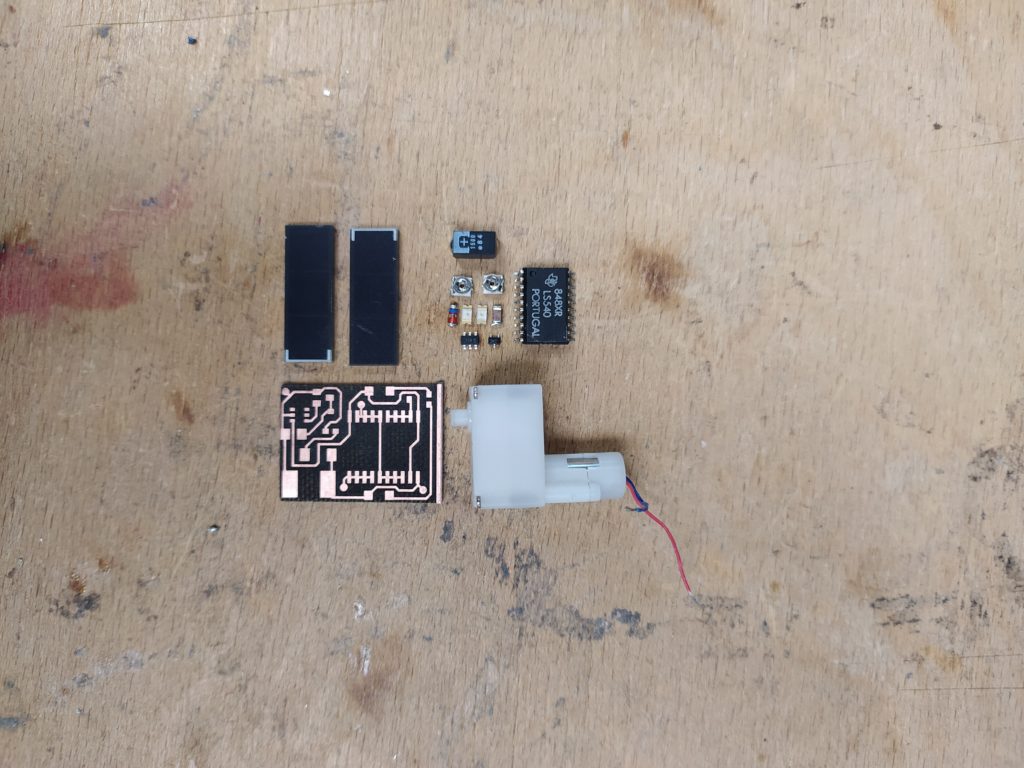
Here are the parts laid out with the new board:
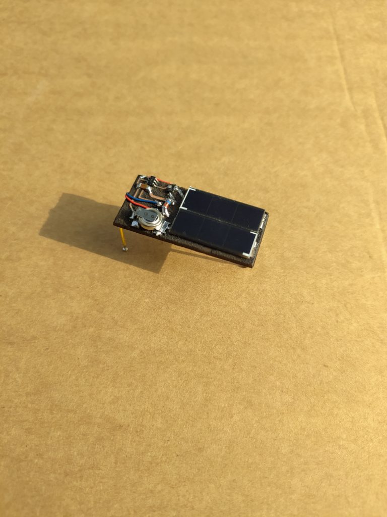
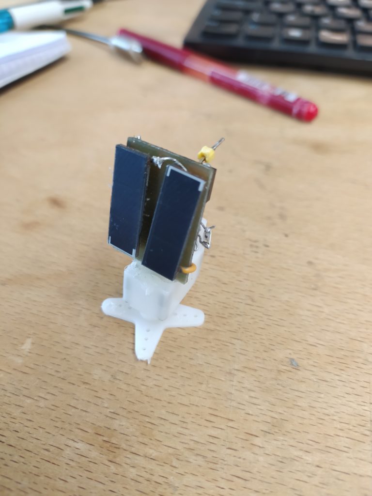
Post-soldering. The size of the board versus two small solar cells:
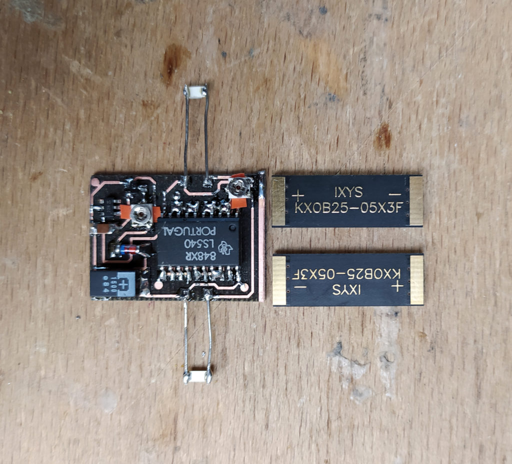
I had to put electric tape under the trim pots because contacts were exposed underneath… The full assembly:
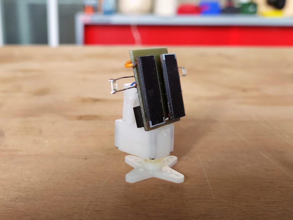

****
Found this online here (http://www.smfr.org/robots/robot_images/dualsolarhead_schematic.png):
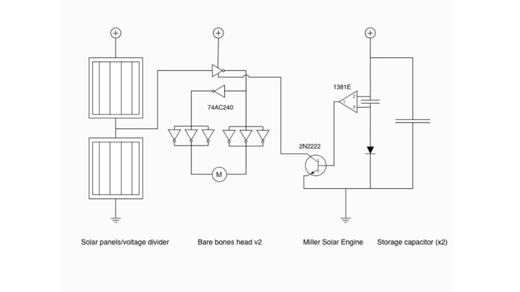
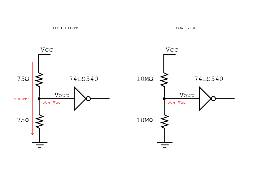
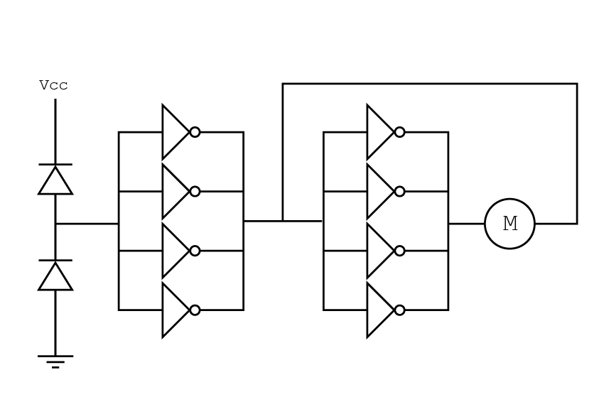
It uses the solar panels as the light sensors! It also lays things out in an easy to understand way (the midpoint is the boundary between what the inverter sees as HIGH or LOW. Once the solar engine has enough power this decision of HIGH vs. LOW then powers the motor through six remaining gates – presumably to increase the current as each pin seems to be limited to 75mA according to the datasheet above?).
***
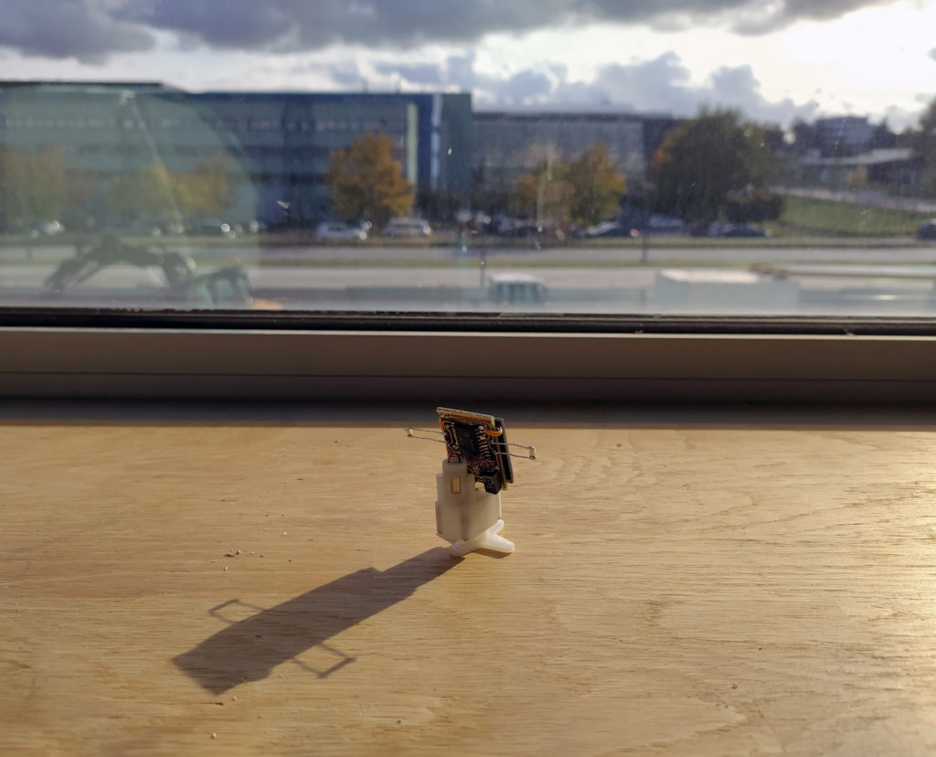
Testing V.2:
I can get 3.5+ volts (4V outside in full sunlight even) with the current setup of two solar cells + little cap!
BUT…When I short the voltage supervisor 5K trim pot the motor fires, but even in its least resistance position the supervisor is not triggering…It is also only doing mini movements, not full shots. I removed the trim pot and now it behaves normally. I don’t understand why the trim pot doesn’t work when it was flawless with the benchtop power supply…
With a 1M trimpot the variable voltage trigger does work just as expected, however! I moved it up to 3.5V ish.
The 5K trim pot for fine tuning the light sensors also does not appear to work. Also doesn’t work with a 1M and two green LEDs…
I tried using the two solar panels as sensors as suggested in the found circuit and it appears to work, there remains the same problem of how to tune the voltage level however if my trim pot solution doesn’t work.
***
I think I need to order 74AC240s (I think the 74LS540s I am using might be slightly different in terms of their HIGH/LOW thresholds) or voltage triggers for 3.5V+. This is a nicely tuned circuit that seems hard to mess with.
Just a reminder of how much the complexity has been reduced in this project!:
***
I have realized I need to understand the circuit I am working with better in order to tinker with it.
First thing, the 74LS540 that I am using has a minimum voltage of 4.5V! It also can only supply 45mA max as an ouput if I understand correctly. However, I also have a 74F244D octal buffer which works as low as 2V. However it is Bipolar and not CMOS technology like the 74AC240 AND more importantly, it has non-inverting outputs. Clearly getting the right logic chip and family is an important element and not a detail for this circuit…
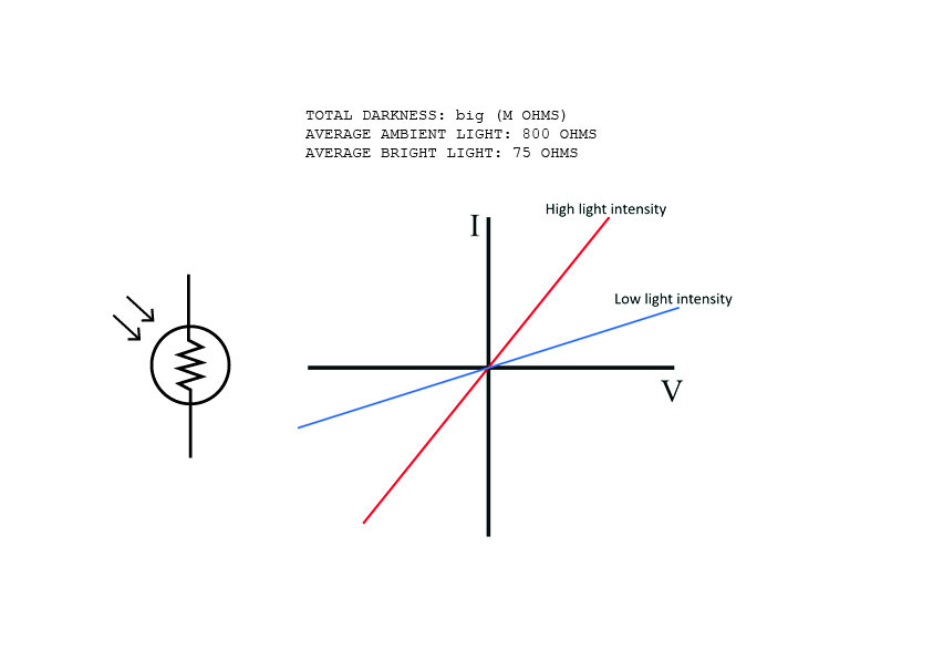
So, the LDR “photo bridge”. After testing 10 we had lying around I arrived at these average values:

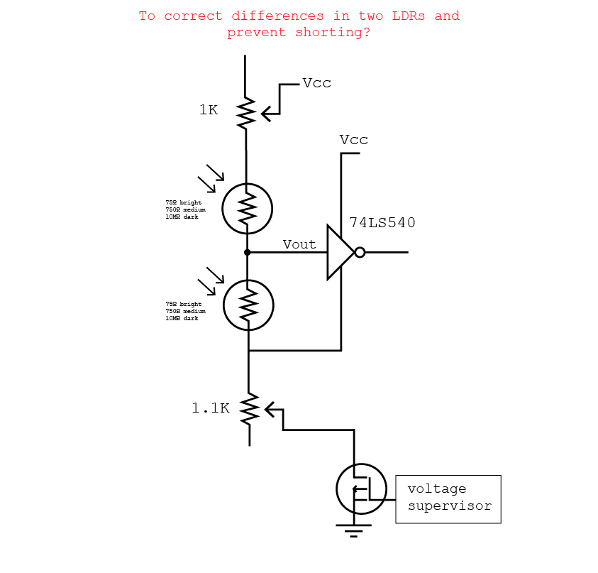
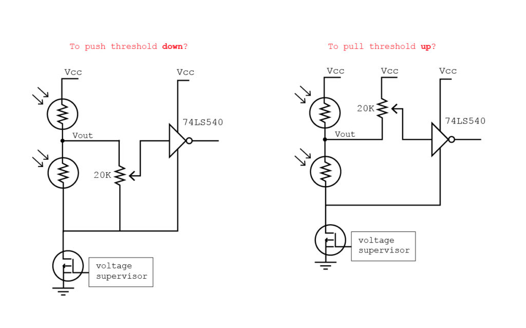
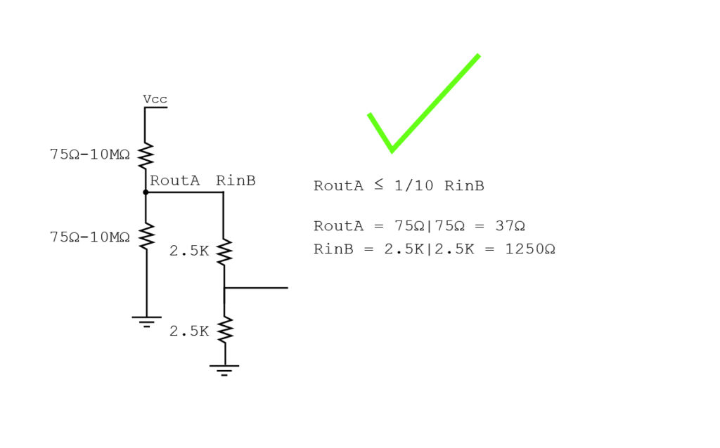
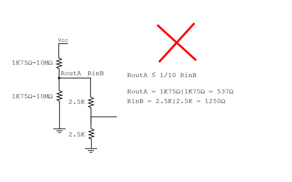
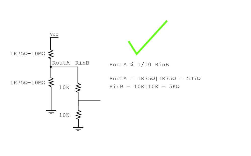
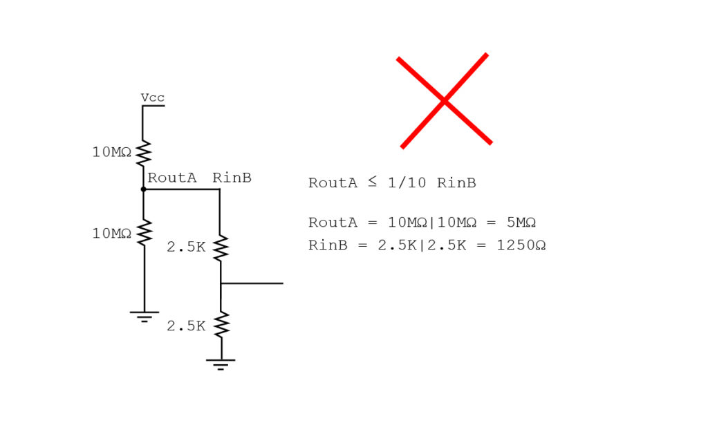
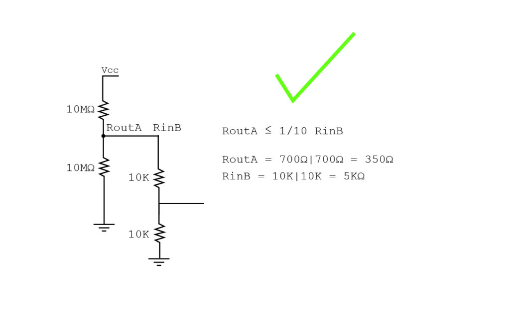
Here’s some R Thevenin calculations (Thanks to Learning the Art of Electronics!) to figure out what size pot I can afford to pull up or push down the midpoint from the LDR divider:
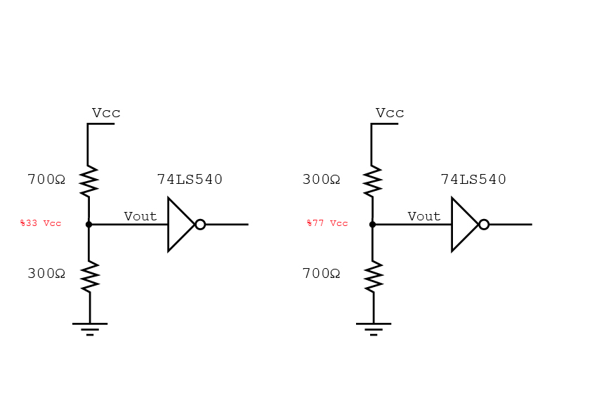
And here’s the current logic circuit in a more understandable format:
****
Did some tests, looks like I need to bring the midpoint DOWN in my circuit:
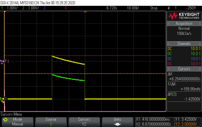
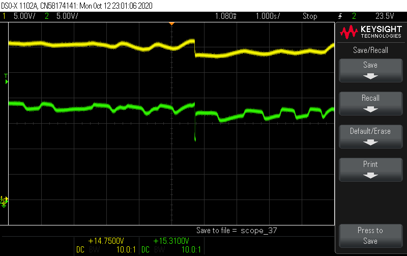
Yellow is the cap voltage (3.42V) and green in the midpoint (2V) with equal light on both phototransistors.
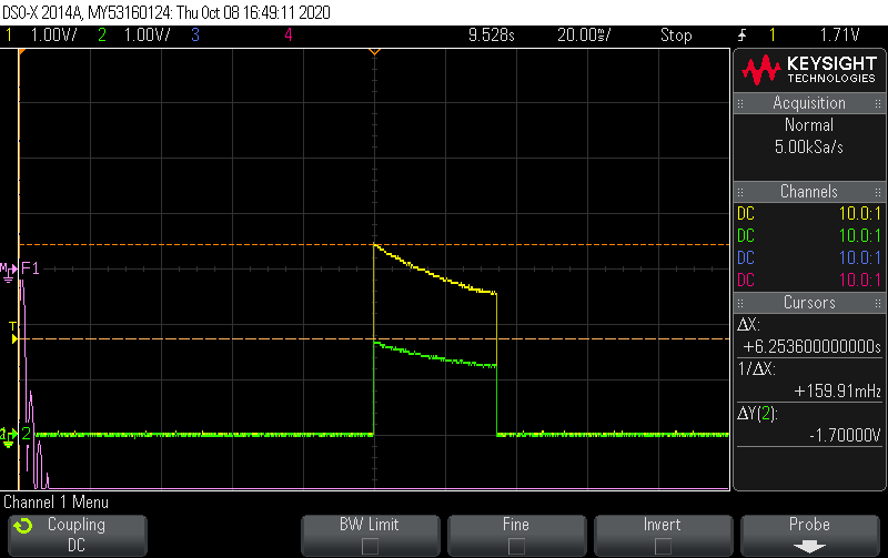
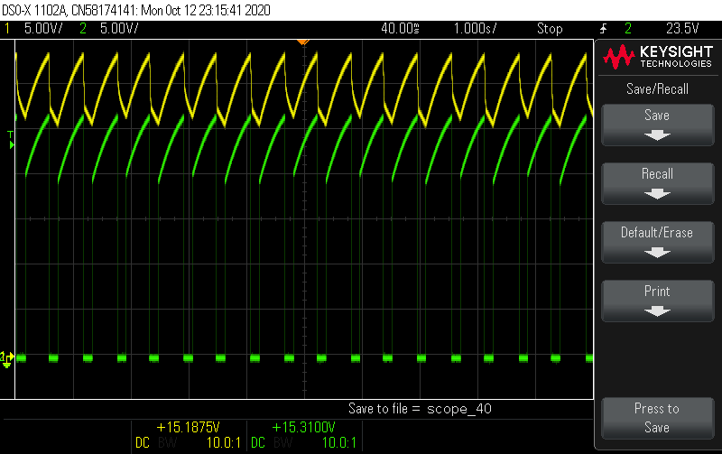
This scope image shows first both photodiodes in light, then the left (connected to GND) in darkness, and finally the right (connected to VCC) in darkness:
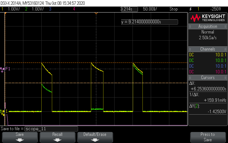
Without even needing to take any measurements it’s evident that the midpoint is too high. This causes the motors to always turn the same direction when the light intensity is equal between the two phototransistors. I flipped the photo transistors and observed the same effect so I think it’s the circuit not the difference between the phototransistors.
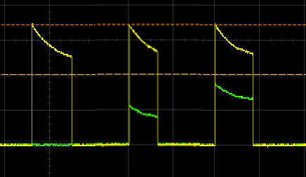
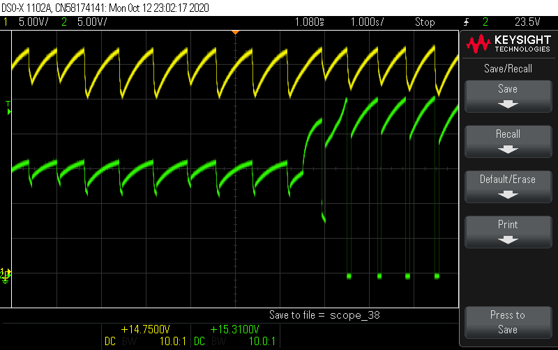
This scope image shows me adjusting the phototransistor trim pot. (Fully attenuating on the left, halfway in the middle and then fully open on the right).
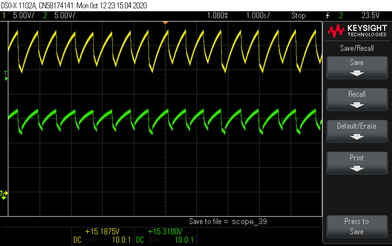
And here’s testing with the middle threshold covering and uncovering each phototransistor:
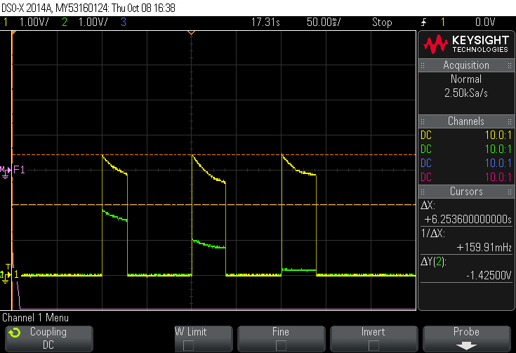
This shows that the 10K trimpot effectively drops the entire midpoint! I can effectively dail in the midpoint to exactly half of VCC now (3.42 Vcap, 1.71V threshold)!:
Now the machine is not turning in only one direction! But it also might need some resistors for when the two photodiodes are both seeing bring light. I also need to replace the LS540 with an AC240 because I am currently operating outside the maximum minimum voltage of the IC. It would also be nice to use the solar panel as a sensor and thereby reduce the part count (I could still tune the midpoint in the same way once I determine which way the imbalance is – it would also solve the shorting problem in high light).
I varied the pot and everything is working as expected. I also added heat shrink to the phototransistors. Here is a video:
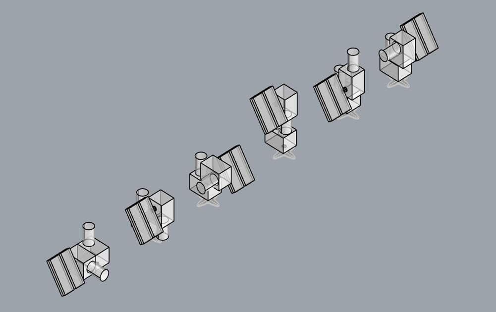
I tried some 2DOF designs but I think this needs to stay MINIMAL and the force of the project, if it comes, will come from the array more than individual complexity. Plus they already seem imbalanced and more likely to malfunction…
Some tests with the solar panel voltage divider:
Here’s what it looks like when I change the solar panel midpoint with the 10K trimpot:
Here is the solar panel midpoint trim pot all the way to one side:
Here is the solar panel midpoint trim pot all the way to the other side (not sure why it goes all the way to the ground here only):
Here is me putting one panel in the shade, then the other. The difference is not massive.
The problem is that now I fall into a large deadzone where no movement happens in the middle. I’m trying to find the right combination of voltage trigger trim level and solar midpoint level but it’s not easy without sunshine…
****
Here’s the cost per unit of this design:
74AC240: 0,462 €
0.2F cap: 1,21 €
solar cell: 3.56 € (1.78 € x 2)
micro gear motor: 4.25€
voltage trigger: 0,356 €
diode + 0.47uF cap: 0,1€
PCB: ?
Total: 9.938€ + PCB cost
****
I have now a 1M trimpot on the solar midpoint and have added a 1M between the midpoint and VCC to try to balance things out.
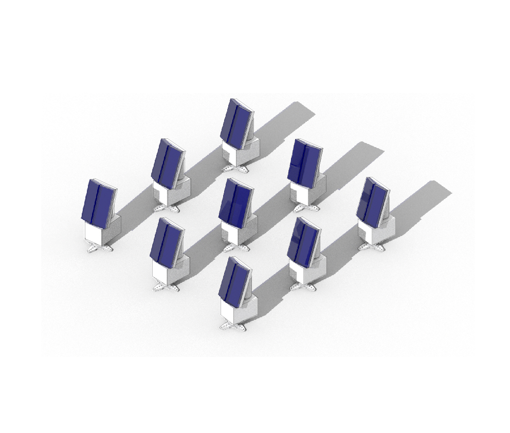
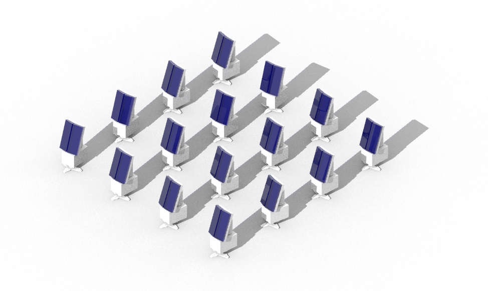
I think 3×3 is better than 4×4 ? 5×5 would be out of control.

****
Working towards simplifying the dual servo sun seeker. Here is a post for controlling servos without a microcontroller:
https://www.pololu.com/blog/18/simple-hardware-approach-to-controlling-a-servo
Could use LDR pair to replace pots inside the servos, based on ideas from Hackaday post shared with me by Paolo Salvagione:
***
Went back to the super simple business card sun shaker and added some feet. I also tested the new 0.2F caps and they work with outdoor light but might be too tough to charge with indoor light (unless it’s actually bright then they work fine). After Paolo Salvagione’s comment about using a smaller motor to rotate the device, it occured to me that I could use the vibe motors in two directions to create movement that follows the sun:

****
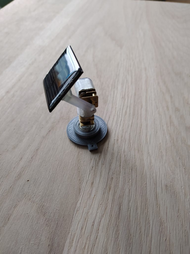
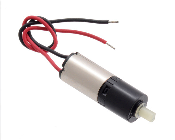
Ordered this motor:
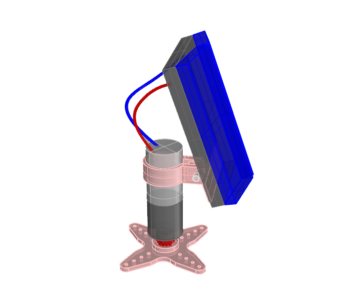
Here is a new design with (human) adjustable tilt. It has more of a “pro” vibe. The motor adds 5 euros to the total cost of the machine bringing it up to 15 euros:
****
Looks like the trick with the light sensing is just to put the photodiodes behind the board so that the shadow cast by the sun creates a clear preference for one side or the other. They can be bent around a little bit to be perfectly tuned but it also adds a bit of idiosyncracy to the ‘bot. So it doesn’t appear that I need a trim pot for this option. I’m not sure how to create the same contrast with the solar panels as putting either in the shade is obviously not a good idea. Pointing them in different directions creates some difference but not a great deal.
****
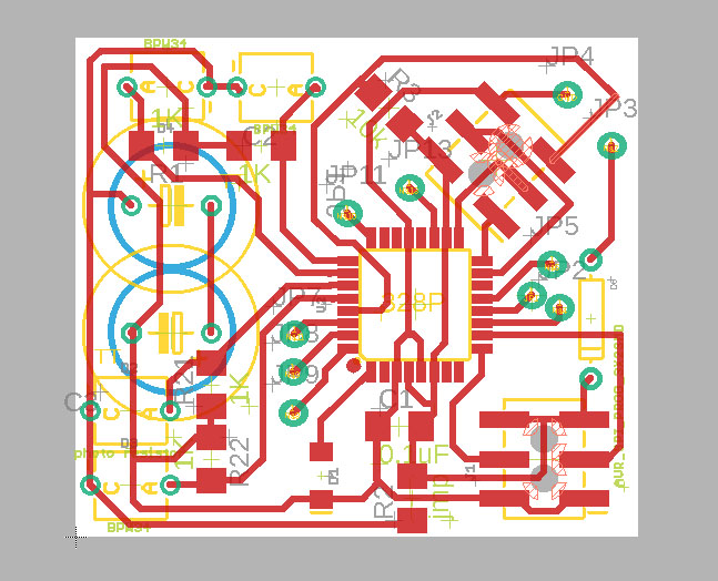
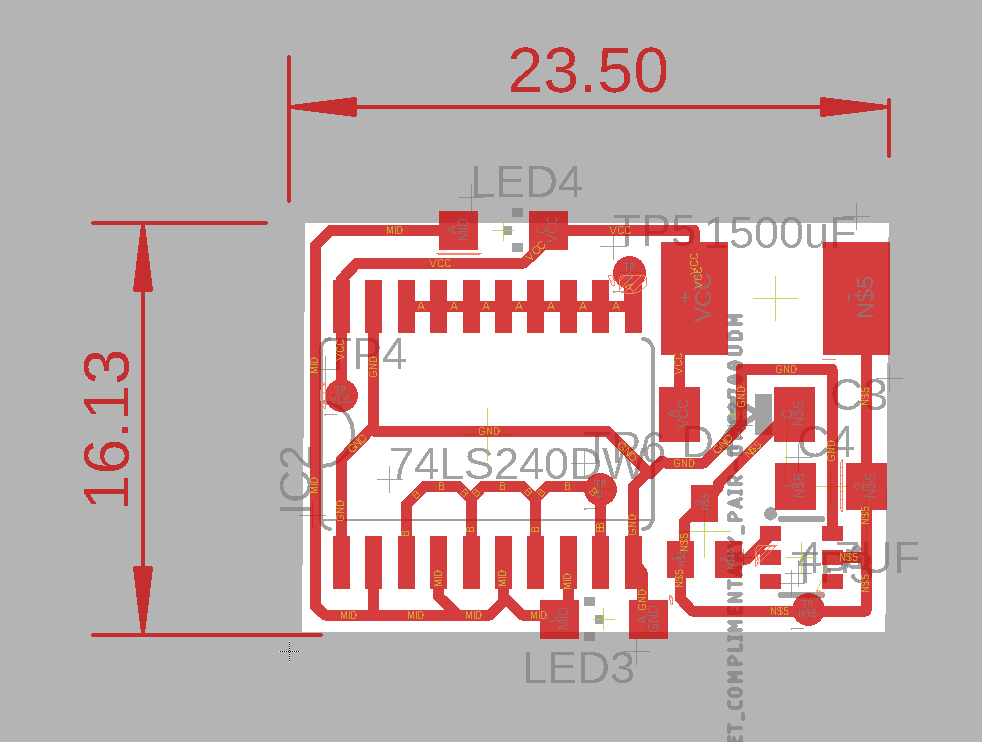
I’ve redone the circuit for the 74AC240 and make it more compact:
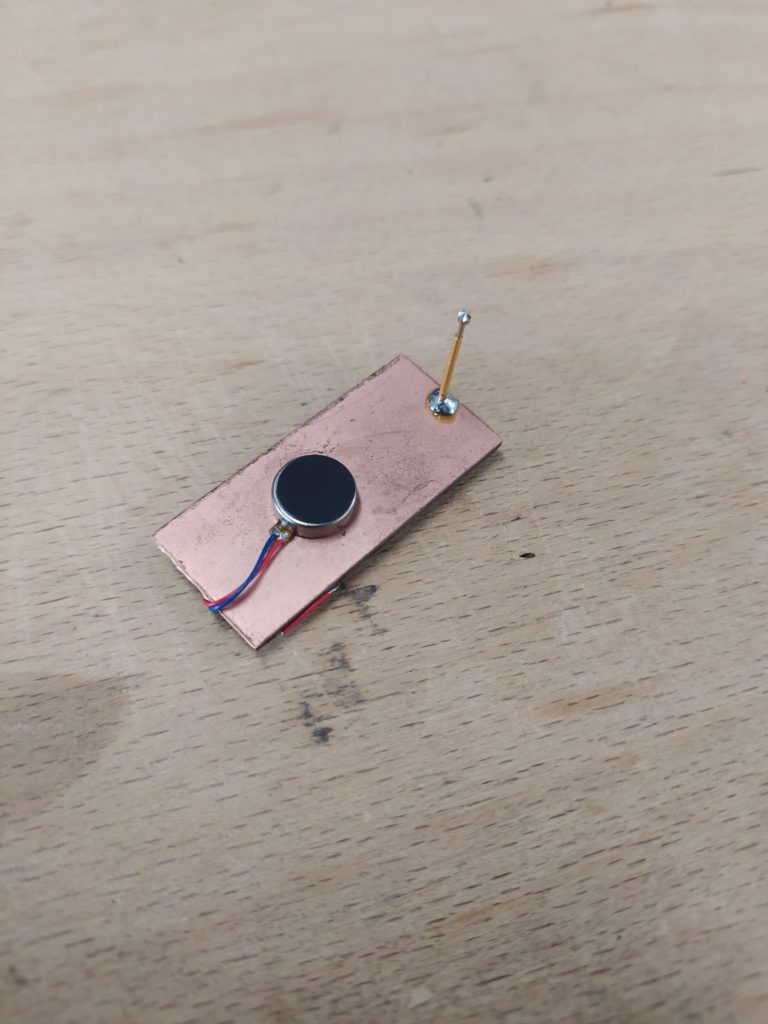
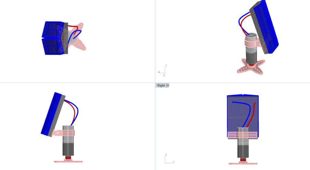
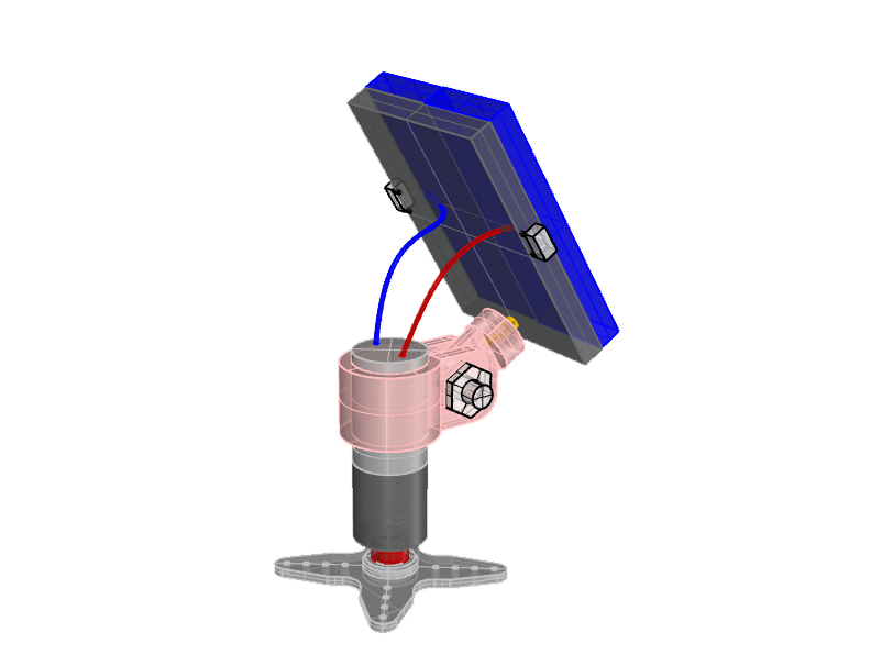
Here is my next design with the smaller DC gear motor. I’m imagining a soldering a pin to the PBC in order to attach the pivoting arm to it. Otherwise the issue is how to make this attachment without creating a whole frame and bumping into components etc. It has a small M2 bolt to fix the print to the motor and to adjust the angle:
I’ve made a cleaner video of the first prototype: