Making things easier, simpler, more plug and play.
****
WorkshopOrganize partsPalimpsest.OSGet all channels workingGet raspberry pi VGA out workingTest with raspberry pi VGA putFix VGA input/output (I know what the problem is at least :)! SPI SRAMGet recording as fast as possibleTry with 4MB FRAM ?New board with several + raspberry pi + snake-like channel overwriting?FPGATry simple VGA with LatticIce40Solder FPGA board
So many cables and wires and machines….something more minimal / smaller and portable possible ?
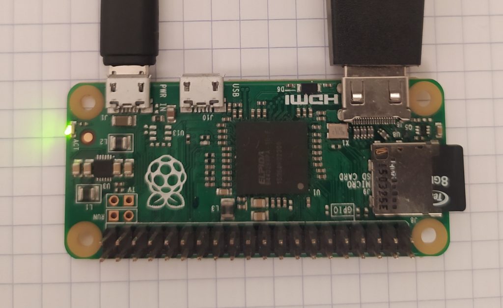
I’ve got a Raspberry Pi Zero outputting VGA nicely. On startup it launches VLC in fullscreen and plays a playlist of iconic film excerpts. I activated hotplugging so it keeps looping even if the adapter is unplugged for long periods of time.
I used Win32DiskImager and downloaded the ISO Image Raspberry Pi OS with desktop (around 1GB) from the officiql website (https://www.raspberrypi.com/software/operating-systems/) and put it onto an 8GB SD Card.
In terms of connectors I needed a SD Micro > SD card adapter, HDMI mini > HDMI, an HDMI > VGA, a USB A > USB Micro for power, and a USB Micro to USB A female in order to plug in a mouse / keyboard.
I followed these three tutorials for setting up VLC autoplay and turning off annoying VLC text:
https://forums.raspberrypi.com/viewtopic.php?t=17051
Raspberry Pi: Run VLC on startup and play slideshow videos/pictures from folder
https://www.shellhacks.com/raspberry-pi-force-hdmi-hotplug/
Now adding a power off button (not good to pull the plug while running)
https://howchoo.com/g/mwnlytk3zmm/how-to-add-a-power-button-to-your-raspberry-pi
**EDIT The rasbpi turns off when I unplug HDMI or plug into the palimpsestOS. Is it because RGB are mixed with only 100ohm resistors ? Should I have 3 blocking caps and then mix after ?
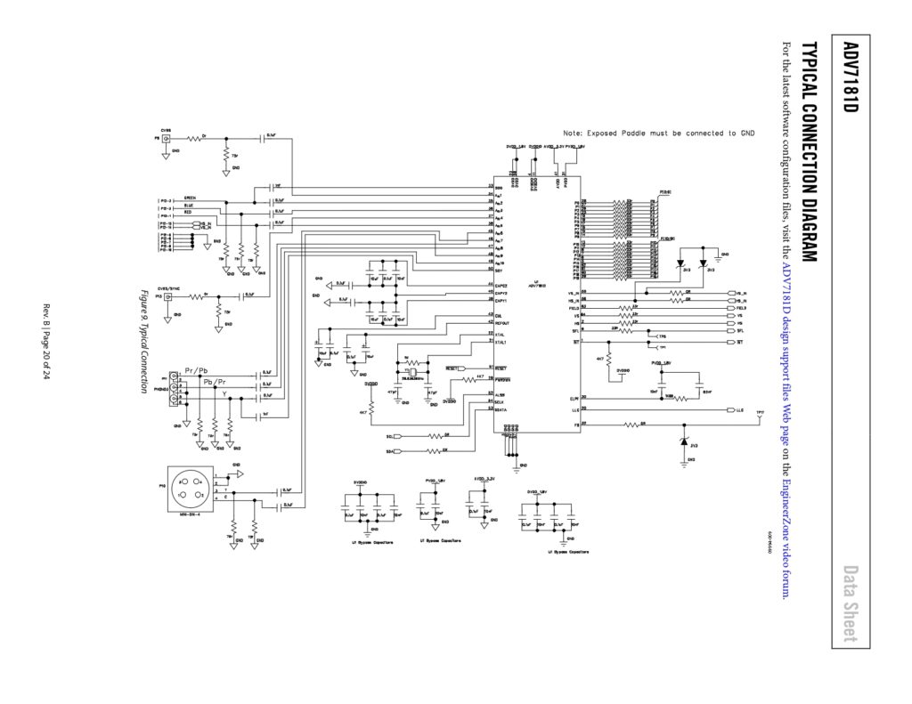
Here’s a write up on how to VGA :
https://chipnetics.com/tutorials/understanding-75-ohm-video-signals/
Looks like parallel 75ohm resistors going to GND from the input is good practice + a cap and 75 ohm resistor on output?
VGA OUTPUT examples :
![]()


If I understand this last one, three parallel 75ohm resistors makes a 25ohm resistor. 97ohms gets 80% of 3.3V gone before the 25ohm dissipates the rest so that there is 0.7V left for the 3 channels. For a 5V supply like mine, I’ll need to remove 86% of 5V to get it down to 0.7V. A 160 ohm resistor then ?
VGA INPUT examples :
![]()
*EDIT Made the changes (RGB colors in to GND through 75ohm, one color through cap to bias + 160ohm and now there is no output…But maybe it was already broken at this point? Can test when new converters arrive.)
Looked at some VGA in/out boards I had in my possession and saw the following :
- H and V sync can go to a 74HC125 Line Driver / Buffer.
- Color returns can be conected together and grounded along with chassis.
- Examples of color pins going to grounded 75ohm resistors then on to blocking caps. Also colors to gates of transistors.
- Colors also going to video signal switcher like this : QS4A210 – 2-Channel 4:1 Analog Mux/Demux
- Definitely DO NOT ground pin 9 (which is 5V), as I have done in all previous boards…
****
An older HDMI to VGA converter broke so I opened it up to see if I could reproduce it. It’s an ALGOLTEK AG6201 which appears to be not accessible anywhere but the manufacturer’s website.

The alternative is using a video chip which can trasmit HDMI like this project : https://hackaday.com/2019/07/26/hdmi-from-your-arduino/ which uses a CH7035B HDMI encoder.
Alternatively I use the HDMI to VGA adapter and solder a D Sub Standard Male connector (https://www.mouser.fr/ProductDetail/TE-Connectivity-AMP/2301843-1?qs=rrS6PyfT74crws9wAQVNoA%3D%3D&mgh=1&vip=1&gclid=Cj0KCQjw27mhBhC9ARIsAIFsETE7Rp9JFGXhYFAXh_Z2YbQUB2NfHqO8rM7yPueb-T3yFiKbUMvJkOEaAtjJEALw_wcB) to the board.
***
I will be testing a pico projector and a VGA capture device soon…


***
Trying again with SPI SRAM
This code seems solid to me but I can’t go beyond 100Hz…
#include <SPI.h>
#include <SRAM_23LC.h>

// SPI bus can be SPI, SPI1 (if present), etc.
#define SPI_PERIPHERAL    SPI
#define CHIP_SELECT_PIN   8

/* Device can be:
 * 128KB: SRAM_23LCV1024, SRAM_23LC1024, SRAM_23A1024
 * 64KB: SRAM_23LCV512, SRAM_23LC512, SRAM_23A512
 * 32KB: SRAM_23A256, SRAM_23K256
 * 8KB: SRAM_23A640, SRAM_23K640
 */
SRAM_23LC SRAM(&SPI_PERIPHERAL, CHIP_SELECT_PIN, SRAM_23LCV1024);

// Additional SRAM chips
// SRAM_23LC SRAM1(&SPI_PERIPHERAL1, CHIP_SELECT_PIN1, SRAM_23LC512);

#define START_ADDRESS   0

//uint8_t buffer[BUFFER_SIZE];
//#define BUFFER_SIZE  320

char buffer[1000];
#define BUFFER_SIZE  (sizeof(buffer) / sizeof(uint8_t))

void setup(void)
{
  pinMode(2, OUTPUT);
  /* Without parameters, begin() uses the default speed for this
   * library (12MHz for samd, 14MHz for sam, and 4MHz for avr).
   * Note that SPI transaction support is required.
   */
  SRAM.begin();
 // SRAM.begin(8000000UL);      // or specify speed
  //Serial.begin(9600);
}

void loop(void)
{
  //while (!Serial); // Wait for serial monitor to connect

// Record a series of values
  for (size_t i=0; i < BUFFER_SIZE; i++) {
    //buffer[i] = byte(digitalRead(A2));
        if ( (PINC & (1 << PINC2)) == (1 << PINC2) ) { //PC2 is what we're reading
        buffer[i] = 0xFF;// pin is high
        }
        else {
        buffer[i] = 0x00;// pin is low
        }
  }
/*
  // Print buffer to serial monitor
  Serial.print("Write Block: ");
  for (size_t i=0; i < BUFFER_SIZE; i++) {
    Serial.print(buffer[i], DEC);
  }
  Serial.println();
  */

  // Write block
  if (!SRAM.writeBlock(START_ADDRESS, BUFFER_SIZE, buffer)) {
    //Serial.println("Write Block Failure");
  }

  // Clear buffer
  //memset(&buffer[0], 0, BUFFER_SIZE);

  // Read block
  //Serial.print("Read Block:  ");
  if (!SRAM.readBlock(START_ADDRESS, BUFFER_SIZE, buffer)) {
    //Serial.println("Read Block Failure");
  }

  // Print buffer to serial monitor
  for (size_t i=0; i < BUFFER_SIZE; i++) {
    //Serial.print(buffer[i], DEC);
   if(buffer[i] == 0x00){
     //digitalWrite(2, LOW);
      PORTD &= ~(1 << PD2);    // set pin 2 of Port D low
   }
   else{
    // digitalWrite(2, HIGH);
      PORTD |= (1 << PD2);     // set pin 2 of Port D high
   }
  }
  //Serial.println();
  //delay(1000);
}
I just can’t manage to get the same level of control with an SPI device as with parallel SRAM and counters.
****
New board time 😀 ! Test new things but keep the plug and play idea from last board and make even more so. SPEND MORE TIME SANITY CHECKING THE DESIGN and double checking pull ups and downs.
Goals :
- How about using a 16Mbit SRAM to store 128MBits of data with only a few added components ?! The plan is a pair of shift registers to convert serial output from a comparator into 8 bits to be sent all at once to the SRAM and the inverse on the output side. I would need the shift register clocks to be 8 times faster than the SRAM I think?
- Make it so power (5V – with an LDO on board to eliminate possibility for accidents) can be shared with a double power jack. Reverse polarity protection.
- A fine and coarse threshold selection !
- proper VGA input and output good practices that will never harm anything sending video signals in or recieving signals sent out (blocking caps, 75 ohm impedence matching, Vref for top side of variable comparator bias!!, buffers for H and V sync!!, two cables close together!! and shielding – guard rings? – on the PCB for these traces!! different grounds for different parts of the VGA cable, use BNC connectors for RGB??)
- Raspberry pi as input VGA through converter which plugs into a male VGA on the board, add an OFF/ON switch to safely turn off
- pass thru VGA signal switch !!
- Have different clock cans to switch between?
- Extended Display Identification Data chip as a test?
- Have audio out option ?
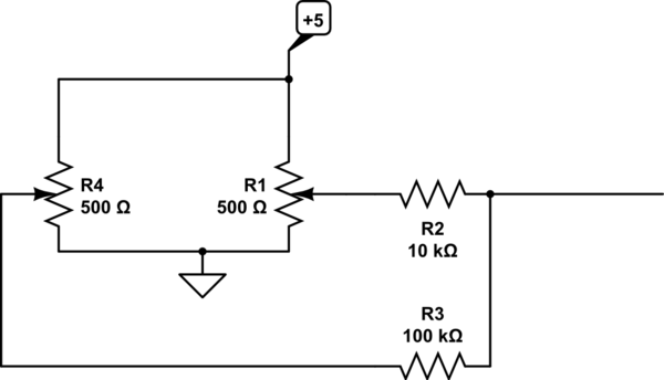
Here’s the preliminary circuit :
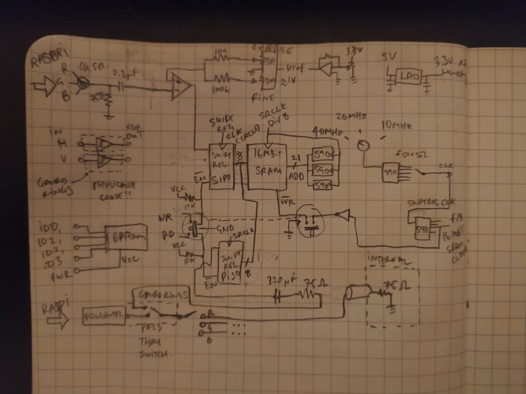
From https://www.cs.unca.edu/~bruce/Fall11/255/Labs/Lab13AnalogInput.html
From https://electronics.stackexchange.com/questions/144530/circuit-for-a-coarse-and-fine-setting-potentiometer
****
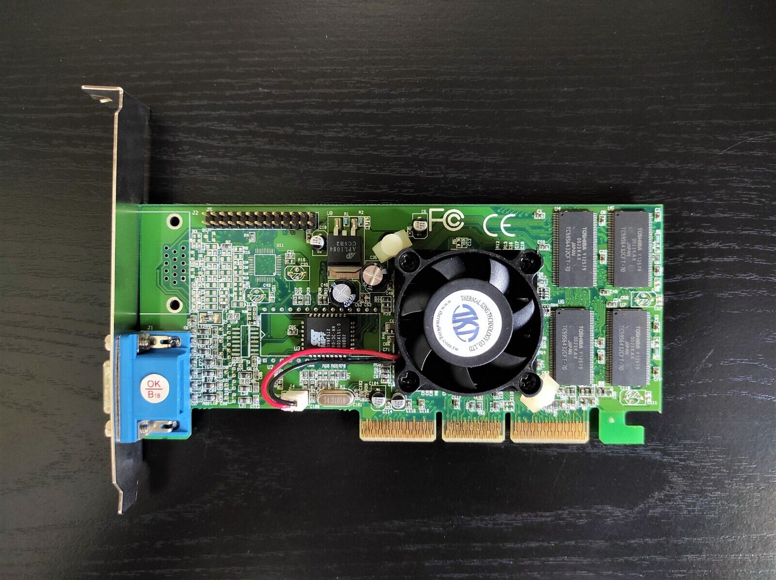
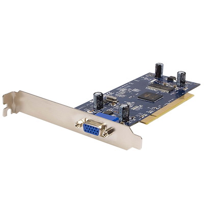
As for PCB inspiration, perhaps something that evokes the computer video graphics card :
Rectangular, with metal bracket (these are called Computer brackets in the Circuit Board Hardware – PCB category of Mouser.fr. They come in low profile or high profile), fan, heatsink, memory bank in a row, name of the board somewhere, PCI connector

****
Here is my first attempt at simulating the logic :
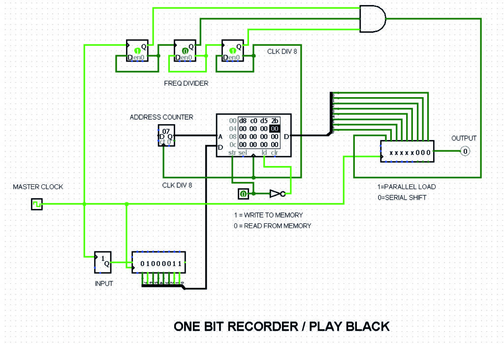
The only tricky part was activating parallel load of the output register only once per 8 clock cylces.
This design includes a giant FPGA to control enables all broken out along the PCI-E connector (that could be played like a piano with an alligator going to GND) in time and also to match the aesthetic of the video card. It would feature a stunning 128 Mbits (16MBits SRAM x 8) of memory. Would be cool to have LEDs next to each memory which light up when that block is recording.
***
Building on the idea of making physical artefacts, Vivien Roussel had the idea of moving towards displaying the chassis of the computer along with these boards. There are loads of cool test bench computer cases that could be an inspiration for this :
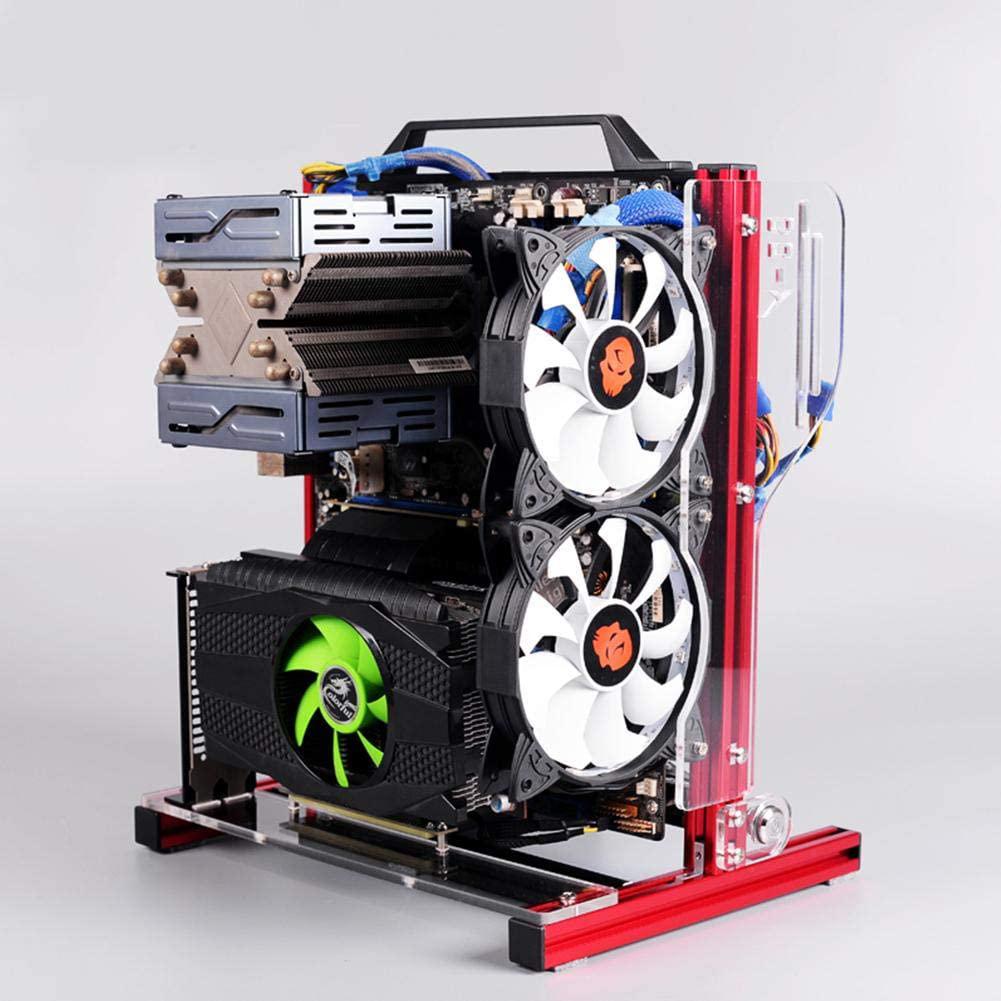
****
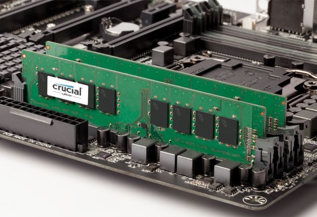
Or a DDR SDRAM module as inspiration :
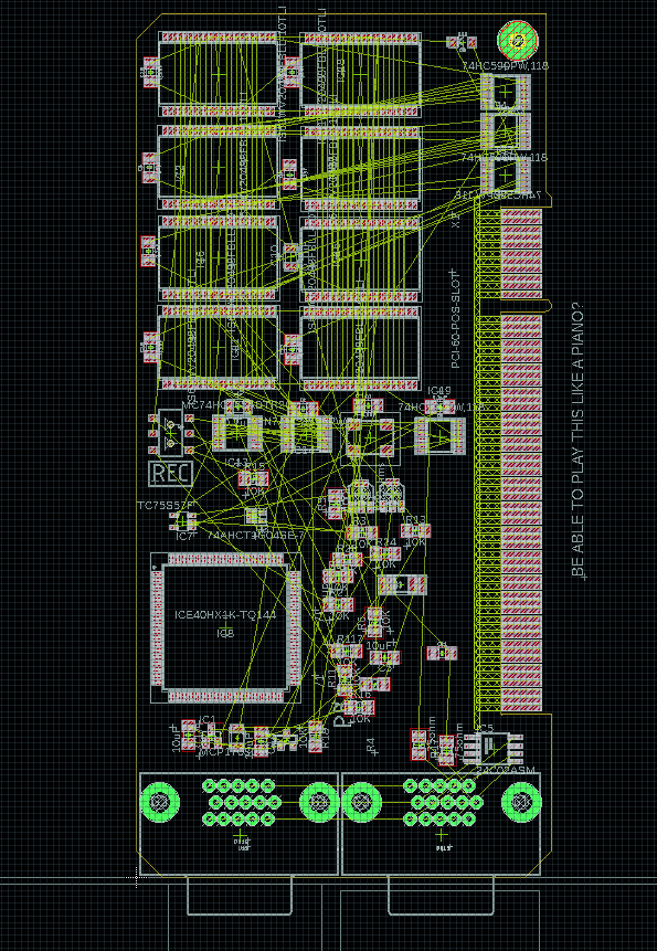
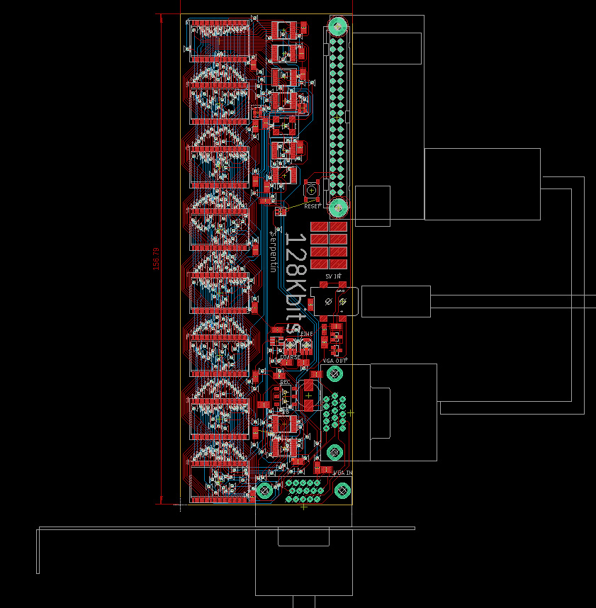
Here’s what it’s looking like in Eagle so far :
I still like the idea of a kind of piano controlling :
- 3x SRAM CS sel bits
- 3x COUNTER EN + individual RST
And of course :
- Threshold control (fine and coarse this time !)
- Clock DIV
- REC/PB
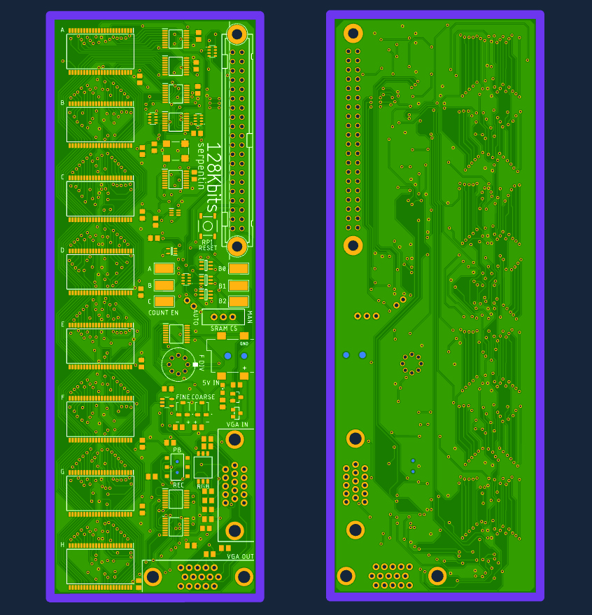
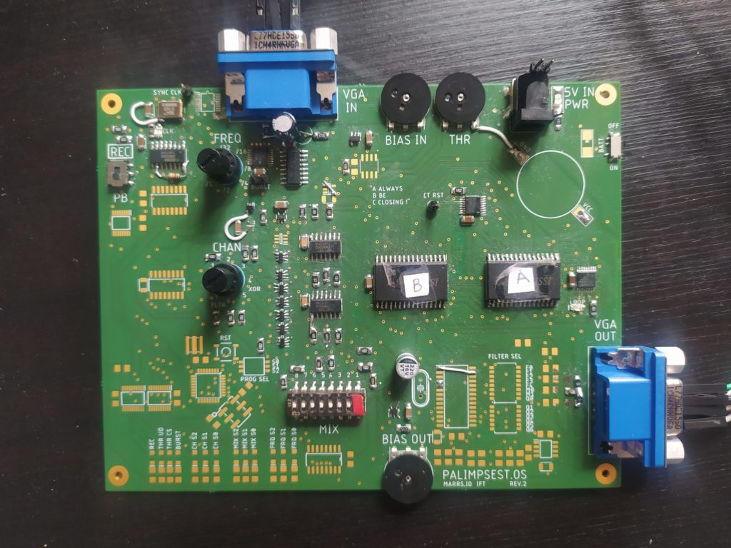
Here’s the board as ordered :
CIRCUIT DIARY :
- The fine and coarse pots appear to work very well.
- The clock divider works as expected. Though it might be interesting to be able to play with different frequencies too as it seems to be important to get the combination of sampling versus pixel frequencies.
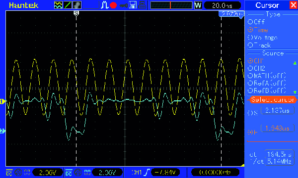
- I checked and the serial clock is indeed being divided by 8 and inverted (albeit super noisy!) :
- The Overflow and CS signals appear to be working well (though I had a hard time soldering the resistor networks!)
- The !WR signal is as expected
- Possibly should have put pull-downs for the SRAM I/0 pins ?
- I should have made a timing diagram not just the simulation..
- The option to manually advance the OVERFLOW signals is cool because you can solder one SRAM and test only it without having to wait for its turn to come around !
- I have reached a problem : the 596 is not shifting the serial into parallel. I can see it trying (little mini signals getting through), but it is as if the I/O pins are being pulled low, but by what ? The SRAM ? I’ve confirmed we’re in write mode so they should be high Z. The Serial to Parallel converter somehow? But the I/O pins are inputs for this IC…Hmmm. Is it something to do with the open drain outputs (or the Schmitt trigger inputs?) on the 596 ? **EDIT : Had a 595 with the same footprint and substituted it, seems to be working now.
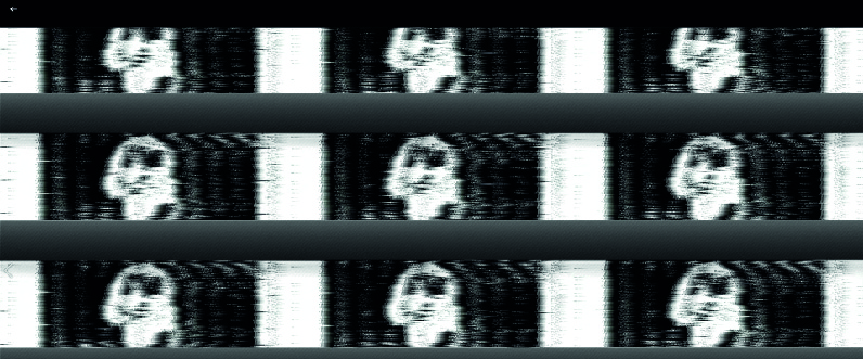
- So, the output is very stripey. I have removed the 75ohm resistor to ground and shorted the 100ohm to the output RGB pins. I’ve tried shorting the blocking cap and it makes things a tiny bit easier to see but overall it is barely legible as an image. I think it has something to do with the output parallel to serial conversion. Here is a sample of a capture :

- For some reason it can also work much better :
- I don’t understand how it is possible to see the screen while it is recording as there is no “pass-thru” option…. There is also sometimes quite a difference from what is somehow passing through while in record mode and what plays during PB mode. *EDIT*There is a noise issue, when the VGA input is plugged in there is static that is entering somewhere. Trying to locate it currently. *EDIT* it is coming from the VGA IN. Tried connecting a bunch of GNDs (digital GND, chassis GND, color return RED) but still getting nowhere trying to eliminate the noise.
- I ordered the wrong type of bracket, this one is for a double row VGA…
- I had an issue with SRAM D but then replaced it and all is good.
- I forgot to have a pre-amp before the comparator, this is essential otherwise you don’t get any in screen peaks and basically don’t see anything unless you’re really lucky. I used the Palimpsest.OS preamp and bias setup and it works fine.
- The tiny trimpots need to be replaced with actual knobs !!
- I forgot to add loop LEDs ! It would have also been cool to know which SRAM is currently recording.
- EVERYTHING IS WORKING I CAN’T BELIEVE IT. The solution was to just test everything with a simple ramp using the function generator and look at the play back. Then I checked the pins on the SRAM and saw funky signals for several address pins that looked like they were several signals being added together. Clearly when I soldered in a bunch more SRAM and there were tiny connections between five different address pins and an I/O that I did not notice. This was causing chaos. I found the connections and fixed them, now it’s recording just as expected and it’s so glorious. NOTES : I am using the op amp from Palimpsest.OS AND crucially, am connecting both Analog and Digital Grounds between the two boards and the VGA IN with VGA OUT.
***
While waiting for this board to arrive :
- Try different function generated patterns of hitting count 0 enable while recording on the 16Mbit version
- Test the 8 layer board ! *DONE*
- Remove pin 9 GND and fix other issues with VGA in and OUT with VGA beakout PCB
- Test on raspberry pi / computer IN *DONE*
- Test feedback ! *DONE*
- Try mini projector *DONE*
- Try VGA capture device *DONE*
- Put restart button on rasbpi
*******************
*EDIT* It works with rasbpi when I connect only a color, GND, H and V syncs !! So much more convenient than previously.
- It might be cool to be able vary the mixing of the different channels
- The output image is quite faintweak, I think I should rexamine the resistors I put at the termination and maybe switch to B+W.
- It’s a bit muddy with several channels, would be cool to be able to filter that
- I need a path to feedback with a pot !
- Switched the output resistors to a 150ohm going to R,G,B and it works nicely.
- Dip switch hard to use without tool.
- Hard to see which direction switches are pointing in darker light
More technical ERRATA :
- Pin 1 of the 40MHz clock should be pulled HIGH to be enabled, not LOW as it is on the board !
- The THRESHOLD pot isn’t connected to GND on one side…
- I should have tied the CCLR (pin 10, which resets when pulled LOW) of the 590 to VCC with a 10K instead of leaving it floating connected to VSYNC. This made it malfunction.
- BIG PROBLEM : I ordered multiplexers (unidirectional) instead of analog switches (bidirectional) ! The ‘157 multiplexers mess with SRAM B’s I/Os when it is in READ mode (when the SRAM is outputing values on the I/O pins). I ordered a replacement that is pin compatible, the 74LVC1G3157 (DATASHEET : https://www.ti.com/lit/ds/symlink/sn74lvc1g3157.pdf?HQS=dis-mous-null-mousermode-dsf-pf-null-wwe&ts=1679316452048&ref_url=https%253A%252F%252Fwww.mouser.de%252F). EDIT* The new components work perfectly – everything is good !
- The Sync Clock IC is 3.3V not 5V…
- Image jumps around of course. When I try to record with the Burst AND IC which outputs !CLK, no writing can occur. I’m guessing this gate messes with the timing somehow? As a workaround I’m trying to connect the 4 AND’ed V SYNC counts to either the address counter IC Reset or to another reset somewhere.
- Lots of noise on V SYNC, I should maybe have made the input and output VGA jacks right next to one another…
- Pin 9 of the VGA D-SUB 15 is VCC for the Display ID EEPROM chip – but I have it connected to GND !! In general I need to respect the rules around the different grounds and return pins in the VGA protocol and not just connect them all together. Hoping to fix this in the next version.
***
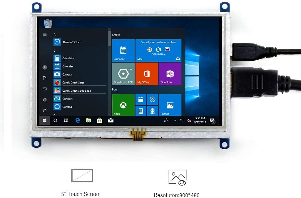
Thinking about making a board with a small 5″ screen / or a mini projector incorperated in it
Fabien suggests using an LCD driver from a normal sized computer screen for a smaller screen (but he says it will will in 16:9 format). The other option he suggests is to use an FPGA to control a screen directly with LVDS.
Artist Andreas Gysin’s LCD 1 from http://lcd.ertdfgcvb.xyz/
***
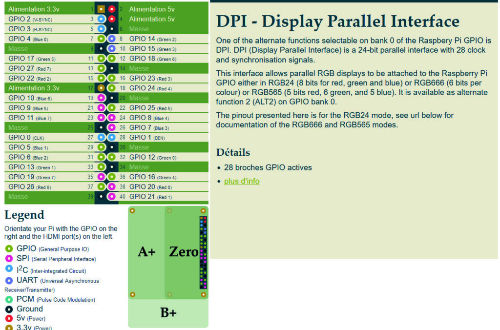
Just realized that I could have an raspberry pi using VGA directly from I/0 pins : https://fr.pinout.xyz/pinout/dpi#
****
Currently thinking the next PCB should be raspberry pi sending video through I/O (not through HDMI) and FPGA controlling SRAM. This would allow messing with the sequence of the memory recording / playback. Could make a compact version of this project (a kind of black box, deployable version) without many external components but with sililar functionality. I could test making the FPGA USB programmable board too. Of course it would also be programmable.
To get here :
- make the automated palimpsest.OS board
- make the simple FPGA VGA board
****
I am revisiting the SPI SRAM code with renewed patience, I actually wrote it first on paper !
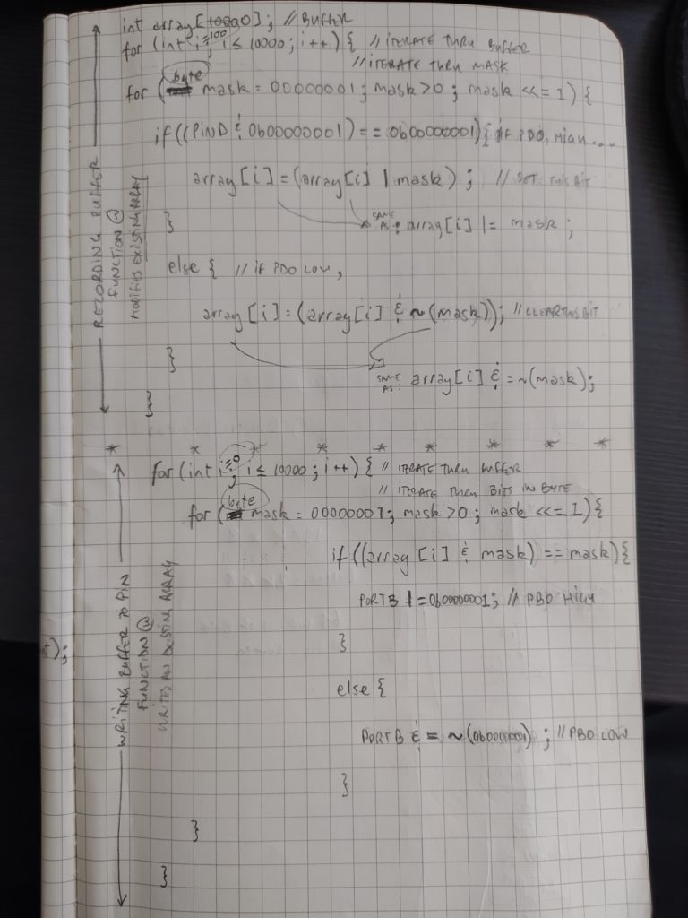
Here is my simple buffer filling code first off :
const int buffer_size = 2000;  // Only 2K bytes of SRAM on the 328P
byte buffer[buffer_size];
void setup() {
  DDRC = 0b00000000;  // set PC2 as input pin
  DDRD = 0b00000100;  // set PD2 as output pin
}

void loop() {

  //  fill the buffer
  for (int i = 0; i < buffer_size; i++) {  // iterate through buffer
    for (byte mask = 0b00000001; mask > 0; mask <<= 1) {  // iterate through a bitmask
      if ((PINC & 0b0000100) == 0b00000100) {  // if input pin high...
        buffer[i] = (buffer[i] | mask);  // set this bit
      }
      else {
        buffer[i] = (buffer[i] & ~(mask));  // clear this bit
      }
    }
  }
  // read buffer back
  for (int i = 0; i < buffer_size; i++) {  // iterate through buffer
    for (byte mask = 0b00000001; mask > 0; mask <<= 1) {  // iterate through mask
      if ((buffer[i] & mask) == mask) {  // if bit in buffer is high...
        PORTD |= 0b00000100;  // ...write output pin high
      }
      else {
        PORTD &= ~(0b00000100);  // else, write output pin low
      }
    }
  }
}
Tried to see what this produce on the screen. I’m using a comparator from the previous board to do ADC and then feeding the ouput through a 470ohm resistor to red. It just leaves little comets which don’t appear to relate to the image…
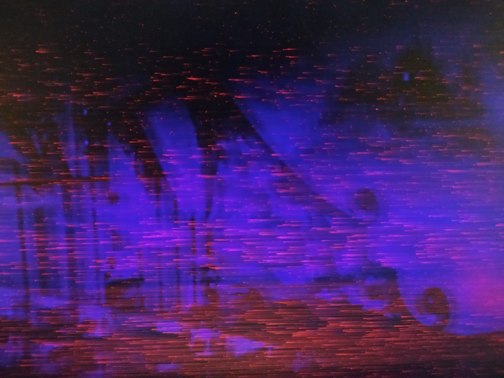
On the scope it doesn’t look far away though :
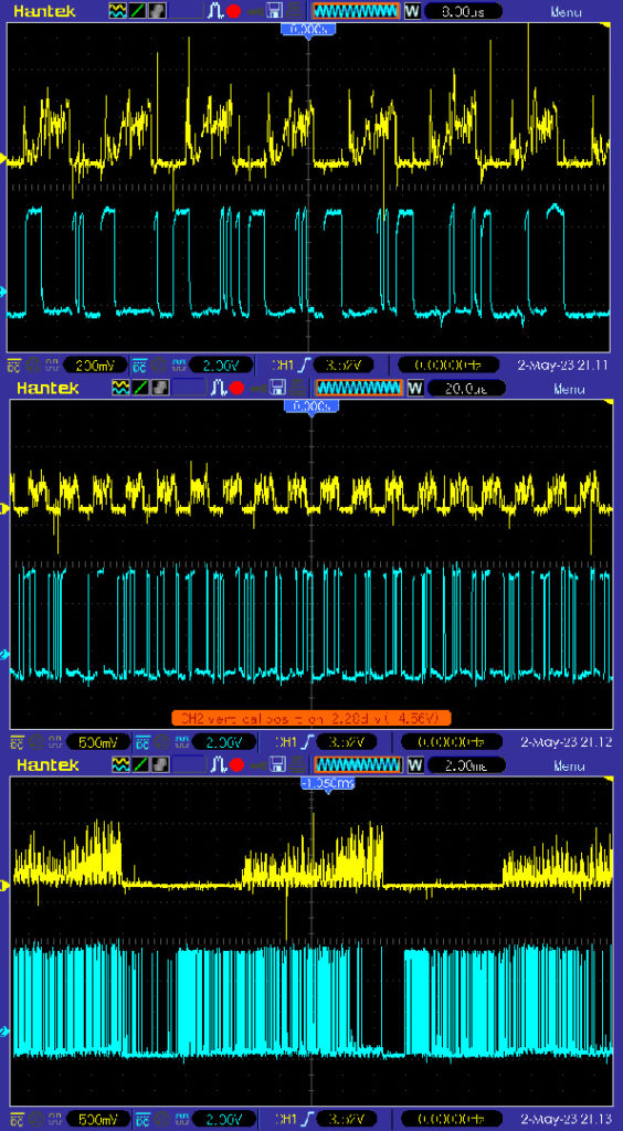
Hmm…
****************
After skimming from Nand2Tetris and checking out the VTECH Video Painter, I realized I could make a really basic screen interface :
- I could record an image and then have an algorithm go through it and make changes (like photoshop effects like blur or polarize).
- I could have sprites stored and then copy them into the screen-memory mapped SRAM
- I could even have a joystick move from pixel to pixel and let you draw, copy and paste and draw circles !
- It could also be a non uniform mapping from memory to the screen !
****************
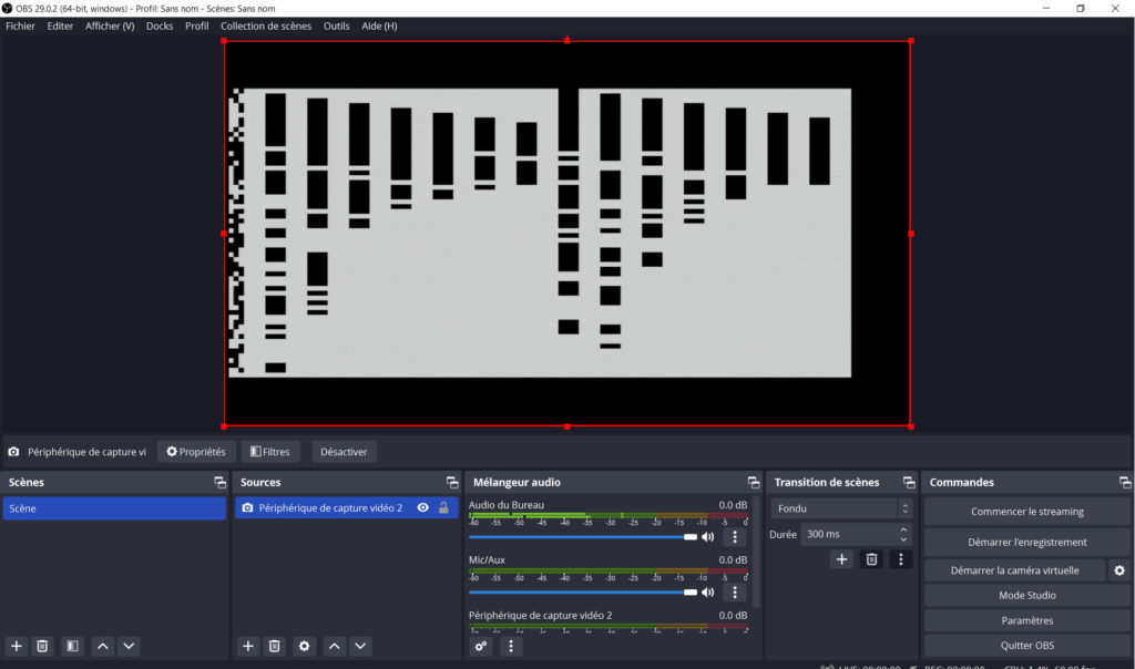
The VGA Capture is working and it’s fantastic ! I’m using OBS, I just clicked ADD SOURCE and then Video Capture device. It needs to be plugged in to USB A, not C, for the LED to come on.
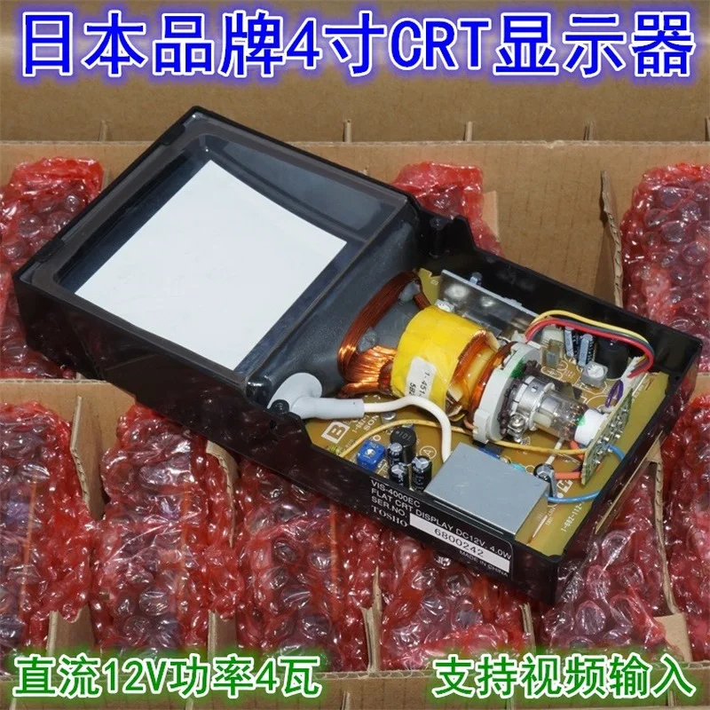
I tried the mini projector but it didn’t like the signals I was sending it. I think I have to avoid intelligent interfaces that can decide to send or not along my signals. Wondering about the camcorder CRT viewfinder and if I should head back in that direction.
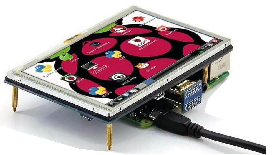
Here is a popular 4″ screen :