Continuing the project of making a small solar tracking device.
****
Idea to simplify the circuit drastically and make the 3D model a bit more robust and less fragile so it is far easier to assemble and won’t topple over (while hopefully maintaining some elegance…)
-Battery-powered (and possibly solar recharging through very simple circuit):
plus Attiny with two steppers only powered directly from output pins (max 40mA and danger of kick back which might be solved with diodes) and no light sensing – just the almanac algorithm for sun following. *
*(Remember you can test the stepper resistances to know which are pairs!)
Tried powering a stepper directly with an Atmega using the Stepper library in Arduino with a bunch of different step and speed values – if it turns at all it’s extremely weak…So this doesn’t appear to be an option.
Tried powering an atmega328 directly to cap and solar panel through diode, in medium sun there is no action. With bright sunlight it manages to power up despite blinking a blue LED every secon. I could try with the sleep timer I recently acquired (https://www.adafruit.com/product/3573). Or maybe a simple sleep code will be enough. This seems like a viable option which would simplify the circuit considerably.
Another cheap and simple option is the ULN2003, but this requires 5V to function unlike the low power DRV8833 I have.
***
Tried driving the stepper gearmotor chain drive and it moves very smoothly and almost imperceptably.
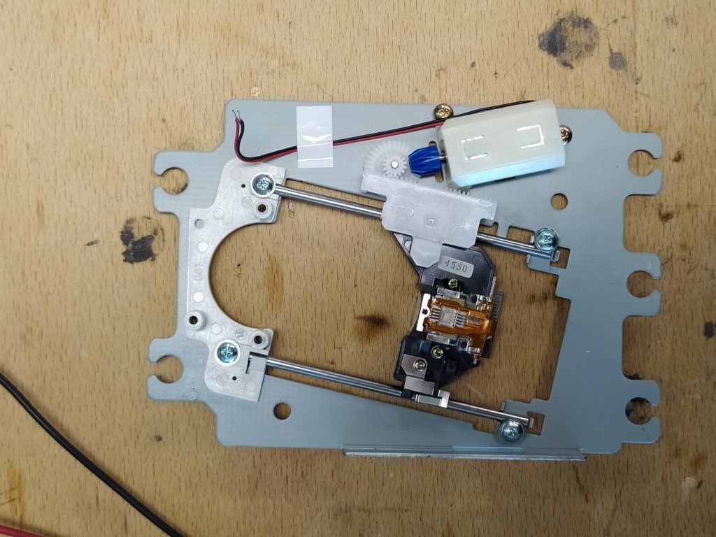
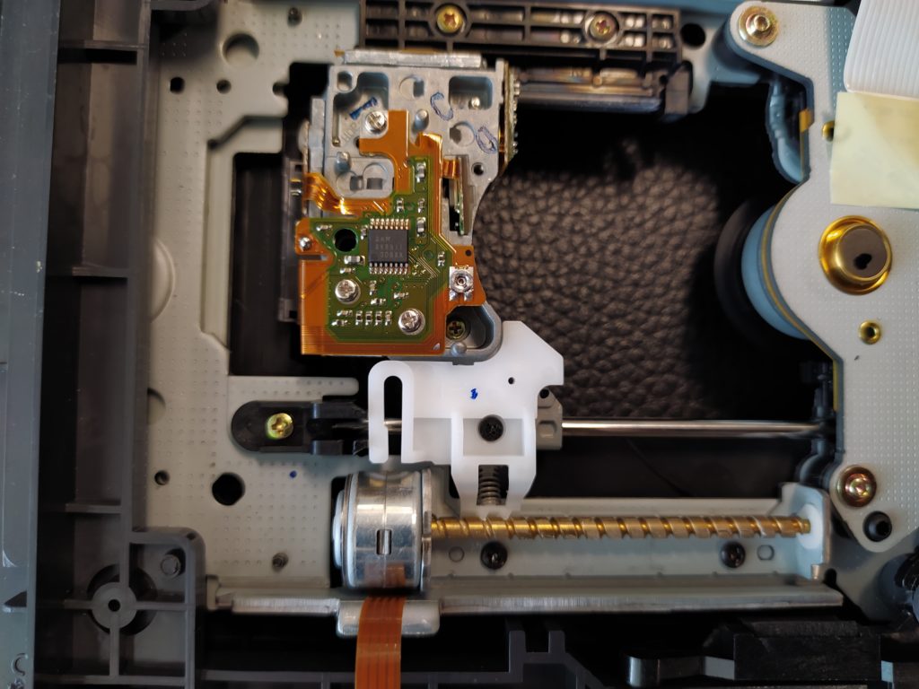
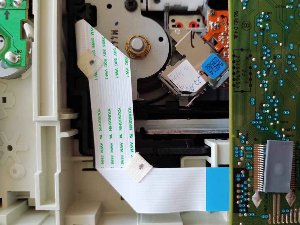
I dug up some DC DVD raft drives, they are nice mechanisms:
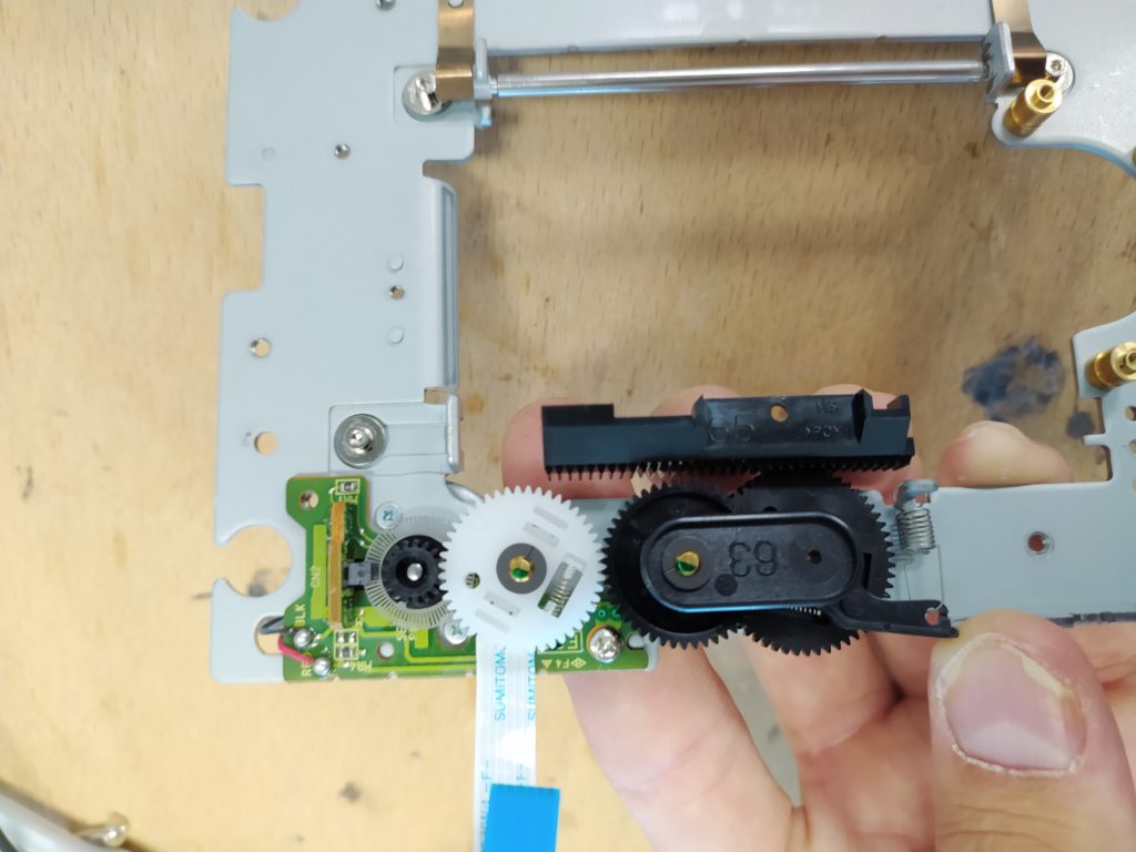
The black rack was attached to the raft.
I tried powering these with Wilf’s SPSH circuit and the bearbones solar head and they were too big a motor to be powered unfortunately. I could still try to increase the 1381 trigger level with a resistor though…
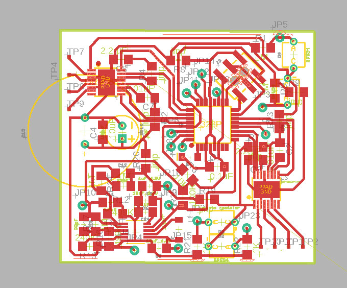
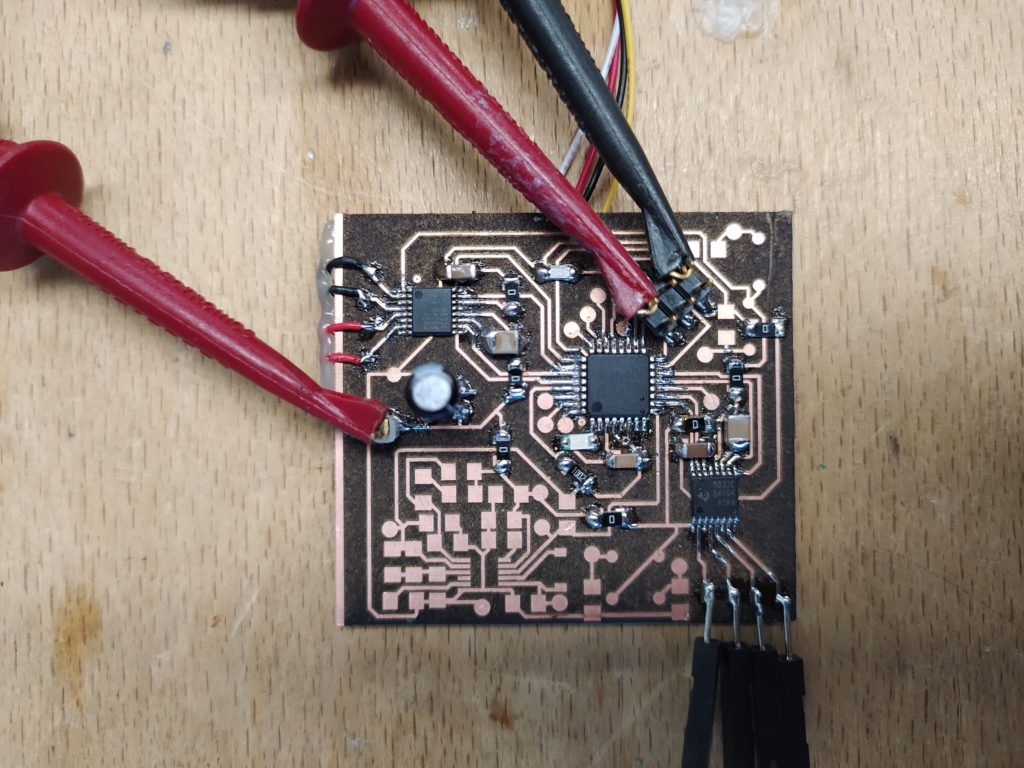
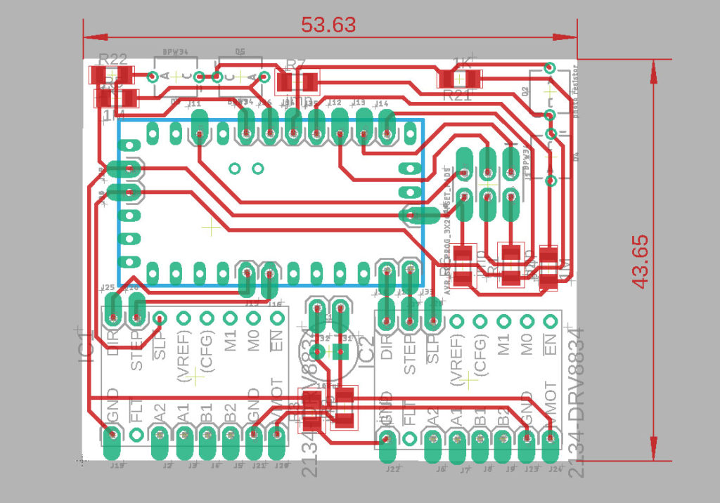
I’ve redesigned the microchip version of the board to make the wiring to the stepper much easier this time. I’ve also added two caps to smooth out the motor supply.
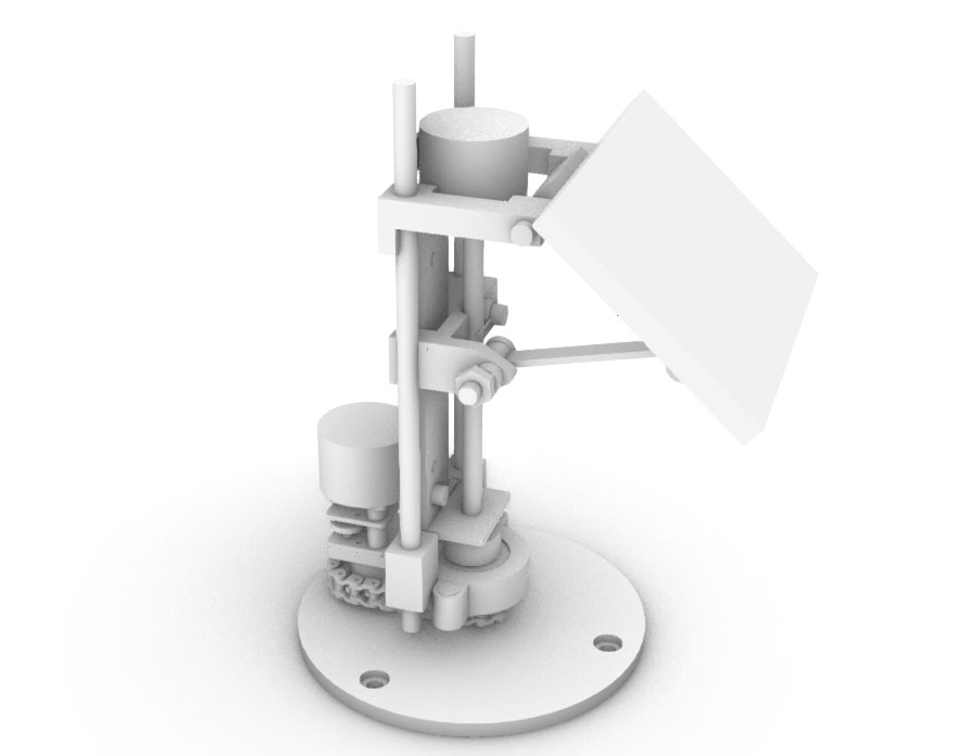
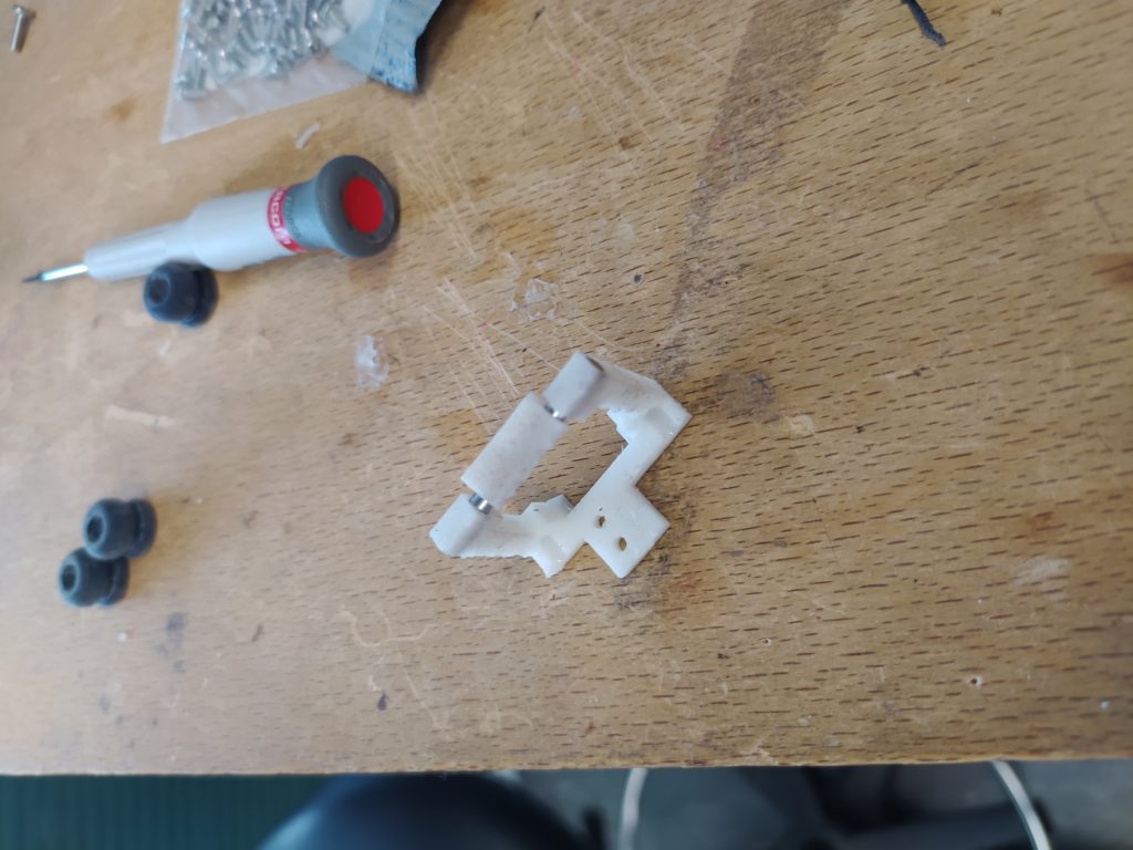
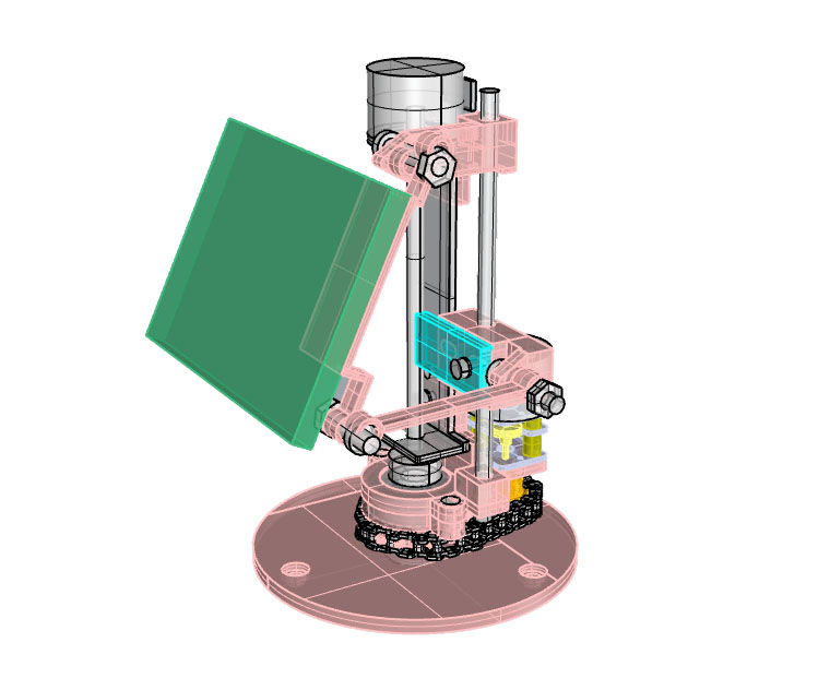
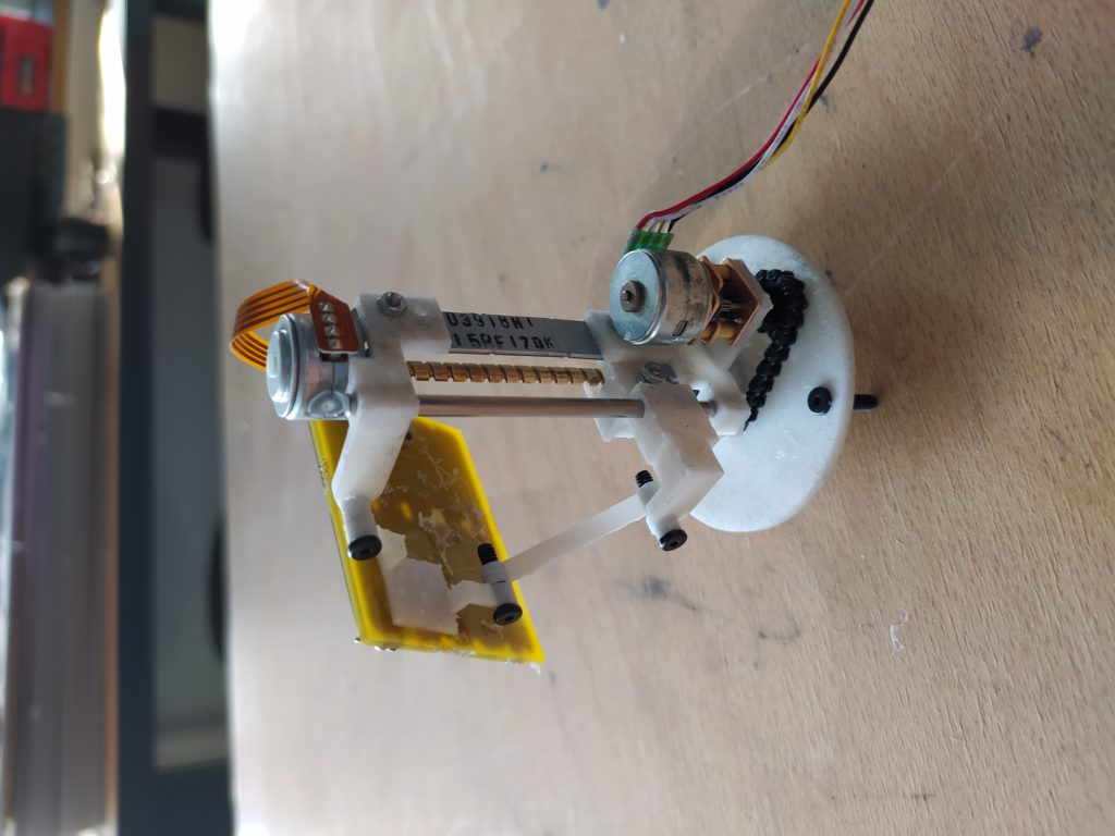
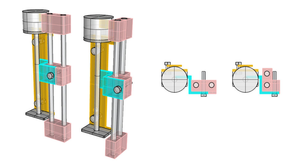
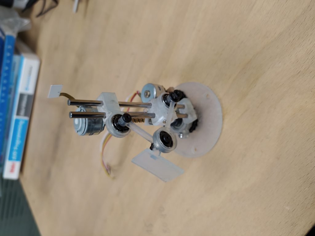
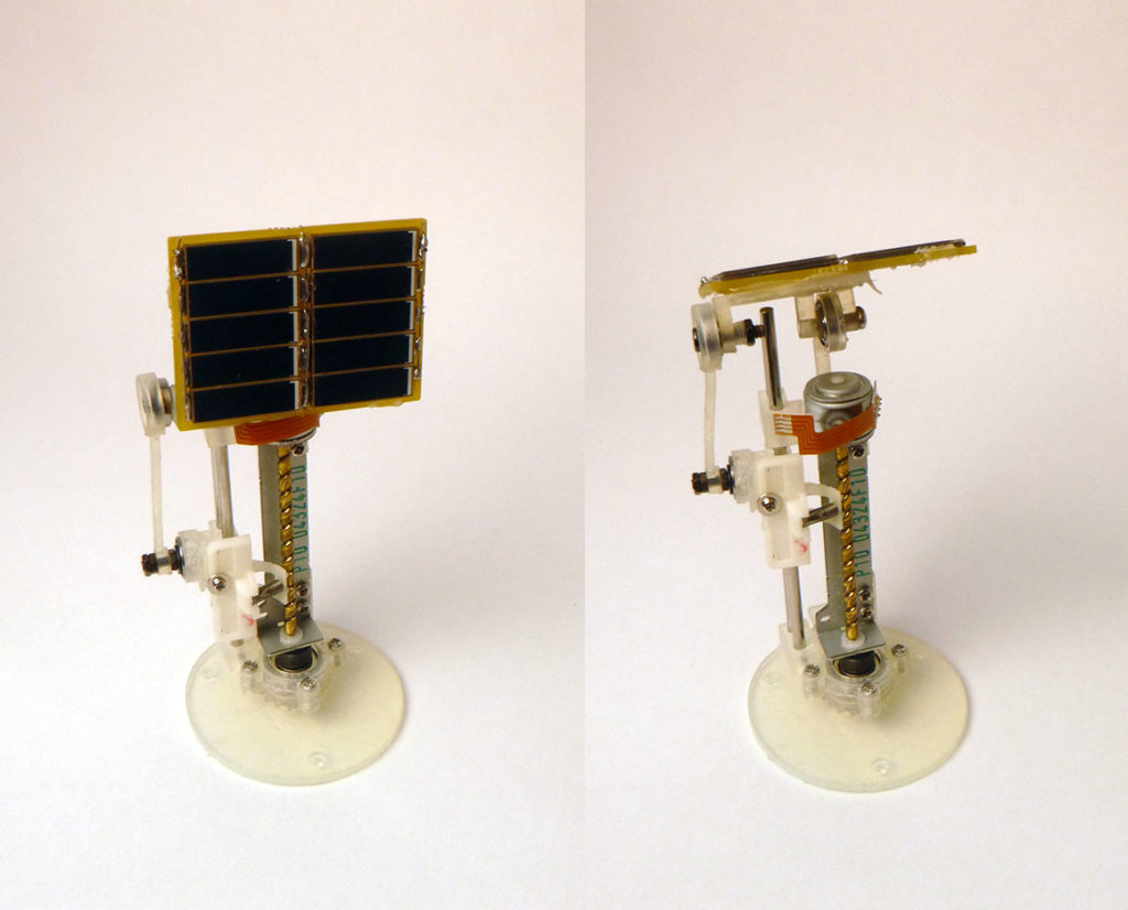
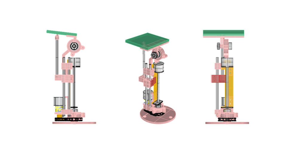
And here is a more robust version of the previous two stepper, this one has two parallel bars, a more robust hinge, and the lower bearing is encased completely for more stability hopefully. I am also getting rid of the lead screw plastic piece and trying to replace that part with a thin metal rod. In general it’s simplified and a bit thicker all around :
I am using a dremel to clear out the holes before inserting things and this is reducing shattering of the more fragile white resin.
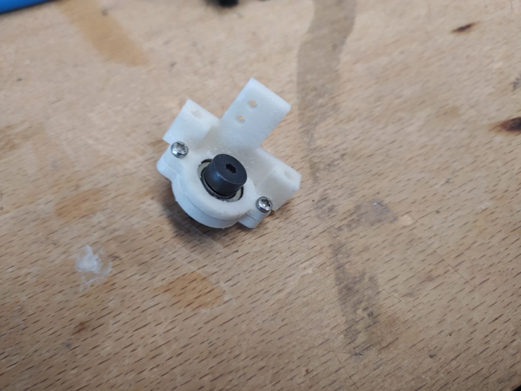
The bottom bearing:
Part of the solar panel hinge:
Only one of the two stepper drivers worked on this board but I haven’t found the issue yet…I wonder if back reverse polarity I destroyed it by accident or over heated it during soldering. I’m going to replace it with a fresh one and see if that changes anything.
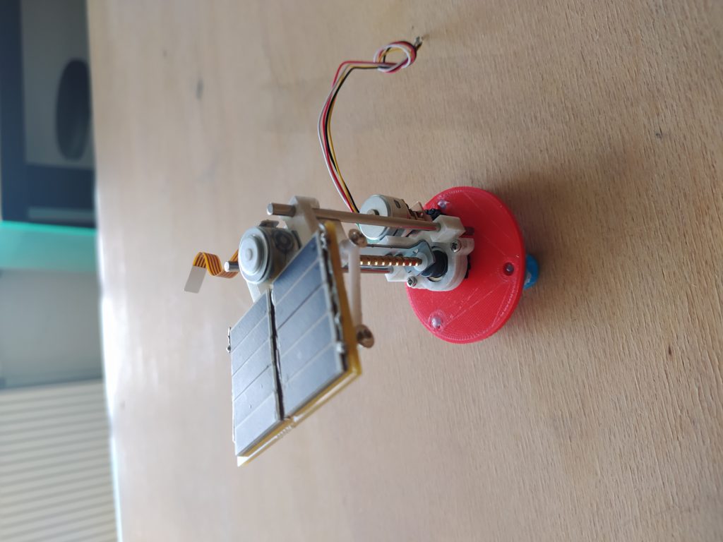
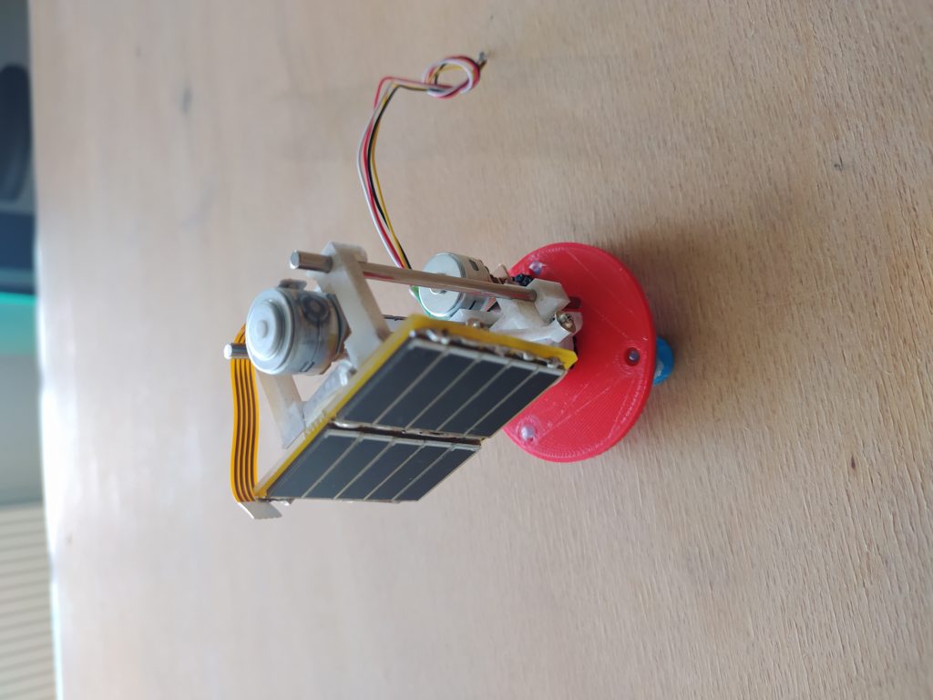
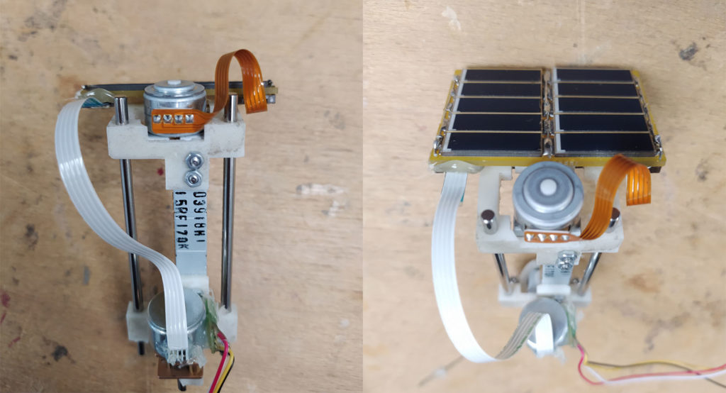
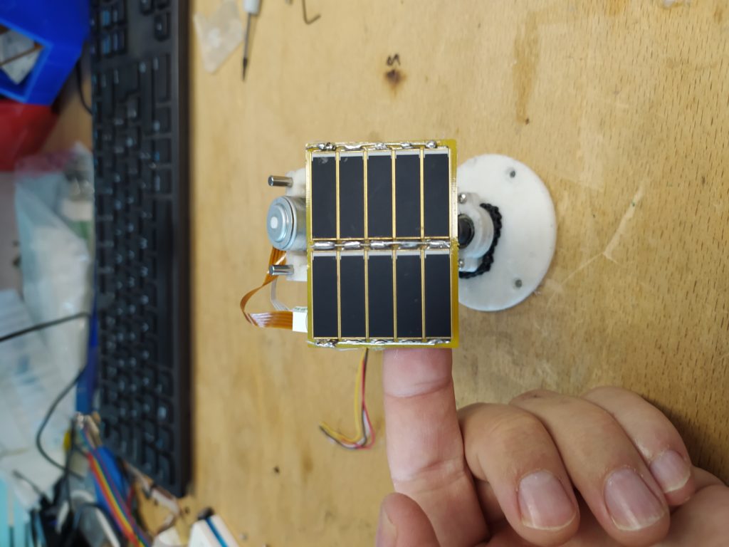
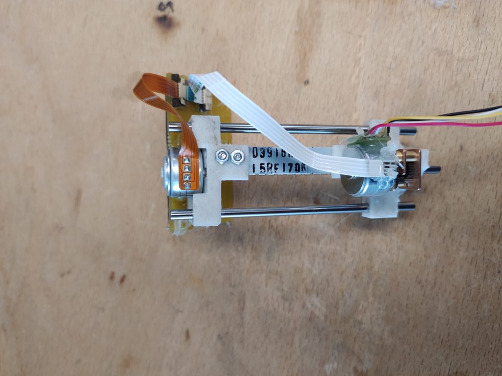
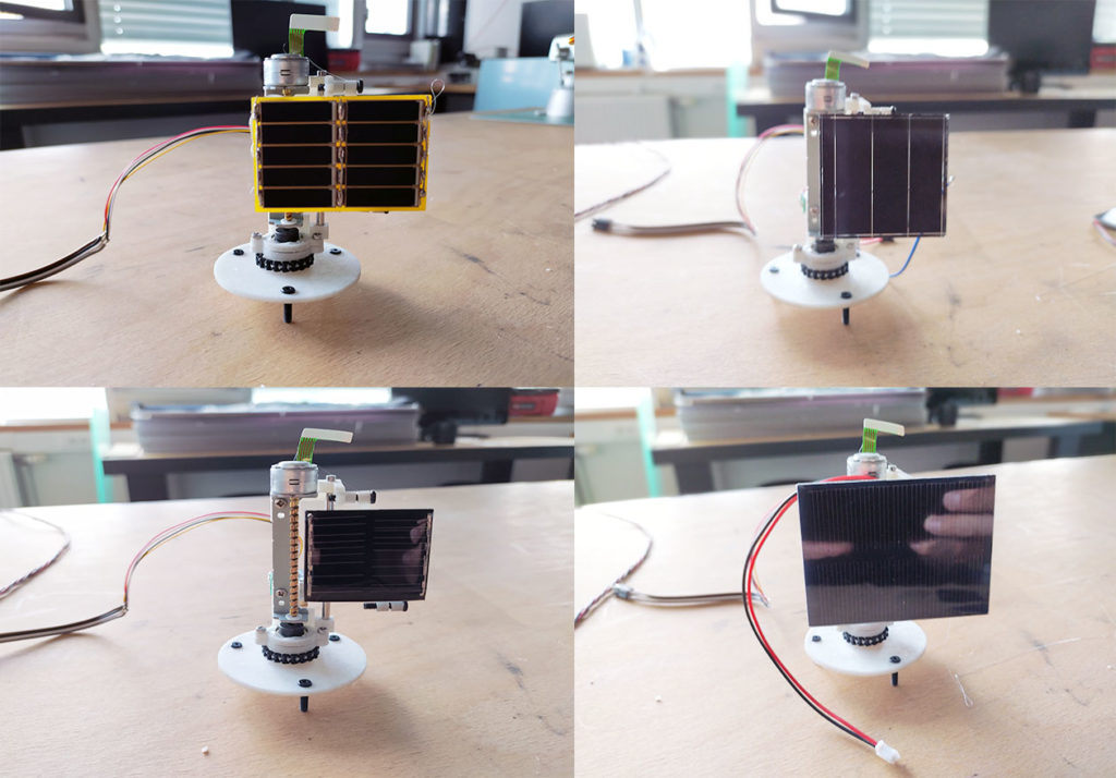
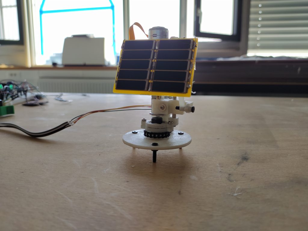
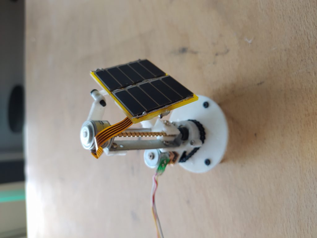
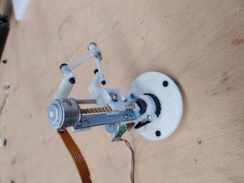
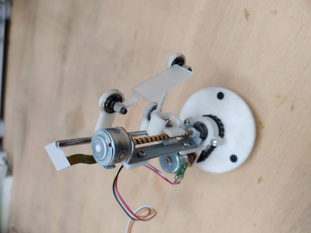
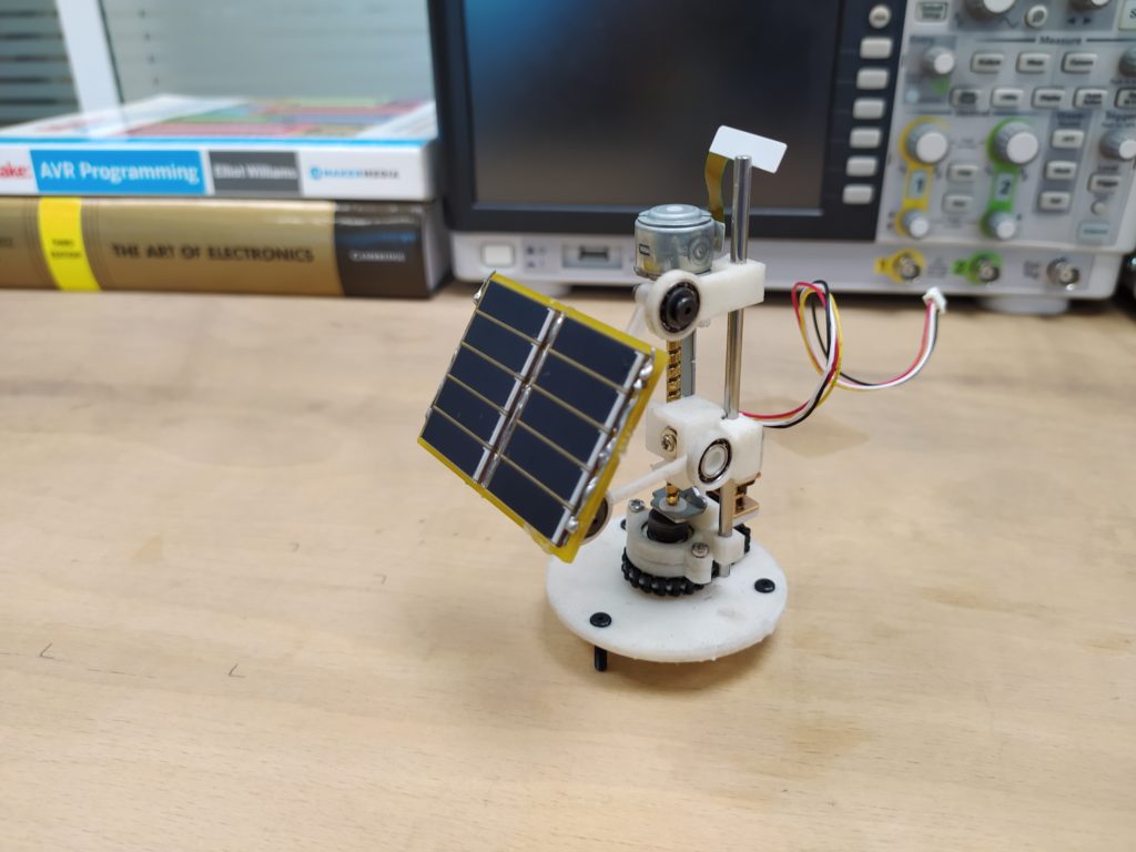
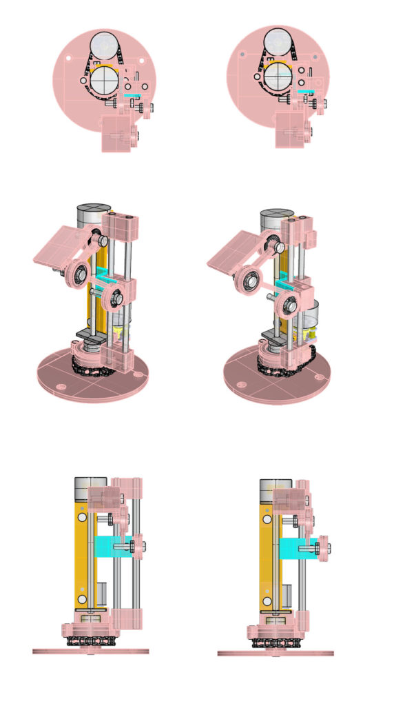
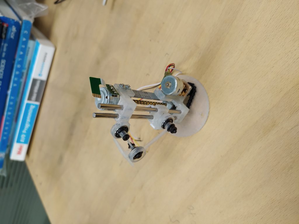
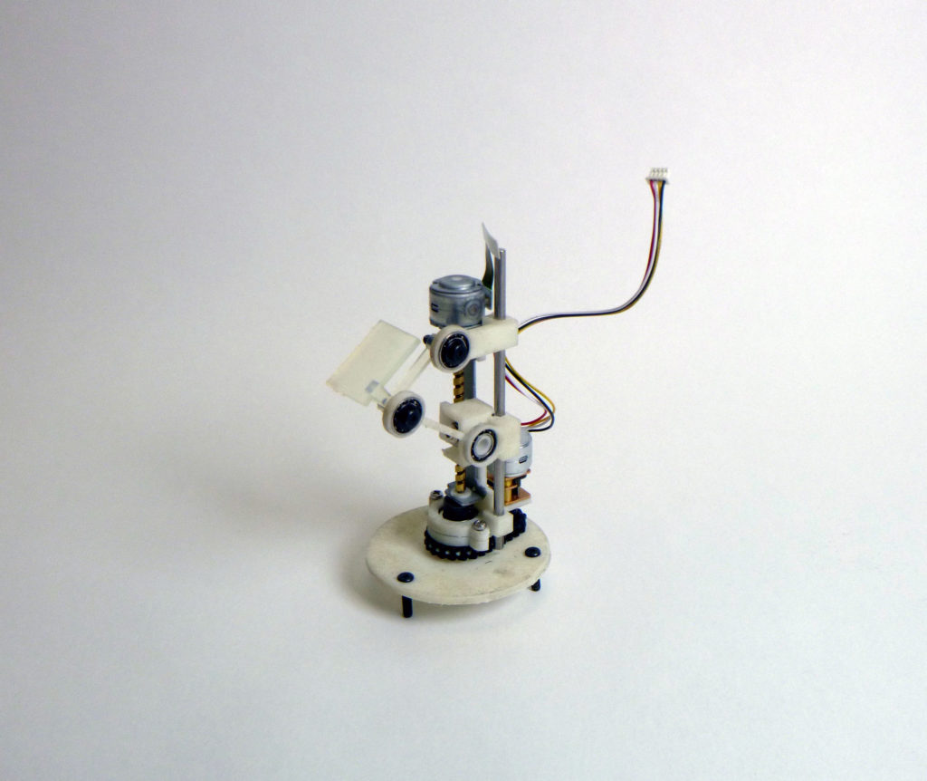
Here’s the assembled machine:
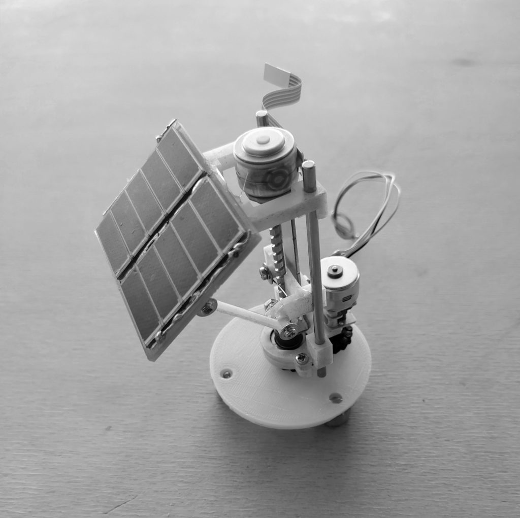
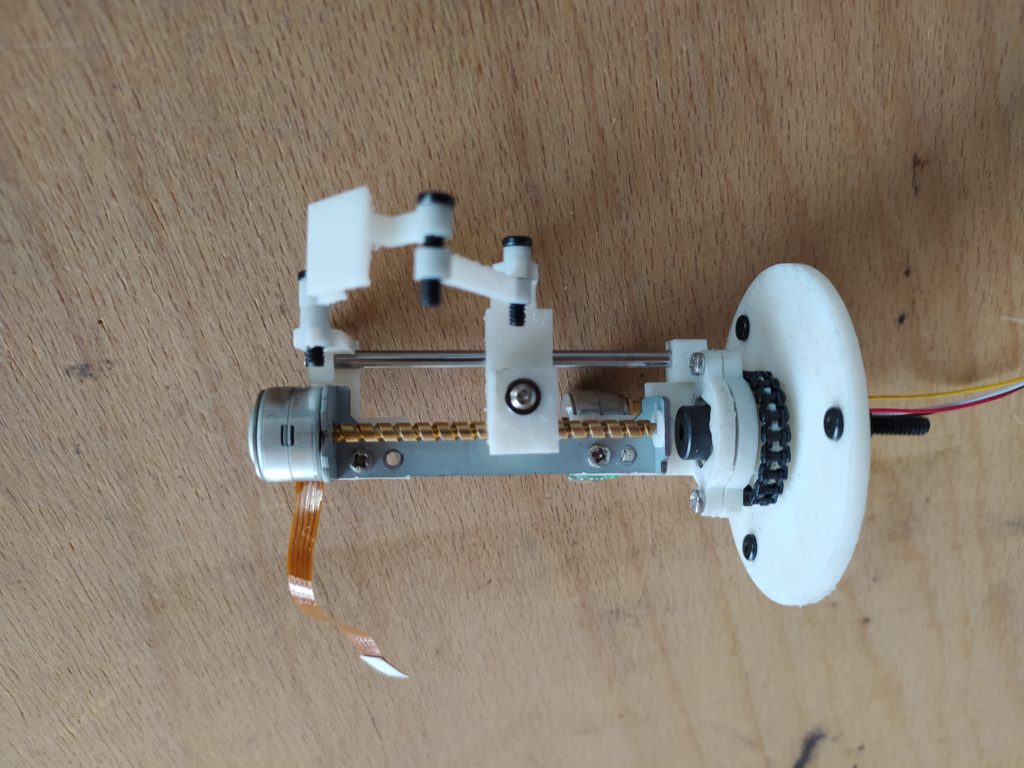
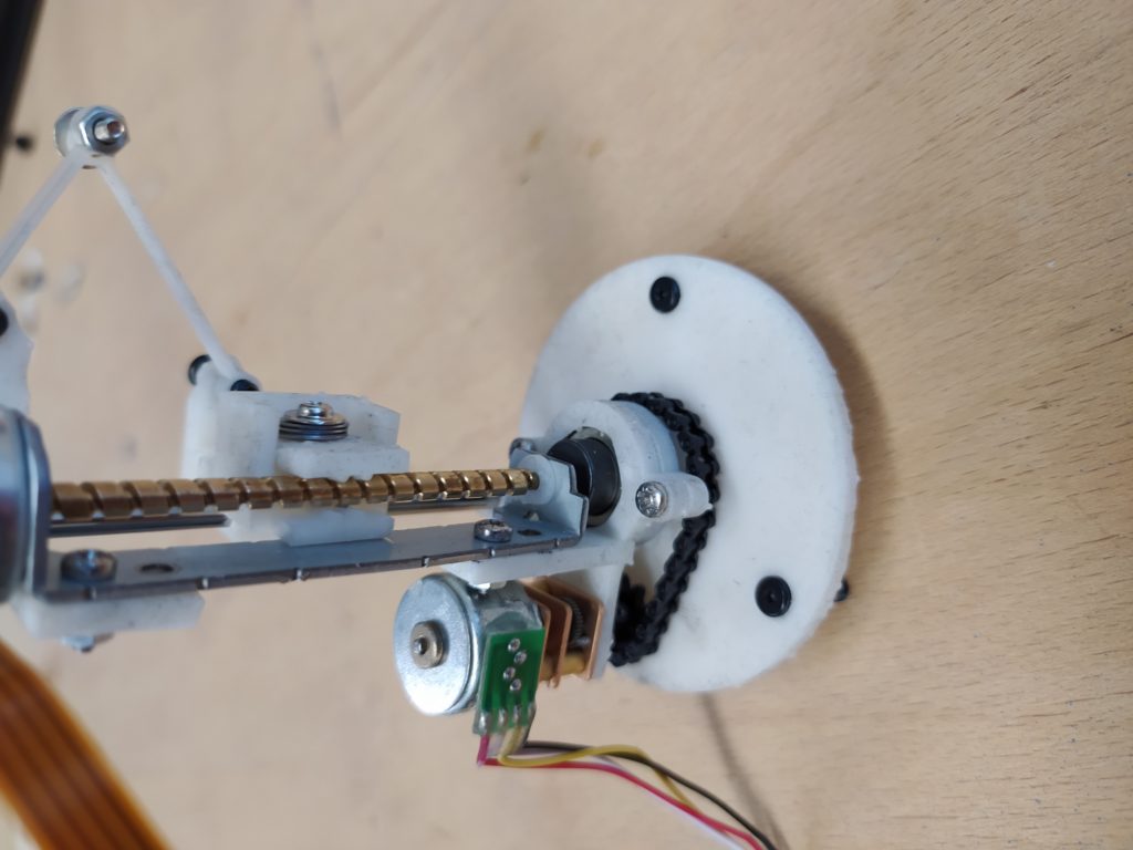
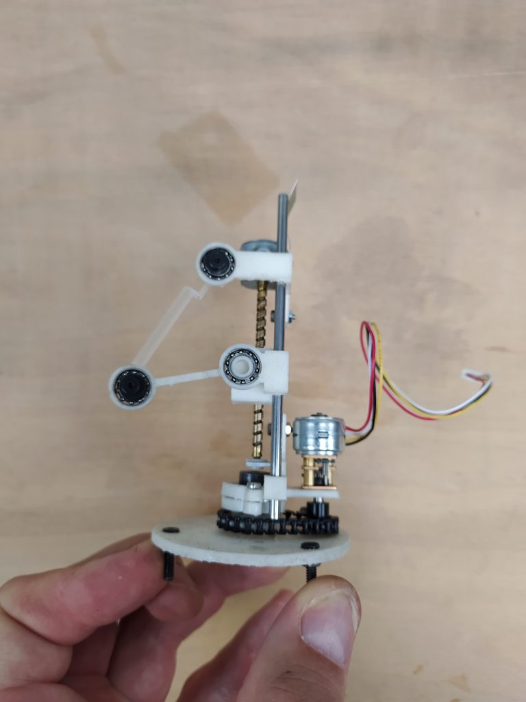
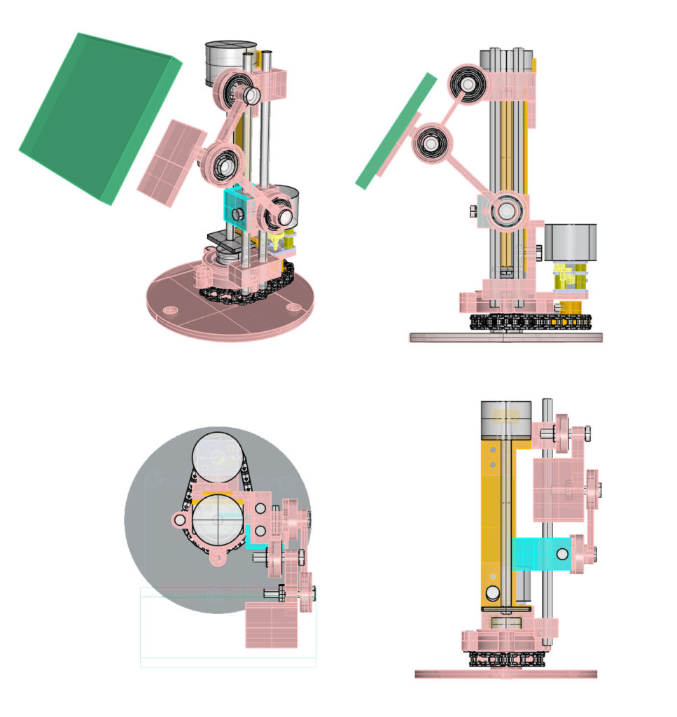
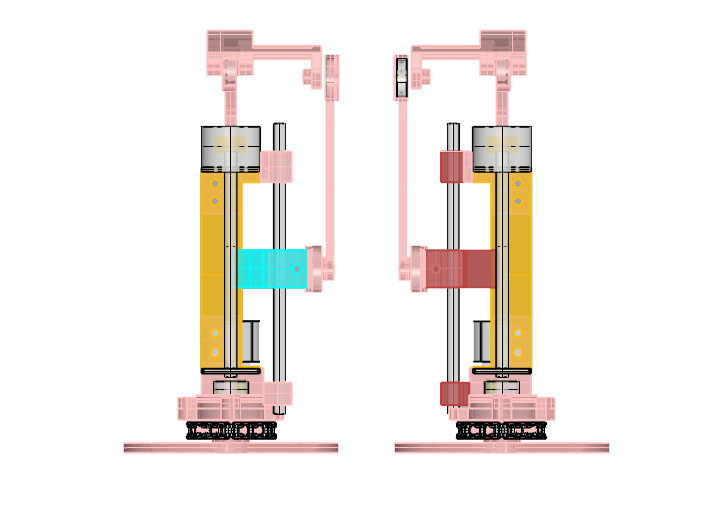
Here is a look at some of the technical details:
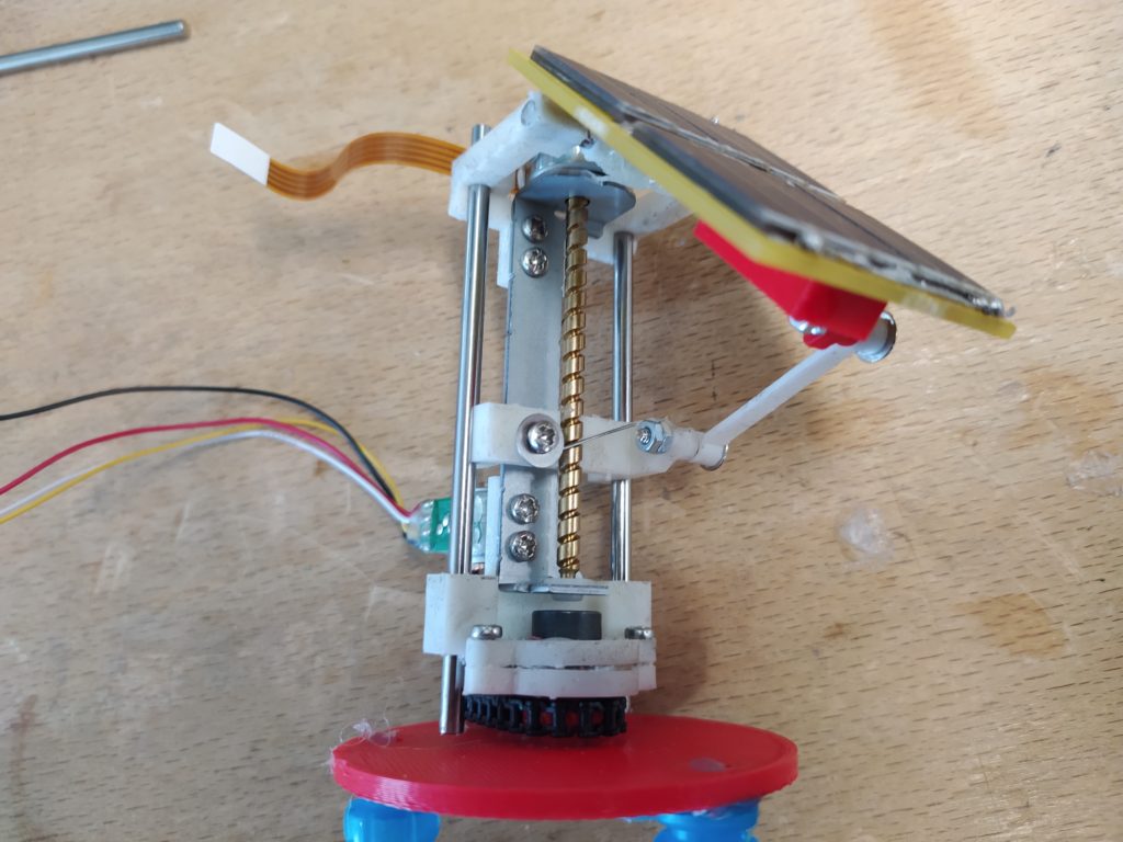
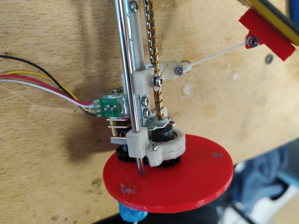
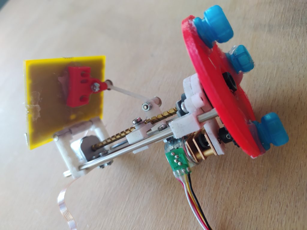
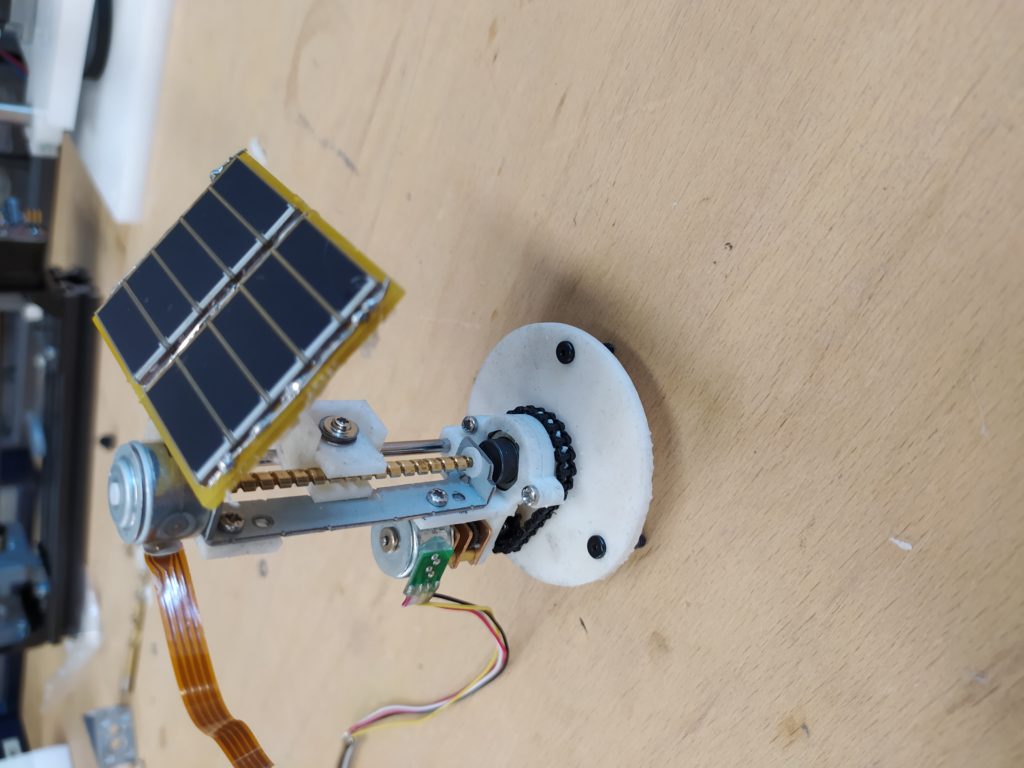
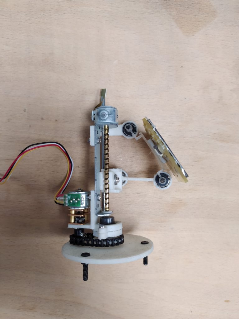
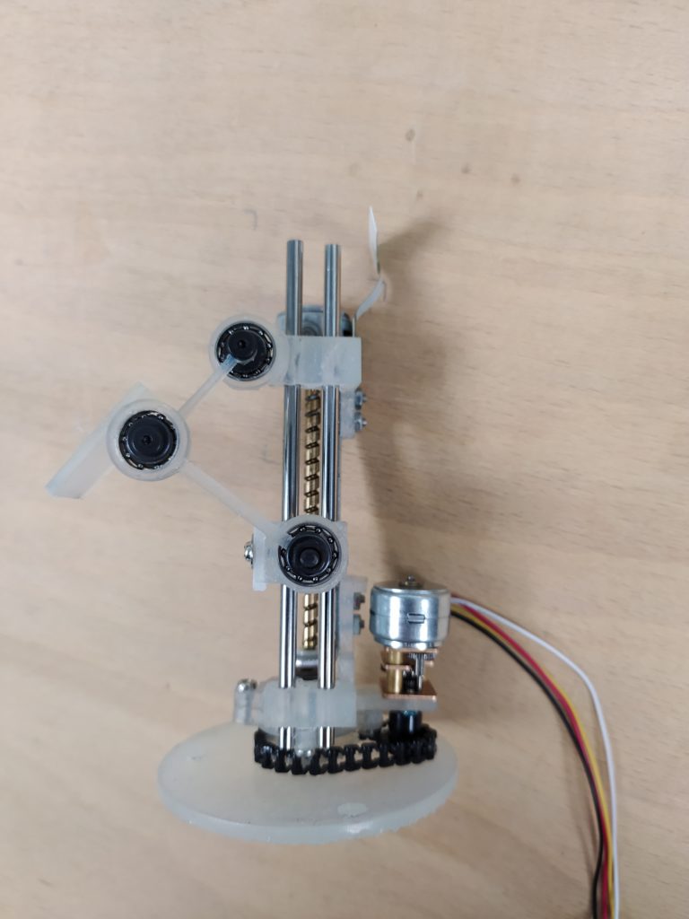
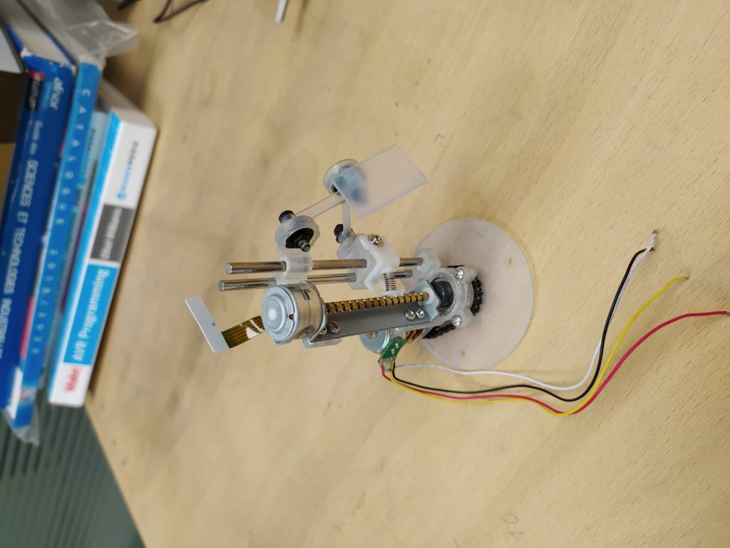
A different panel orientation option:

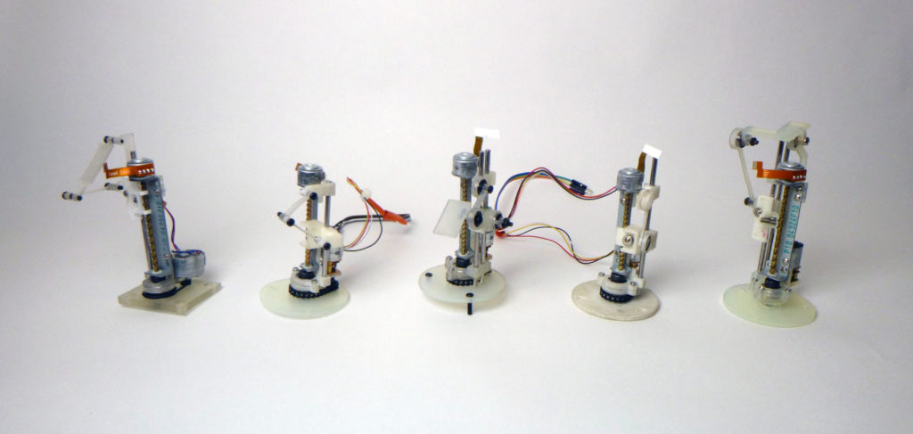
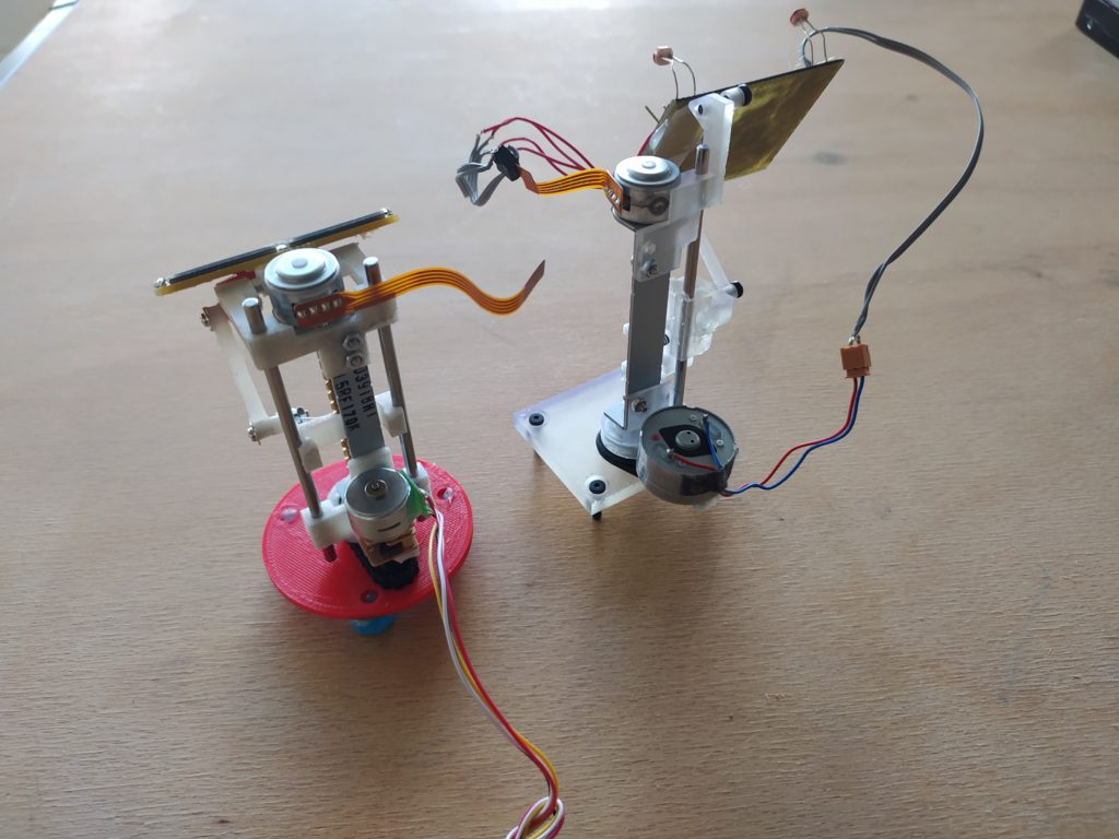
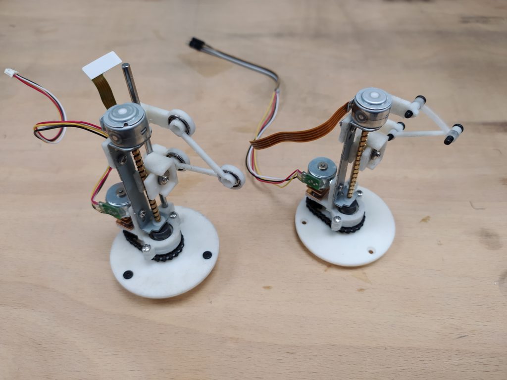
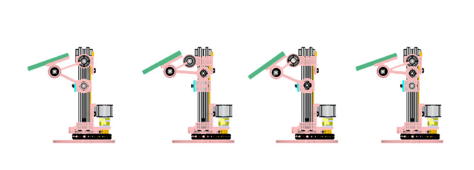
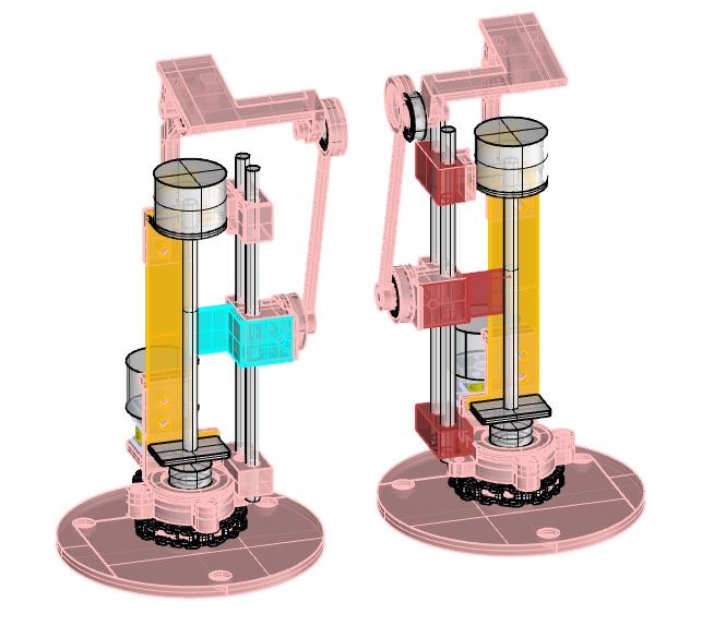
Comparing the two versions (the newer is far more compact and stable but less playful and off-beat/asymmetrical):
Check out the angle range, it’s better than I expected!
ERRATA:
- The idea of putting a pin accross to act as the lead screw is not working with only one side screwed in. AND the lead screw platform is impossible to insert into position (I had to break it in half and glue it back together once in position). I should definitely not try to go under the lead screw, with the nut that holds the pin, it actually makes contact with other nuts holding the whole linear rail assembly. I think I should go back to integrating the existing plastic lead screw – aesthetically it adds more flavour and asymmetry.
- The part that attaches to the panel should be one connected part because this gives more surface to attach to and more rigidity. (X)
- There is a volume which enters into the bearing socket that I needed to remove with the dremel. (X)
- The three bottom holes for screws are not evenly spread out around the circle. (X)
POSSIBLE CHANGES:
- Tensioner for bottom chain or larger bottom gear?
- The top hinge is too symmetrical for my liking but otherwise it’s super stable.
- Transparent resin is definitely nicer.
- The bottom nut needs a tiny bit more room, but it just works.
- The bolts are hitting the bottom stepper gearmotor.
Here is a new version which solves the errata, but it looks hideous:

I am considering returning to a one bar setup. I am also considering how I can make one version of this device that will work for the different linear actuating steppers and the different rotational motors (the micro steppers and DC gear motors have the same face plate thankfully). The top and bottom of device are also not connected (so varying heights of linear drives can be accomodated). Should one single design be able to work with belt drive or chain? I think I should now focus on producing a bunch of these.
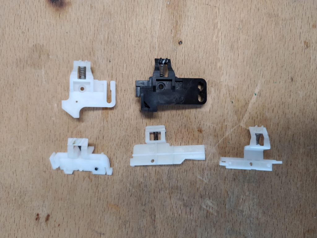
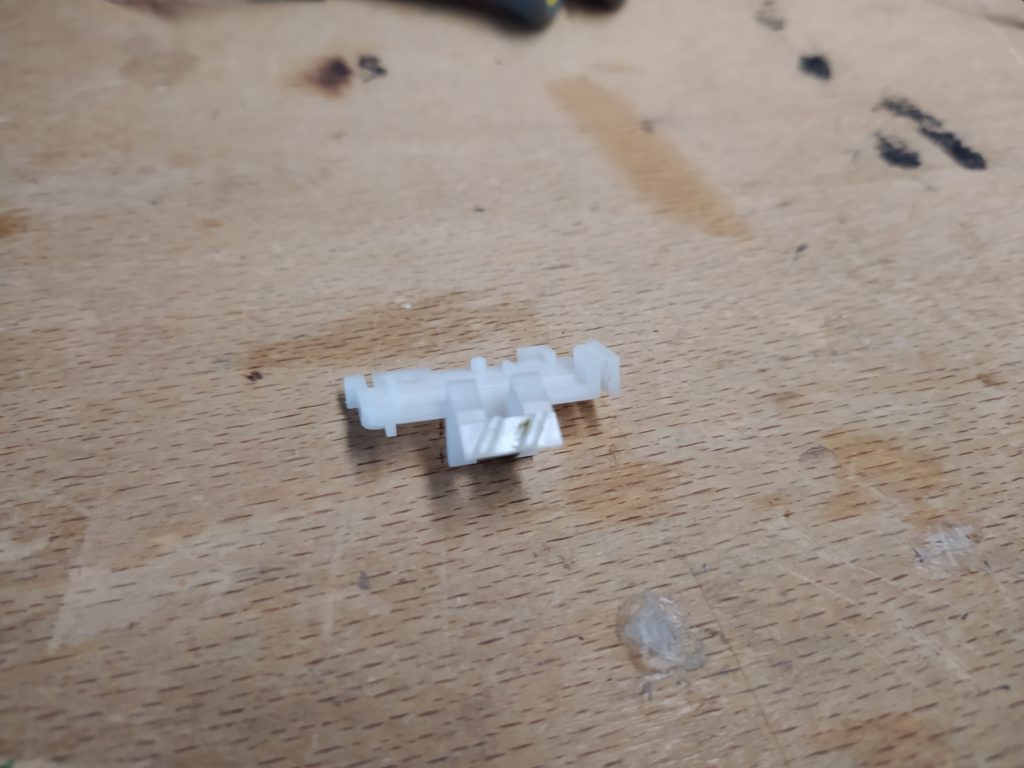
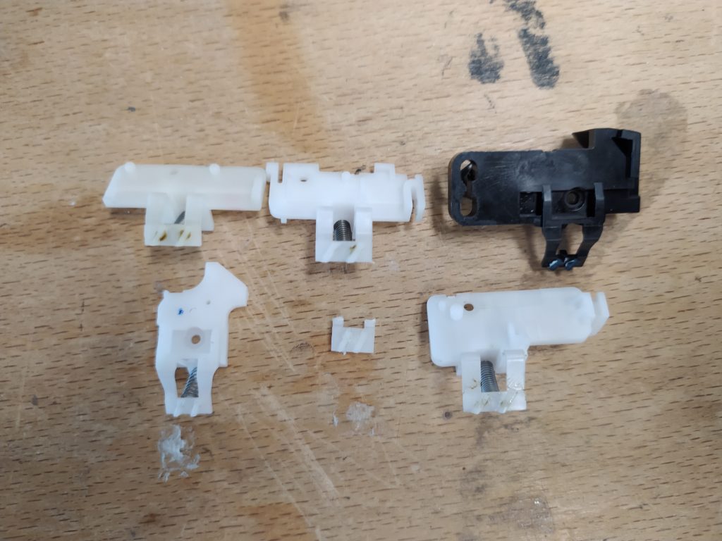
Here is how the little plastic parts that act as lead screws work:

There are all kinds of shapes but in the end they all appear to have one main screw location and a bunch of other nibs and slots to help with alignement. I can include a sliding slot for the main screw in the 3D print but I may use a dremel to adapt it to different nib locations.
 I’ve revisited the version 1 and have made the following changes:
- I’ve kept the more robust base from version 2.
- I’ve revised the lead screw plastic part holder and made the print compatible with the highest number of these peices and allowed for longer stroke.
- I’ve kept the magical setup that allowed for a great variation in the panel angle.
- I’ve kept the circular base which is more stable and made a larger base gear so it looks more stable. (The pitch of chain I am using is 0.1227″ https://www.mcmaster.com/miniature-roller-chain-sprockets/pitch~0-1227/)
- I adjusted the motor so the bolts are no loner hitting the bottom stepper gearmotor.
****
Wire management:
I like the ribon wires from the CD drives and the mini locking sockets and plan to use them:
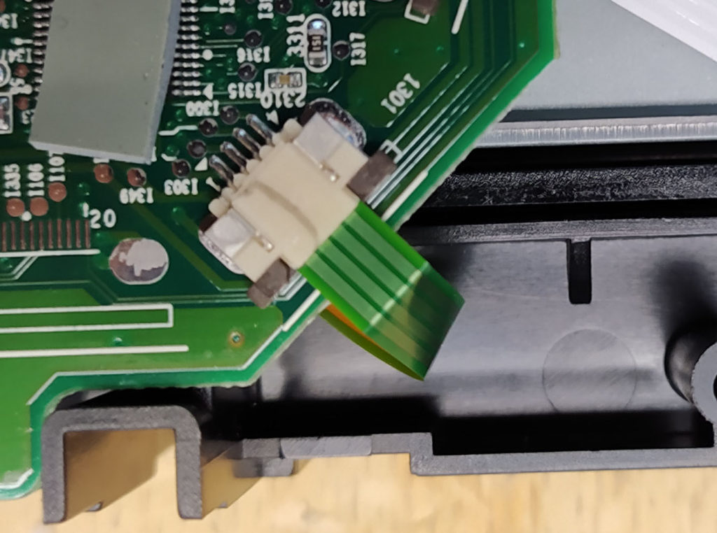
The top option seems sensible.
Here the bottom motor ribbon is going to be super stretched when the panel is at full extension in angle…
I like the asymmetry of the second option, it implies that the lead screw and hinge action is taking place on one side and the electrical connections on the other side.
(I’m just realizing that some of the ribbon cables that come with the stepper linear drive are not very long + the brown/orange doesn’t go super well with the white. Should I replace those cables with white ones so that everything is the right length and homogenous?)
There is also the possibility of folding the ribbon cable…
I’m trying to find this product (it seems to be called “flexible flat ribbon cable”) but not having luck on Farnell or Mouser (*correction: https://www.mouser.fr/ProductDetail/Wurth-Elektronik/687606050002?qs=qR1qlUC5%2FYSp8nXHAtNchQ%3D%3D) …Here it is on Ebay and Amazon:

The other option is to harvest wire from the old CD drives I have, the wire lenghts seem to vary from 8-11cm.
Some solar panel options:
****
Next version sucesses:
orienting parts so that the supports don’t touch faces that will be seen is a good idea, it saved the bottom platform from pockmarks.
Errata:
- The main issue is the lead nuts. They are massive and therefore reduce the stroke considerably. Most have a setup where they push against the leadscrew and twist the sliding cam which is now only fixed to one rod. I should try to design the nut myself, if the solar panel is in the middle it is hidden in any case. The other option is to find another one in a million lead nut that works like the one in version one where it doesn’t push against the cam / use two bars. (X)
- Somehow the ratio of arm lengths is producing a totally different range of angles, mostly in the negative direction! (X)
- the layer on top and below of the bearing is too thin and comes out wavy. (X* I did the top visible part but not the bottom).
- missing a subtraction around the collar of the bottom stepper motor shaft. (X)
Possible changes:
- all black hardware would be nice. Or perhaps all white?
******
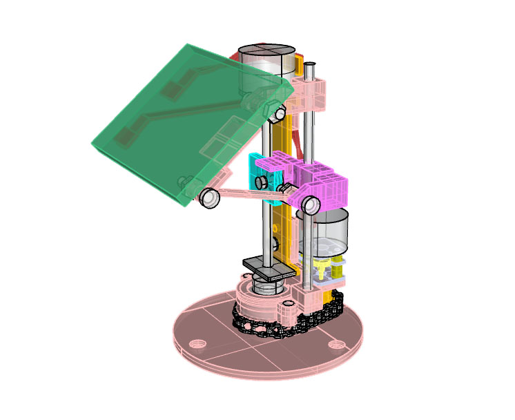
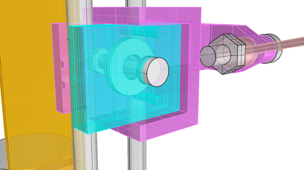
Modeling the lead screw:
The threads themselves:
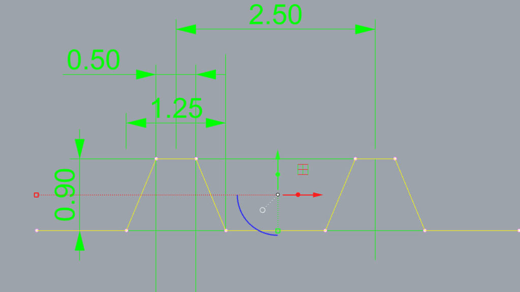
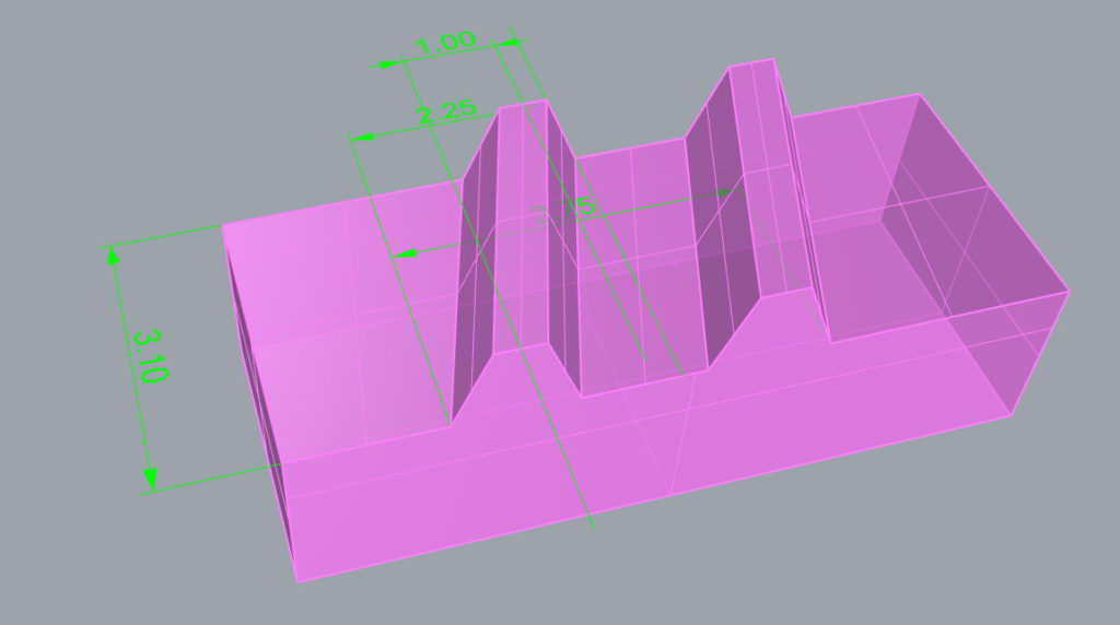
I want it to be possible to adjust this thing so I am planning to use a stack of washers to accomplish this. I am also adding a notch in the purple volume to prevent the green volume from rotating. It should also mean that the green volume can be made to accomodate different threads and the purple volume will still work regardless (i.e. it’s modular).
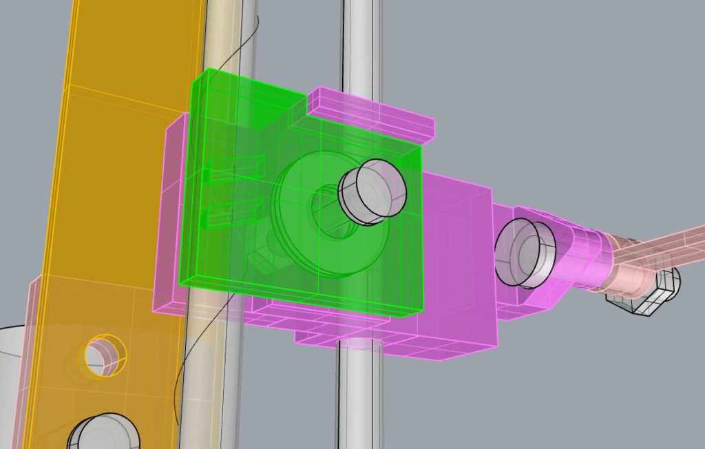
The backside leaves space for a nut to fix the green piece in place at the right height.
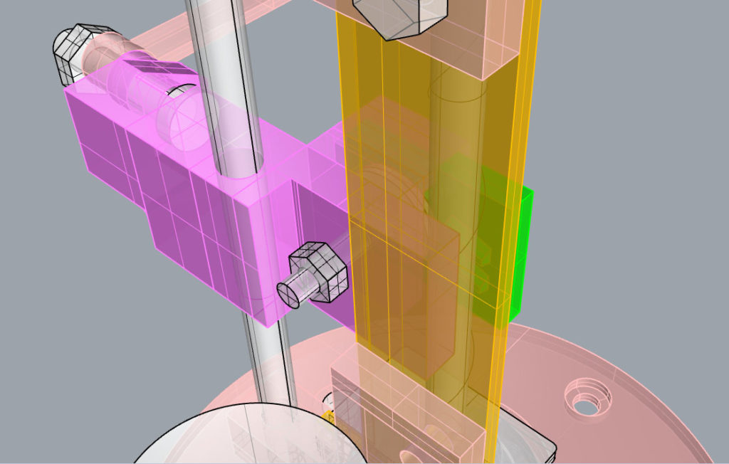
I’ve also adjusted the angles to match the version 2 as exactly as possible this time:
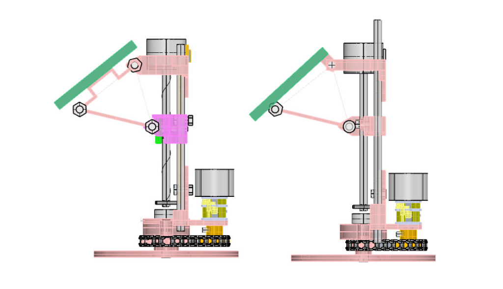
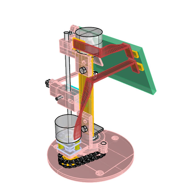
Here is the finished version 3:
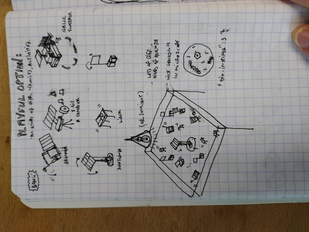
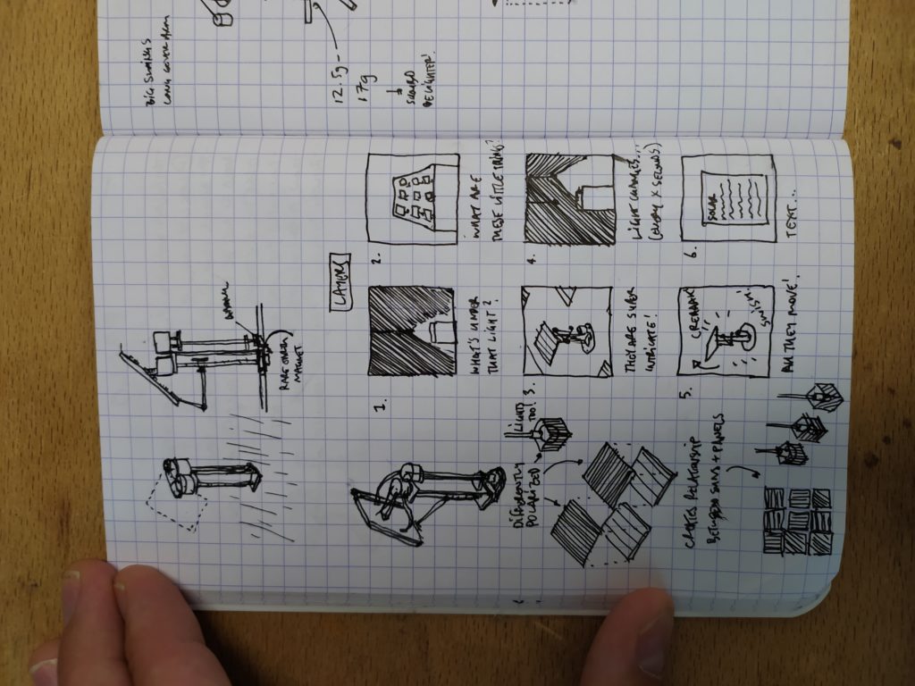
Some quick ideas about how this project could be displayed in an expo:
1. I can make a bunch of solar critters that react to the sun in different ways (sweeping in circles, following the sun but staying in place, making sound by tapping the ground or playing a song, etc.). This is the kind of ludic, “diversity of nature” bio-inspired option. The robots are indifferent to one another but occupy the same space. I’m not sure how to chose the materials but maintain difference/cohension of the group but presumably I could pick a kind of 3D printing and use the same motors.
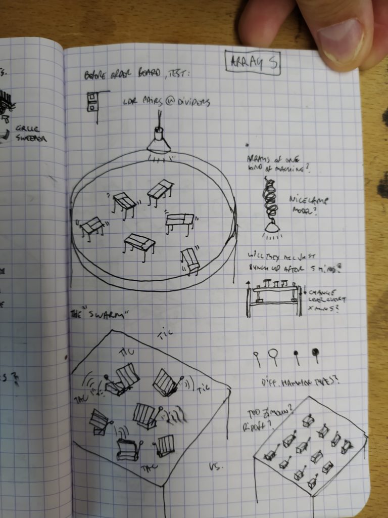
2. Make one such critter (like the sun follower) and create an array of them in a given space and watch the group effect of their behaviour. This is kind of obvious but at least it’s abstract and sober, hopefully fitting in my portfolio with my other more abstract/representational work. It would also be easier to mass produce one design than to make a bunch of one-off designs I think.
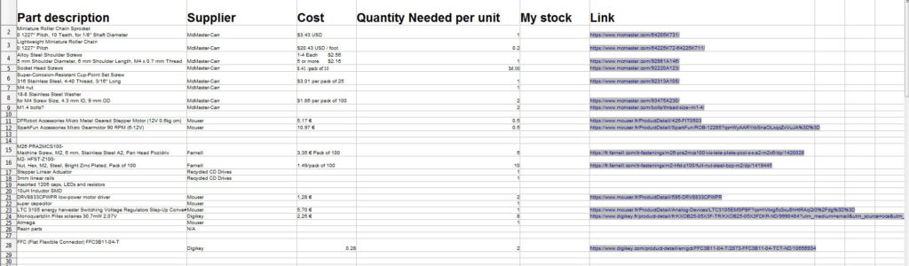
And here is the BOM so far:
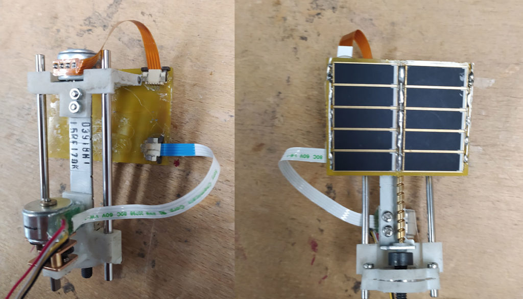
And here is the newest build:

ERRATA:
- The lead screw does not work. It is not perfectly aligned with the threaded rod and the system for holding it tightly in place is not working. I think I need to put the lead screw on the bottom side of the threaded rod and have a tensioning mechanism on the front (accessible) side.
- The angles are still wrong. If I make the top arm (that is glued to the solar panel) shorter I think it will improve.
I’ve put the lead screw on the back of the threaded rod and inserted alignment rods and increased the borders to hold the top piece in place:
****
The solar panel angles are fixed! With two of the threaded nut sides making a sandwich it does actually work as a lead screw nut (even though it really doesn’t look nice) !
***
Thoughts from artist Paolo Salvagione:
- Make a power budget (what does everything i.e. steppers, microchips, drivers use when not on, when on)
- Run motors 24/7 for weeks before to test that nothing falls apart.
- Replace bolt hinges with flanges or miniature bearings from McMaster Carr. (The smallest available at a reasonable price is 5mm OD no flange).
- Try pulling up everything to the top beneath the board and alternatively pushing everything else to the ground to create a sunflower.
- Think about the center of balance of the machine and how you can place it directly over the pivot point (or move it there with weights).
- What kind of choreography would I like to see here.
- Alibaba has super inexpensive solar panels that look great.
- Could the array relate to different light sources which exist in a kind of solar system around the plinth.
- How can visitors experience this piece at different distances (“layers” of experience)?
- Medium-runs of a finished design are easier than making a ton of one offs or mass producing.
- It’s possible to order flexible PCBs from PCB Way.
****
Some thoughts on the layers possible:
I have found a few 10mm OD bearings and will redesign the arm portion with these:
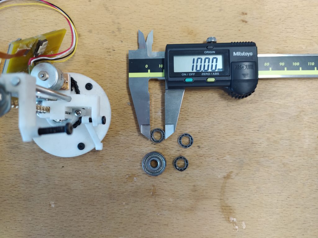
I’m not totally satisfied with the bearings in the design (McMaster has perfect 5mm bearings that are reasonably priced but they don’t ship out of the U.S.).
****
Calculating the balance point with help of this site: https://www.school-for-champions.com/science/gravity_center.htm#.X2B-cFUzaUk

CG = (aM + bN + cP)/(M + N + P)
Seems like I should try to keep the solar panel light in general (under 12 grams?), but that I have the option of adding some weight above the stepper in the rear. In the other axis I can shift the solar panel a bit to the side to compensate for the weight of the bearings in the arms.

****
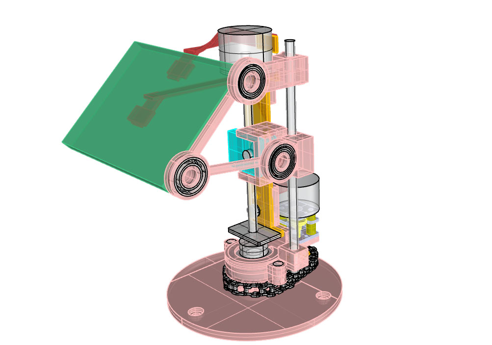
New version with arm bearings:
It was hard to attach the solar panel to that arm model so I switched it for one with mini bolts:

I don’t like the look of the three wide and narrow bearings so I am trying to hide one under the panel and switch up the second by putting the black bolt through it. One of these only would look great but three is too much.
A new design with McMaster 5mm bearings (I can in fact order them it would appear). In one I keep a single large bearing and in the other all the bearing are small:

Making a third prototype to test the following things:
- Durable resin for everything but especially for the lead screw.
- Adding flanges to hold the current bearings in place.
- Slight tweak to the currently improvised lead screw design.
- Fix angles again with shorter arm.
- Hiding the other bearings a bit under the panel.
- Making a third so that I can begin testing the “swarm” effect of the robots actually moving.
****
I began two stress tests based on Paolo’s advice:
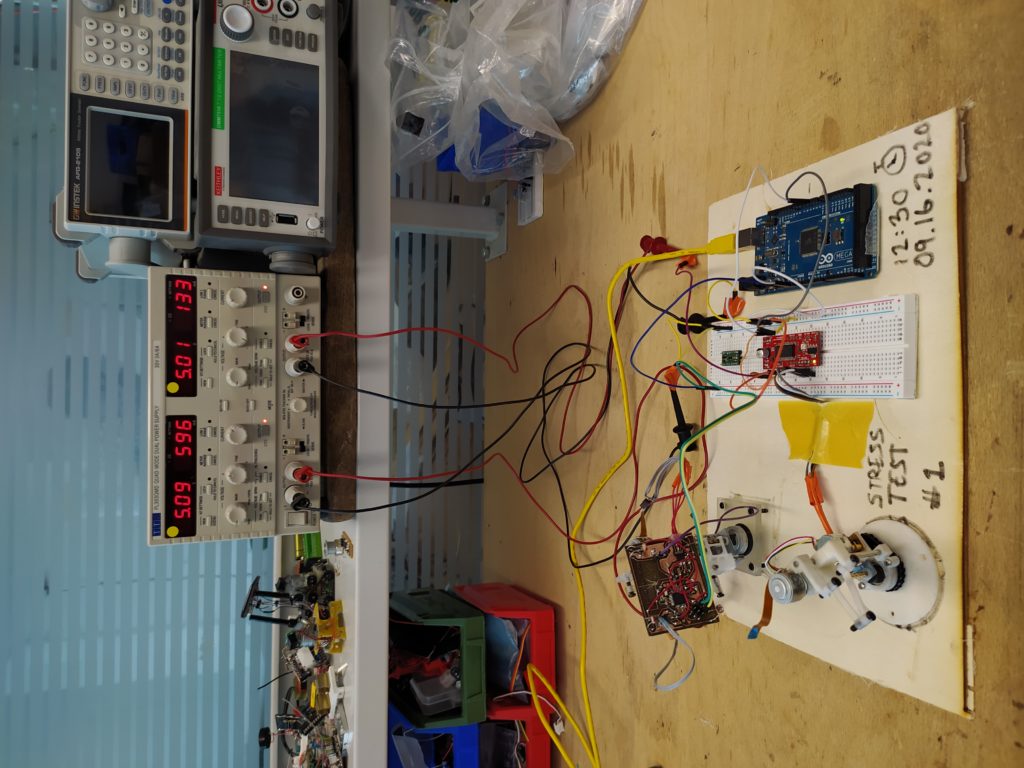
Some things to note:
- These are so much fun, people visiting see what you’re doing as Paolo suggested!
- It fights anxiety – you know if it will work or not.
- Working for 1 minute is not the same as working for two weeks 😉
Unfortunately there is a serious issue: The linear drive is drawing 600mA at 5V to move up and down…I should try to mess with the steps and speeds to see if I can get this down. The rotating motor is drawing less than 150mA.
Looking on Alibaba, the most popular size of smaller panel is 156mmx156mm. But also found some 47×47:
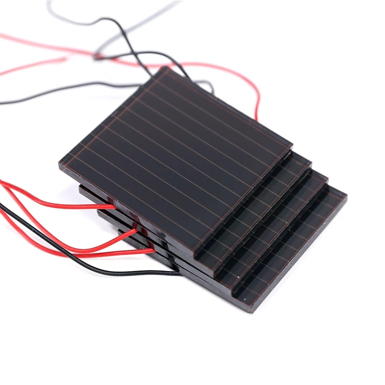
and some 55mmx14mm
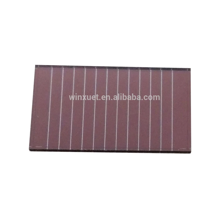
37×21.8×1.1mm
Here are the best links I’ve found so far:
https://www.alibaba.com/product-detail/55x14mm-3-0V-7uA-dim-light_60585863880.html?spm=a2700.galleryofferlist.0.0.43be4630X6CXwJ
https://www.alibaba.com/product-detail/Dim-Light-Amorphous-Silicon-Thin-Film_208238751.html?spm=a2700.details.deiletai6.5.561929devzX1BP
https://www.alibaba.com/product-detail/3V-10uA-Dim-Light-Amorphous-Thin_62187655652.html?spm=a2700.details.deiletai6.1.561929devzX1BP
https://www.alibaba.com/product-detail/37×21-8mm-6V-2mA-outdoor-used_60506651563.html?spm=a2700.galleryofferlist.0.0.2430367cO11E7R&s=p
I sent my first email:
Hello,
I’m a research engineer at the Universite of Paris Sud in France and an M.I.T. graduate.
I’m working on a low-power solar follower product and reqiure small cells like yours to create a series of panels (with each an array of 5×2) to combine with an energy harvesting IC.
I am interested in your product and would like to request a sample if possible to test with my setup.
Thank you ,
Jonah Marrs
*********
Easy stepper motor driver can drive both steppers at around 150mA at 5V with no load.
The DRV8833 with correct step and speed settings can drive the linear with the plastic lead screw found in the CD drive at around 360mA but has a super high idle current of 600mA. It gets super hot as a result. The DRV8833 cannot drive my lead screw setup however… Basically there is too much friction in my lead screw design currently. So, the conclusion is that it’s possible to drive this thing if I put the driver to sleep and I use the existing lead screw.
I am leaning towards using the found CD drive mechanisms (because they are perfectly made to minimize friction etc. already and look super cool) and add a second bar parallel to the first to improve stability and compensate for the rotating that the plastic lead screw wants to do.
I’m also adding another bolt to the bottom angle bearing, and looking for some 3mm bushings to add to the sliding portion. Here seem to be the two primary options:
The side by side bars on the left are less flexible with different found lead screws as the bolt location can’t move much to either side. It also makes the front part flatter and longer, whereas the bar behind makes the design feel more three dimensional and compact.
I prefer the bar behind.
Bending joints options:
I like the asymmetry of not having the top and bottom joints unaligned in elevation and in plan views, it feels more dynamic and optimized. I like the bottom bearing being centered with the cam.
Hopefully this version will allow me to do some stress testing with the tilt mechanism.
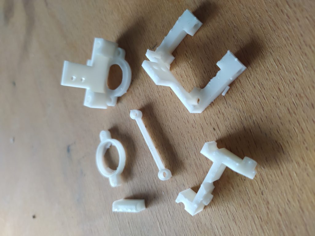
Here are the parts laid out:
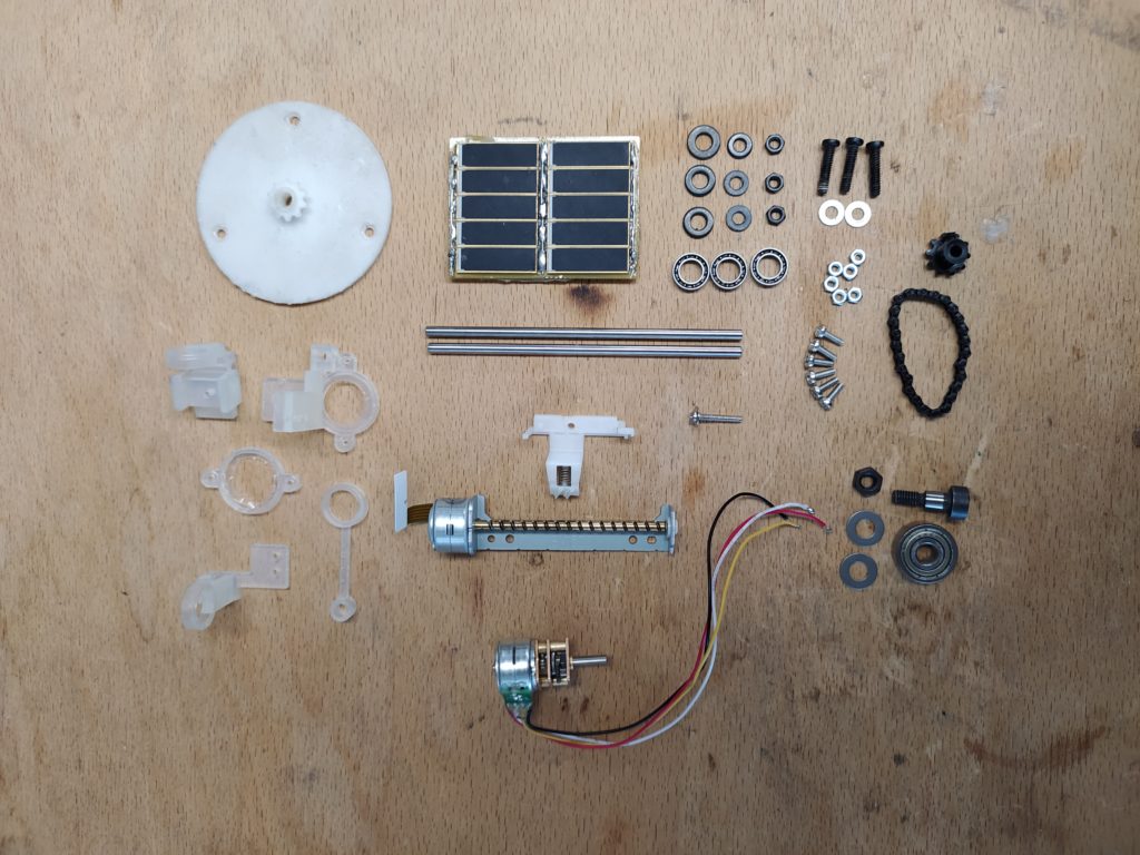
The assembly turned out well:
ERRATA:
- The lead screw is a tiny bit too high above the threaded rod, I had to carve out some material with the dremel…
- The elbow joint connected to the cam can’t work with a captive nut the way I originally concieved but it can work with the cap of the screw in the place of the nut.
- The set screw for the sprocket needs to be almost flush with the sprocket surface to not hit the bearing squeezing screw. The bearing squeezing screw between the parallel bars needs to come from the top not the bottom or else it interferes with the chain.
- I think I need to shift the two bolts that hold in place the bottom motor 90 degrees. And I may need to add a little circular band to keep this motor straight. A tiny drop of hot glue solves this…
- The solar panel surface is not flat but tilts inwards.
I got the test set up working again with two Easy Stepper Motor Drivers (with Enables and 5V+ connected also) this time. Now the bottom motor is driving 100mA and the linear is pulling 200mA. Both are cool to the touch. However, there is a little bit of power lacking for the linear lifting motor and it is skipping some steps. Switching to 1/4 instead of 1/8 microstepping, and making sure all the bearings are set up smoothly, appears to mostly fix this though.
Some experiments taking nicer photos:
A with and without solar panel gif:

*****
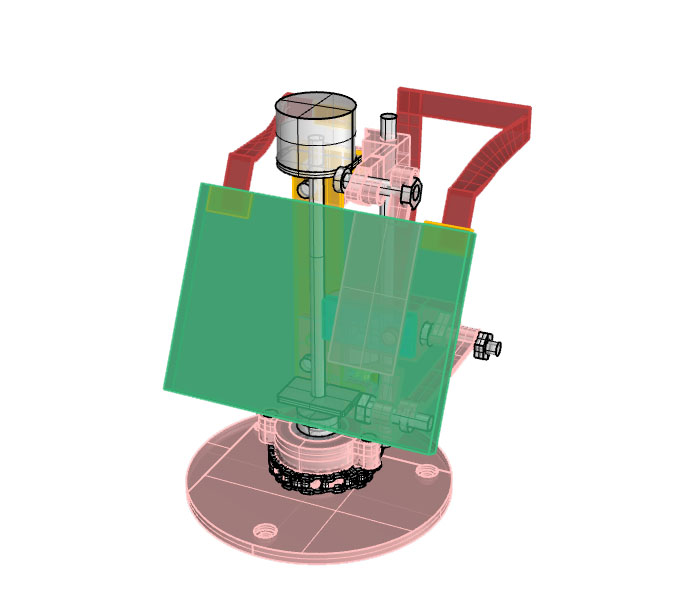
I’m doing a next design based on the observation that the motor is struggling to pull up the solar panel and that the weight could be repositioned closer to the center of gravity and rotation axis. It’s more sunflower like, and the lead screw is now exposed as in version one. Nicer balance in terms of the bending joints which now aren’t all on the same side. One of the three bearings is hidden so the emphasis is more on the two side ones now. Far more sturdy rotation mechanism for the solar panel so no more warping and bending hopefully. The arm will have to travel far less distance to change the angle of the solar panel also.
This experiment is interesting to me because it’s an attempt to move towards a more robust design while trying to keep it visually interesting and maintaining the attention to form.
I adapted it for a mirrored version of the linear drive and new lead screws (it wasn’t too hard to do). Now I have right and left handed machines:
This is interesting as it shows how easy or not it is to adapt to the repurposed CD drive mechanisms with the current design and how much variation can be created organically.
***
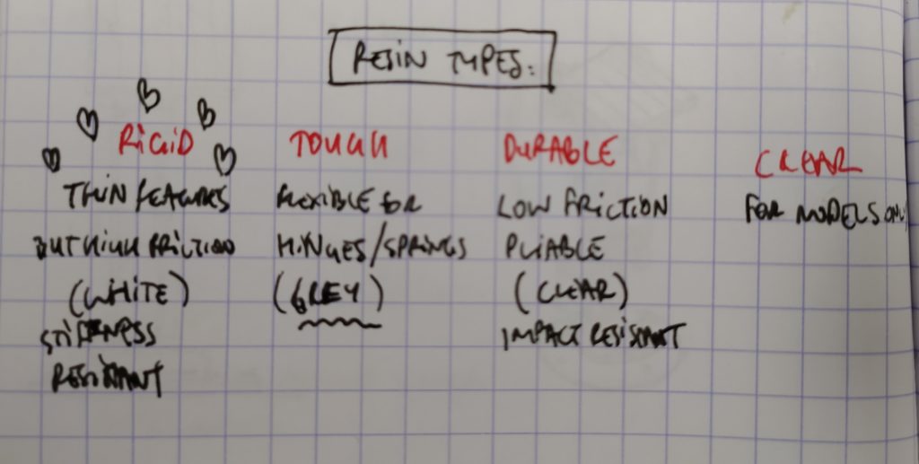
It looks like I should go with white Rigid resin and that I should use bushings for the sliding portions so no part of the print has friction.

These appear to be the key characteristics of the lead screw/nut setup.
****
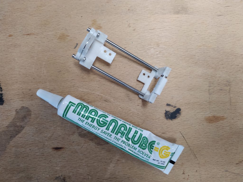
Adding some grease to the rails:
*****
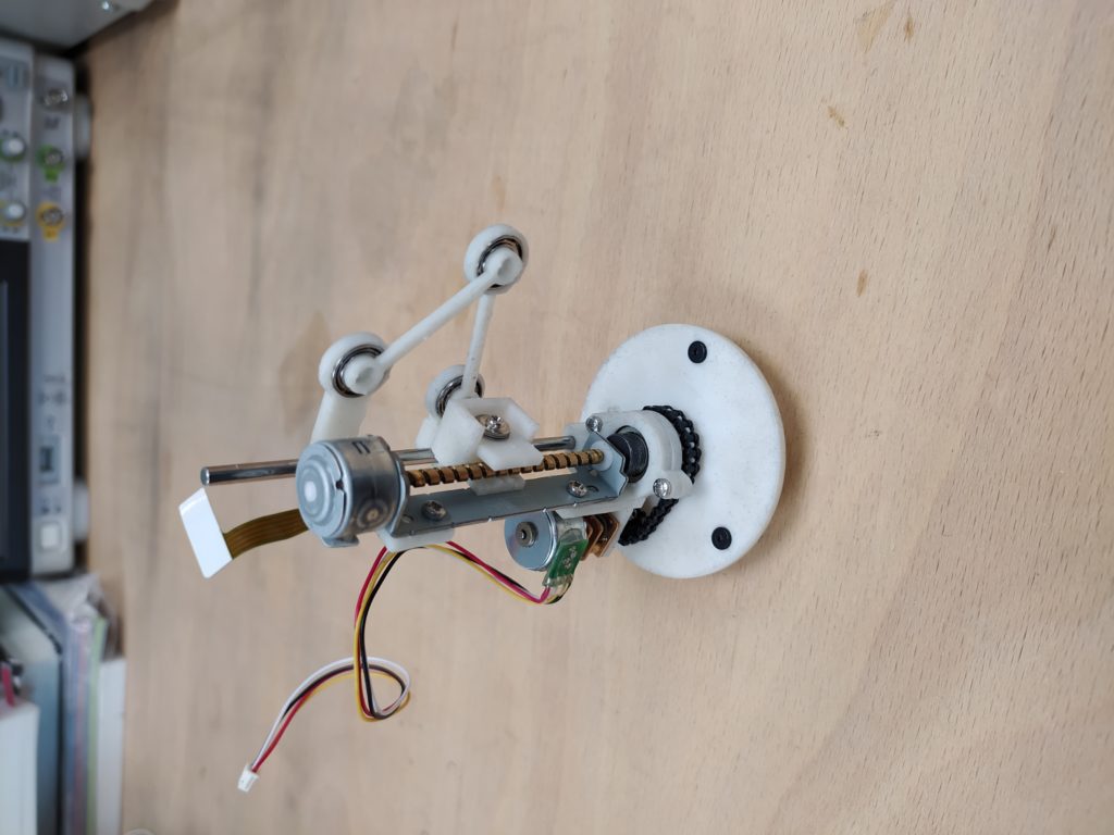
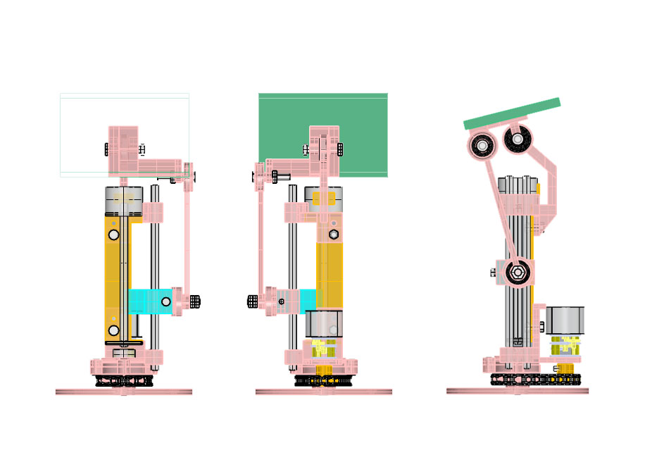
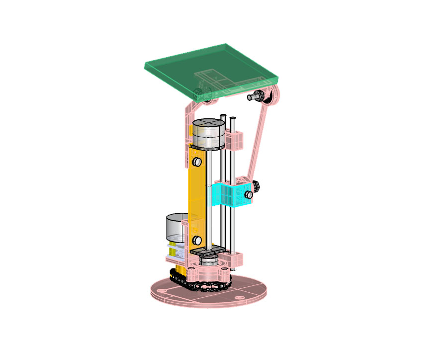
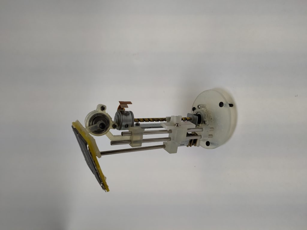
Here’s the tall version:
It has great tilt range.

It feels much taller and more slender. It also looks far more like a sunflower. It’s also lost its animate / cuteness quality that comes from being compact and now feels more like a machine. It does make more sense in terms of weight distribution, however.
It proves that the idea of adjusting for found CD drives works in principle.
V.4 ERRATA:
- The Durable resin is too flexible to make rigid longer parts. The whole assembly is flopping all over the place.
- I need to modify the central solar panel hinge – it’s not possible with the hardware I have to make it function properly. Because the tilt arm pulls from the side, it has a tendancy to tweak the central hinge. I could use the large bottom bearing up top?
****
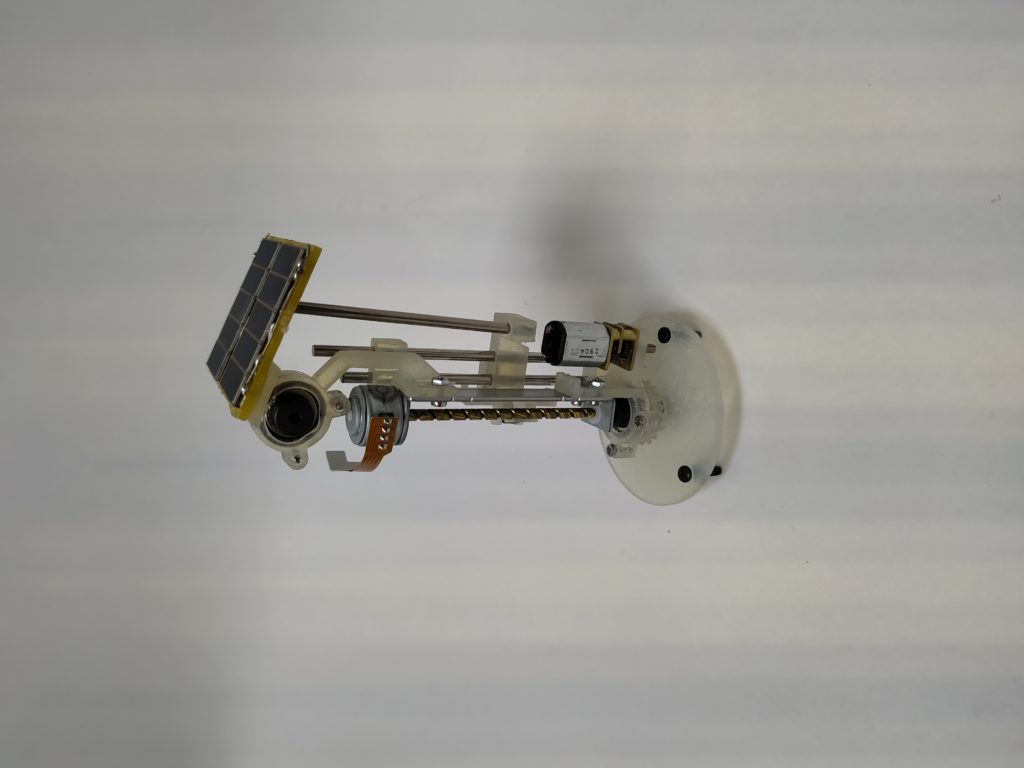
The new version features a pole that pushes up to tilt the solar panel, and lets the panel rotate down when it descends. This means fewer bearings and maybe less strain on the linear actuator stepper motor:
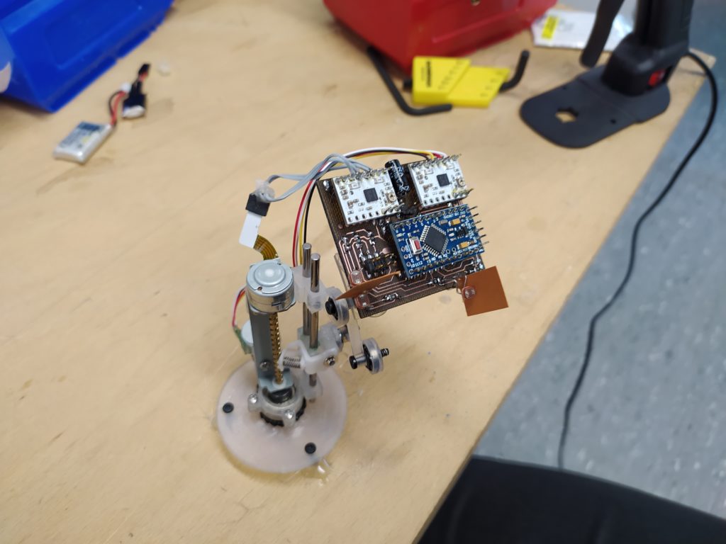
I’ve redesigned the control board. It now has a nicer spacing between the motor driver out pins and doesn’t have any other wires nearby to get in the way of these pins. It also has the motor driver sleep pins connected to the microchip, and can drive two steppers instead of one stepper and one DC motor as with the previous version. It also has more noise attenuating caps:
![]()
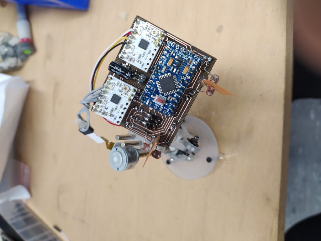
I am also considering using an Arduino Nano with DRV8834s and a mini lithium ion just to get this prototype running!
This works but it’s very heavy with the battery packs. I may need to glue the bearings in place or work with a more robust design for this phase.
I’m using the StepperDriver Arduino library and this is what my loop looks like:
if (analogRead(A0)-analogRead(A1)>threshold)
{
stepperTop.move(-MOTOR_STEPS*MICROSTEPS);
}
if (analogRead(A1)-analogRead(A0)>threshold)
{
stepperTop.move(MOTOR_STEPS*MICROSTEPS);
}
if (analogRead(A2)-analogRead(A3)>threshold)
{
stepperBottom.move(-MOTOR_STEPS*MICROSTEPS);
}
if (analogRead(A3)-analogRead(A2)>threshold)
{
stepperBottom.move(MOTOR_STEPS*MICROSTEPS);
}
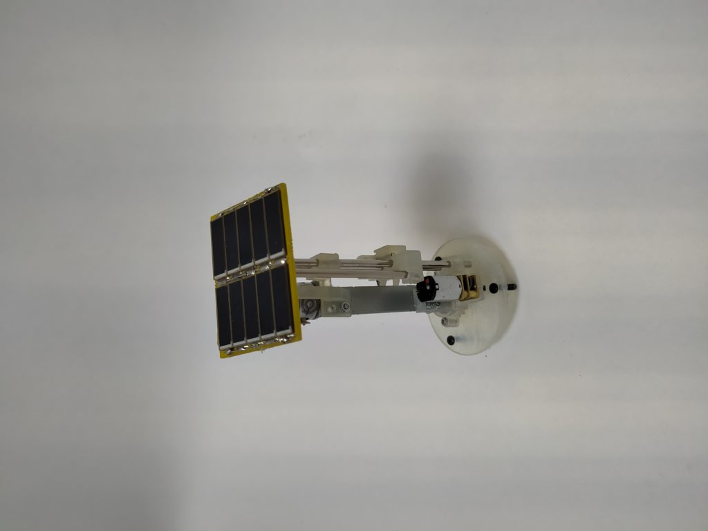
And here’s the new print:
****
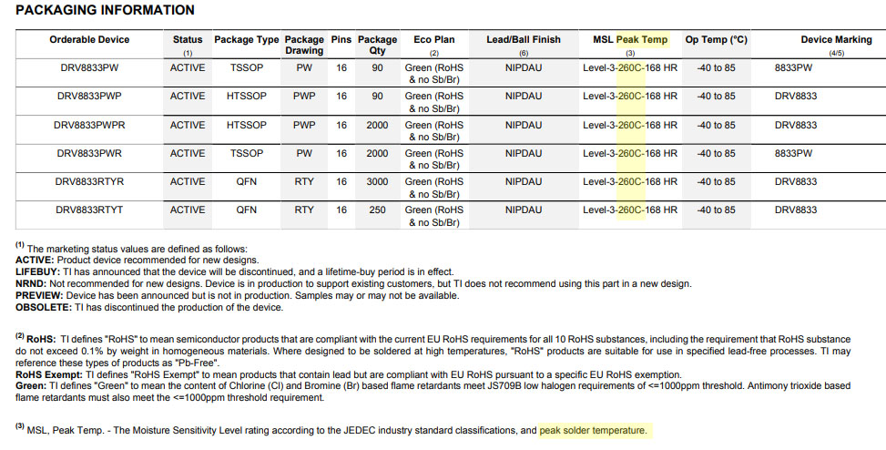
Just discovered why I may have been having issues with the DRV8833s…Their max soldering temperature is 260C, I have been using 300C!
****
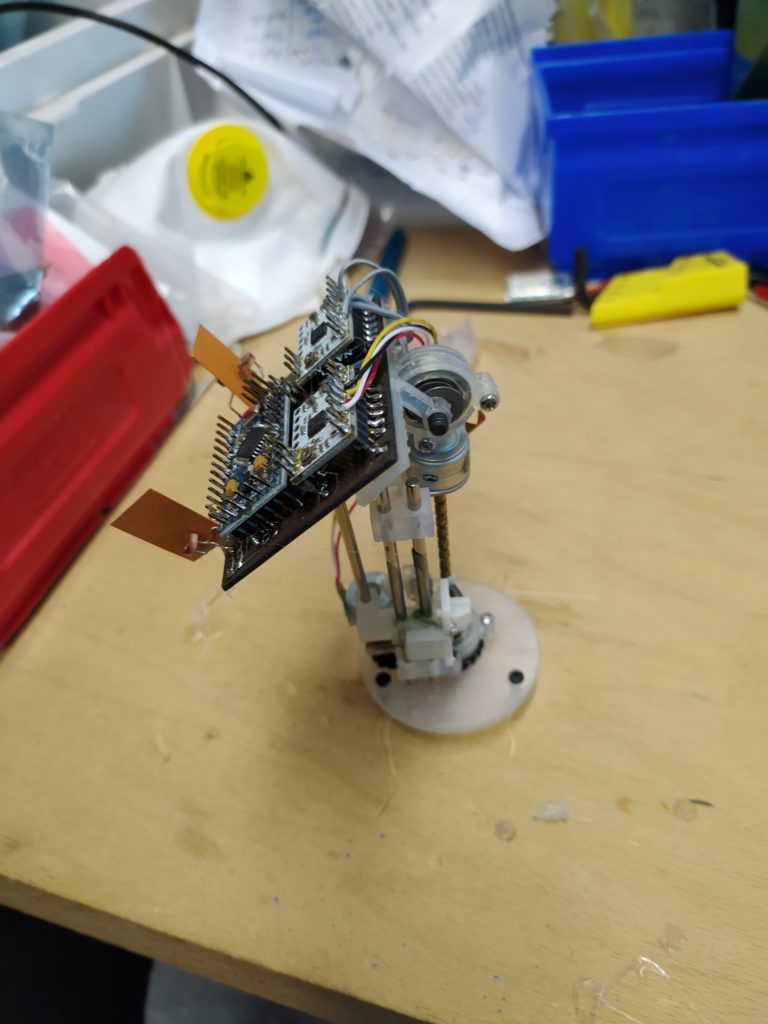
I tried to get a full prototype running with the Arduino breakoutboard version but it’s surprisingly heavy and both attempts were unsuccessful. The second:
Without the weight of the circuit board everything is fine however:
I think I may have to admit that this thing is too janky to work beyond as a quick video.
*****
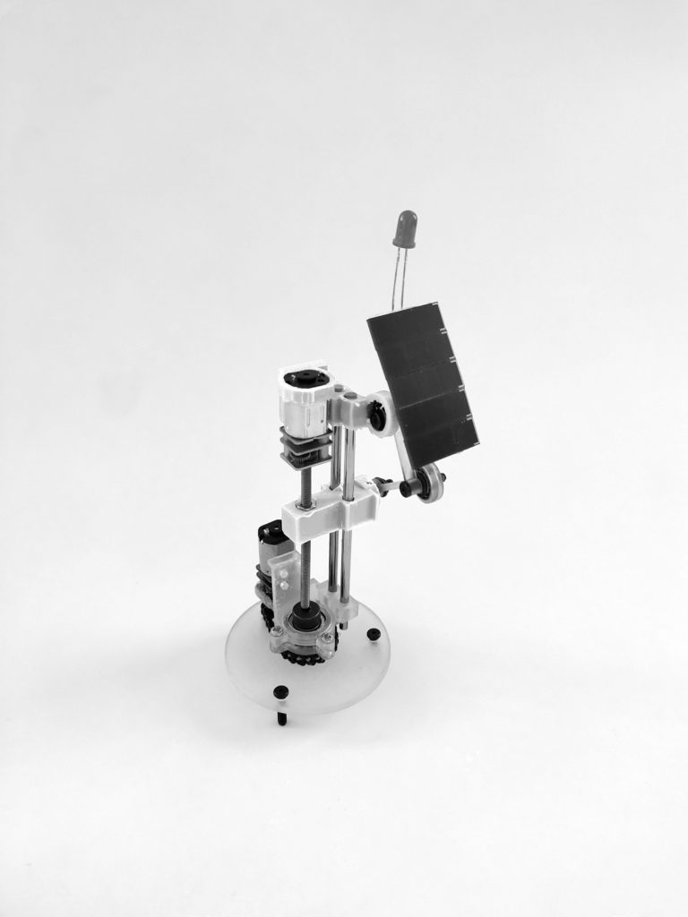
Meanwhile I’m working on a DC prototype of the more complex 2DOF design:
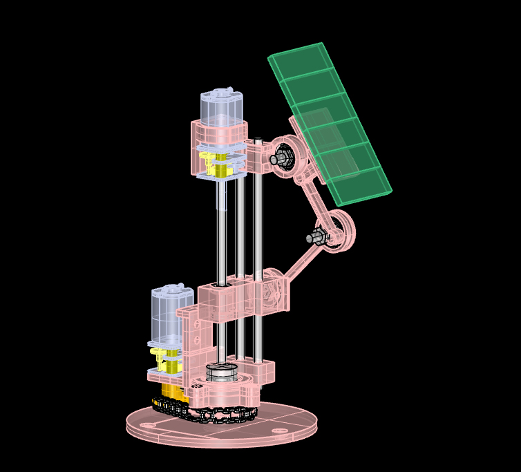
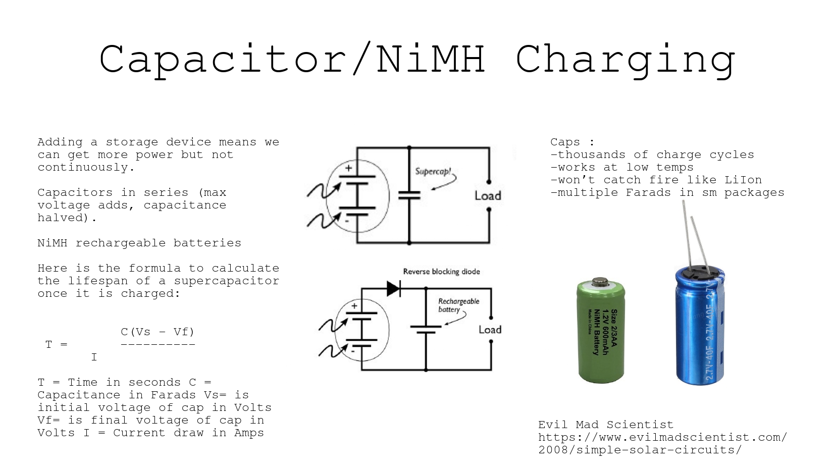
The idea here is to have 2 1DOF solar engine circuits + a dark activated pummer circuit. The machine would then spend its days searching for the sun and charging up a bigger capacitor to then blink at night like a lighthouse. I’m not sure if I should make the blinking synchronise with other nearby blinkers using this circuit:
https://www.instructables.com/Synchronizing-Fireflies/
One DC motor (controlling the tilt) is so slow it’s barely noticable at all while the other one swings the machine round dramatically. The design has less magic than the servo version but is far easier to control and has no issues with the weight of the solar panels.