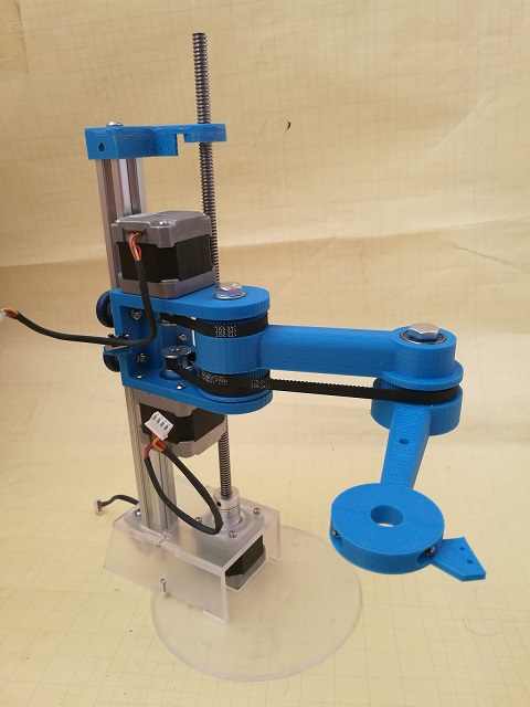
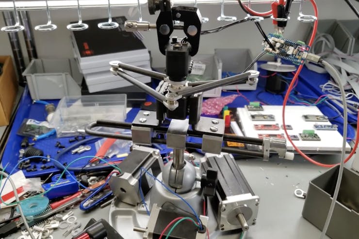
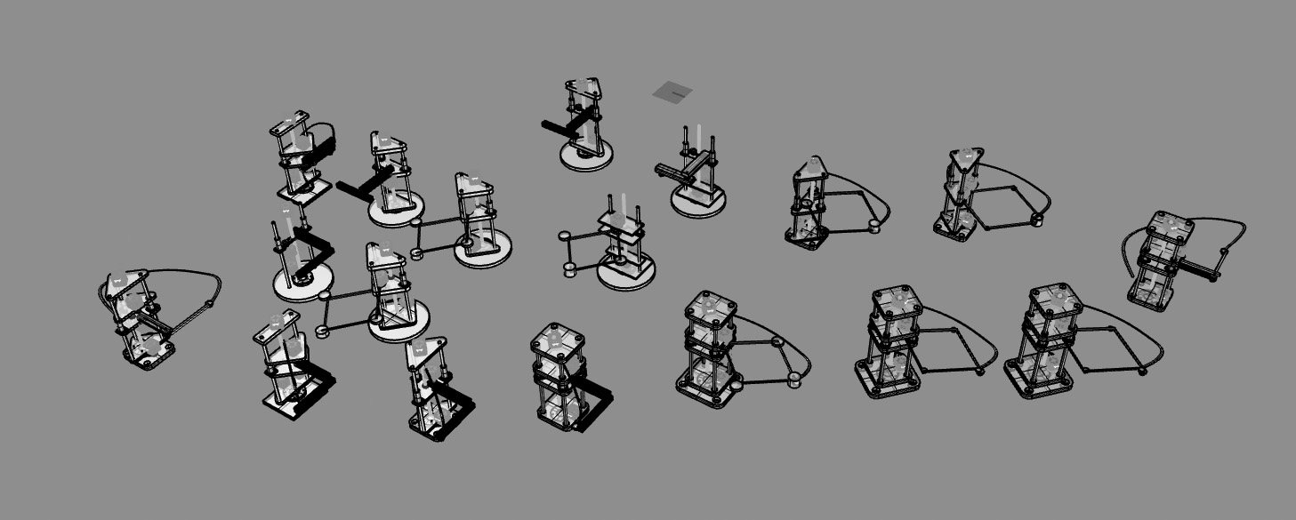
Here is the final product:

After the relative success of the foam cutting machine, I would like to build a medium-sized robot arm which can actually be a useful tool in the lab and not just a toy.
The main questions appear to be: how to increase the torque of the stepper motors? Should we make a classic robot arm or a Selective Compliance Assembly Robot Arm SCARA? Should the parts be 3D printed or CNC milled (or a combo)? and, Do I already have the parts necessary or do I need to order them in which case how much should I order?
**********
Stepper torque options:
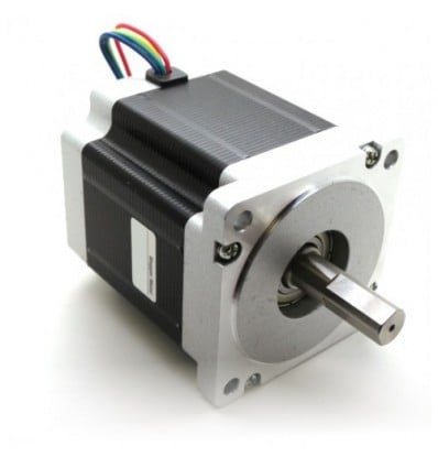
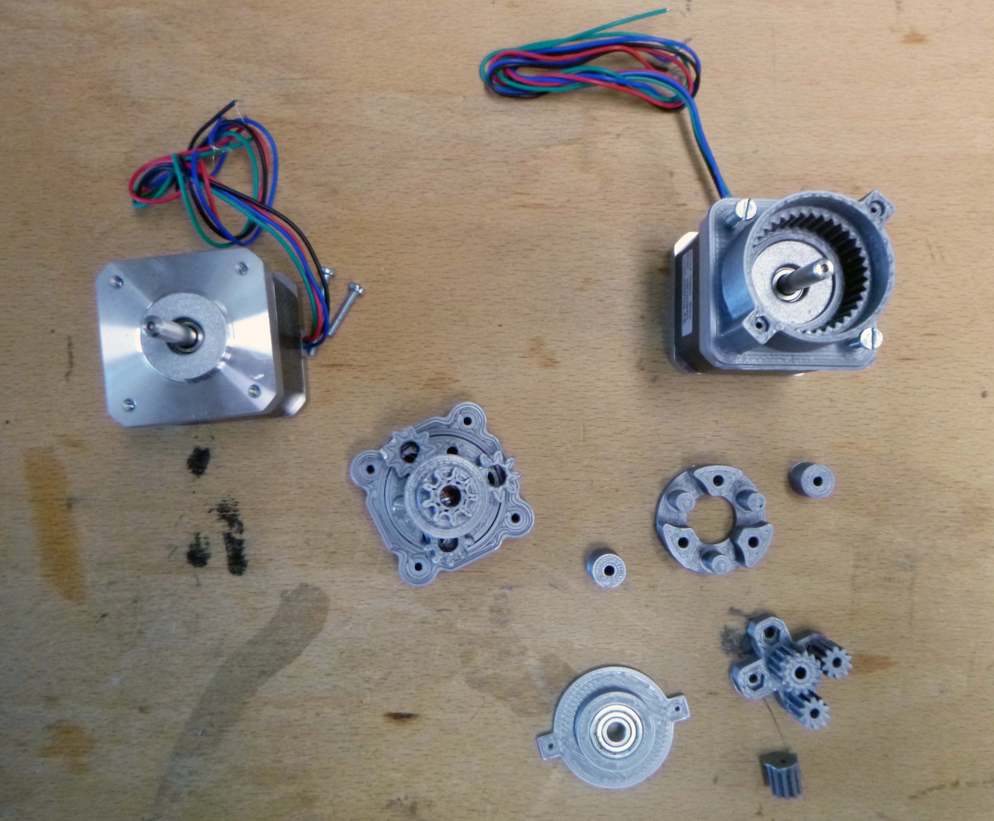
1. Use our super beefy stepper motors. Unfortunately, none of the other hardware (like belt sprockets) fit the diameters of the shafts.
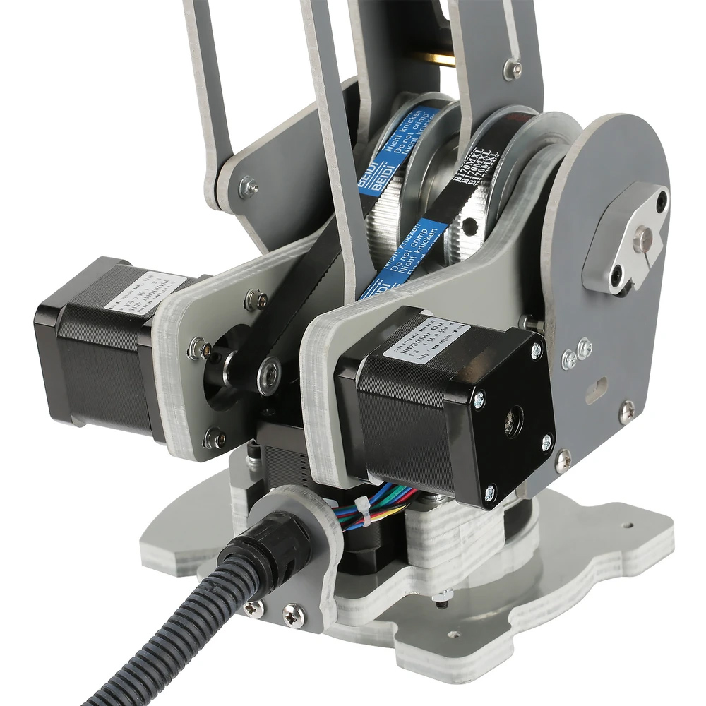
2. 3D print a planetary gear or buy one:
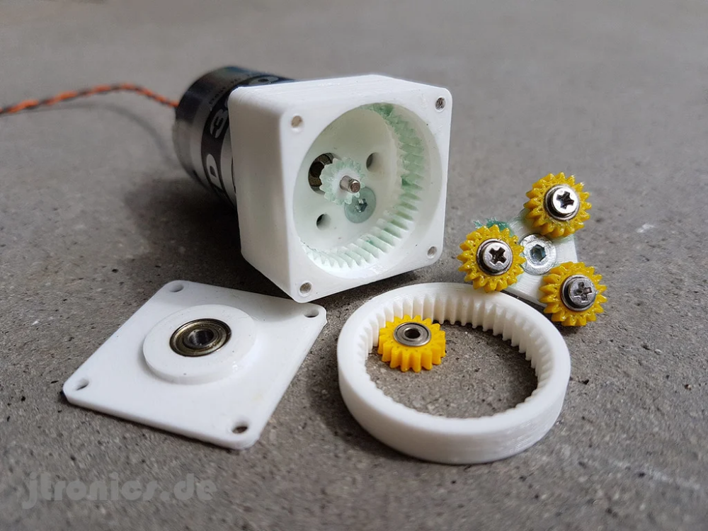
![]()
(but these make the front of the stepper bulky and a bit ungainly)
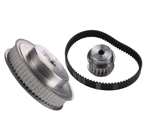
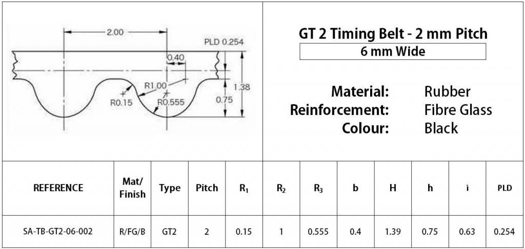
3. Get a large timing belt pully with a short belt drive: (unfortunately we don’t have anything like this lying around the lab).
4. 3D print a large gear to turn directly with the stepper:

A different concept that involves a motors not all at the base:

**********
SCARA vs. Conventional robot arm.


#SCARAs fold up easily and are faster for certain tasks than conventional robot arms.


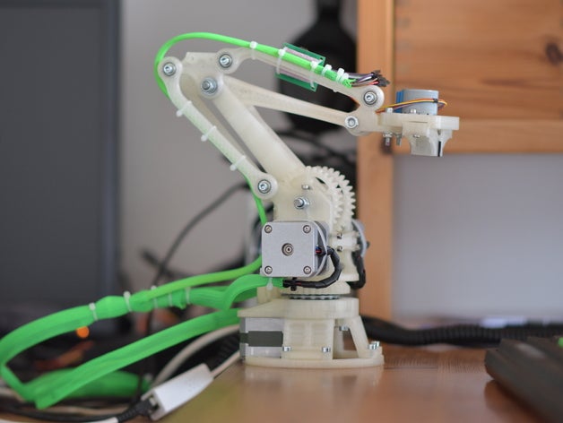
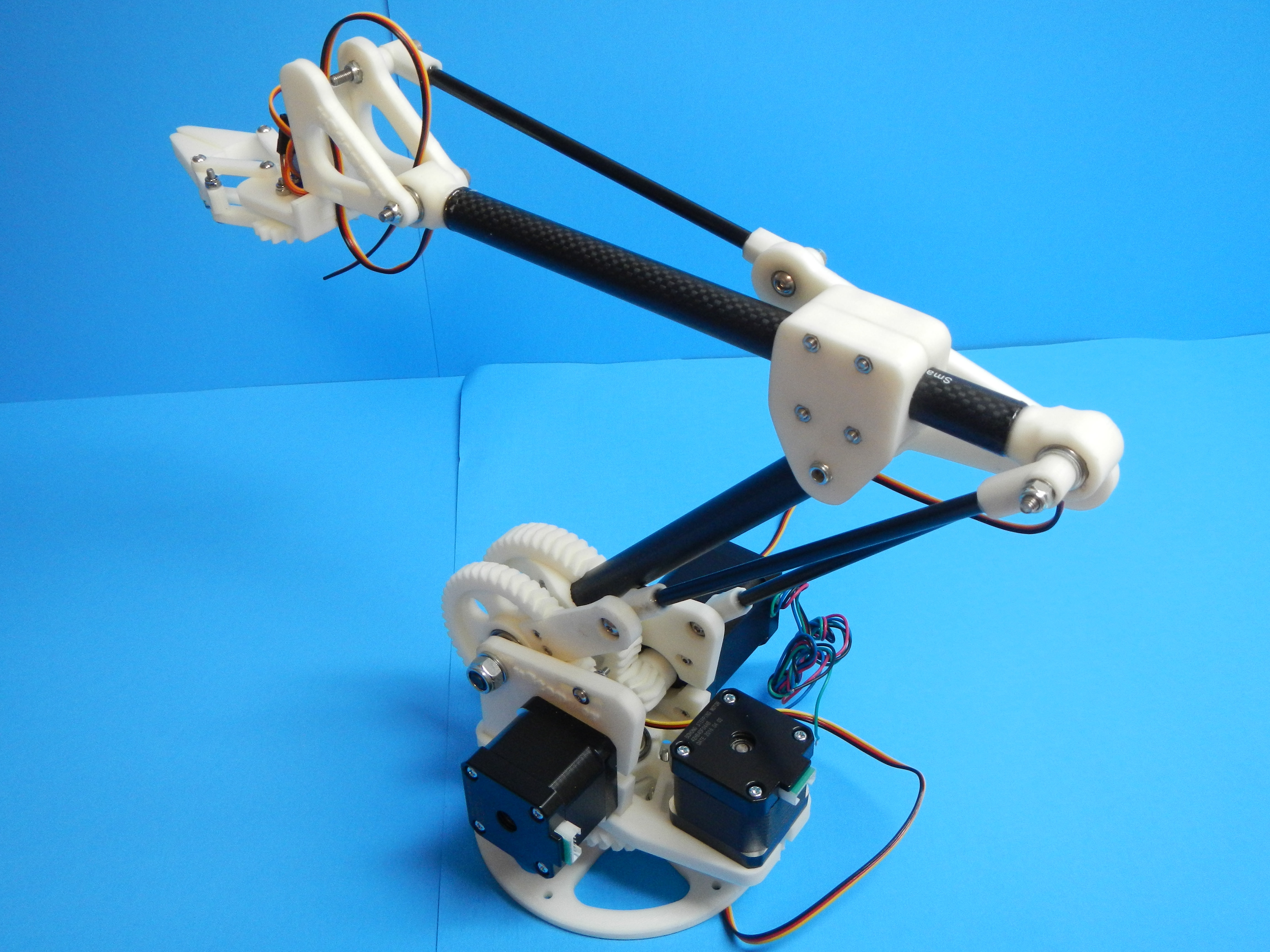
But there are some neat conventional robot arm designs out there too:
*******
CNC milling vs. 3D printing:
CNC milling some parts (like the large gears) seems possible:

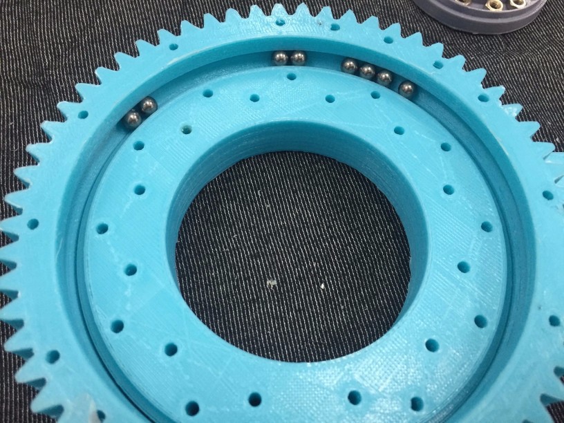
But I also need either to buy a large bearing or to make my own bearing…Unless I make a geared slew bearing:

Here’s a cool guide on designing gears: https://lcamtuf.coredump.cx/gcnc/ch6/
Some DIY slew bearings:


***********
Robot background information: http://www.societyofrobots.com/robot_arm_tutorial.shtml
Cool tutorial includes info about DOF, calculating torque for each joint (fewest joints possible with shortest lever arms the better): http://www.societyofrobots.com/robot_arm_calculator.shtml
Some simple arm linkage ideas:


**********
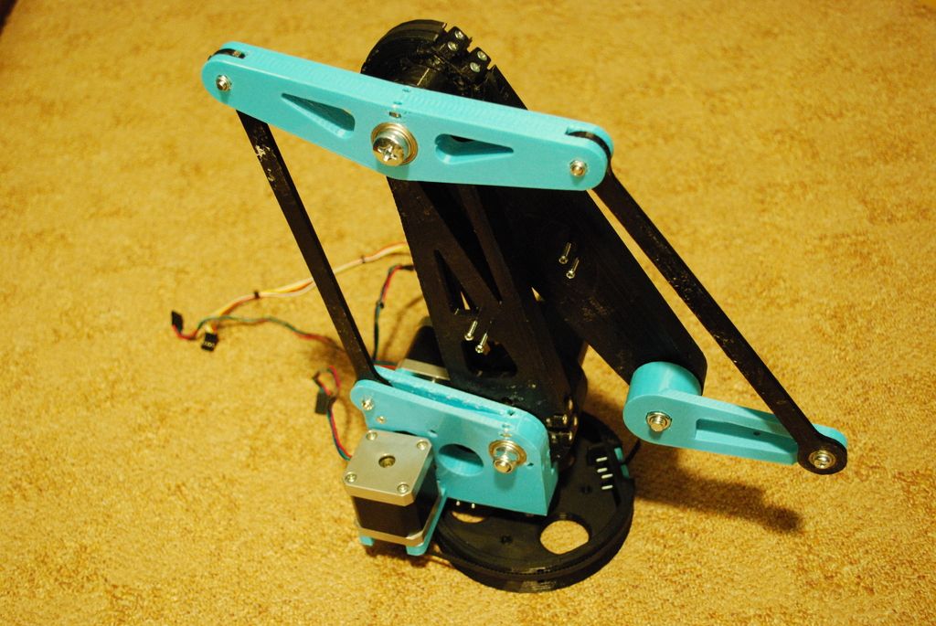
And these Five-bar linkage machines (aka Parallel SCARA robots), they appear to be known for being super fast:
https://en.wikipedia.org/wiki/Five-bar_linkage

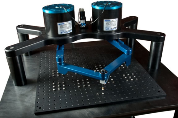
**********
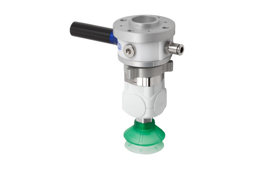
For the end effector I think either air pressure or electromagnet:
************
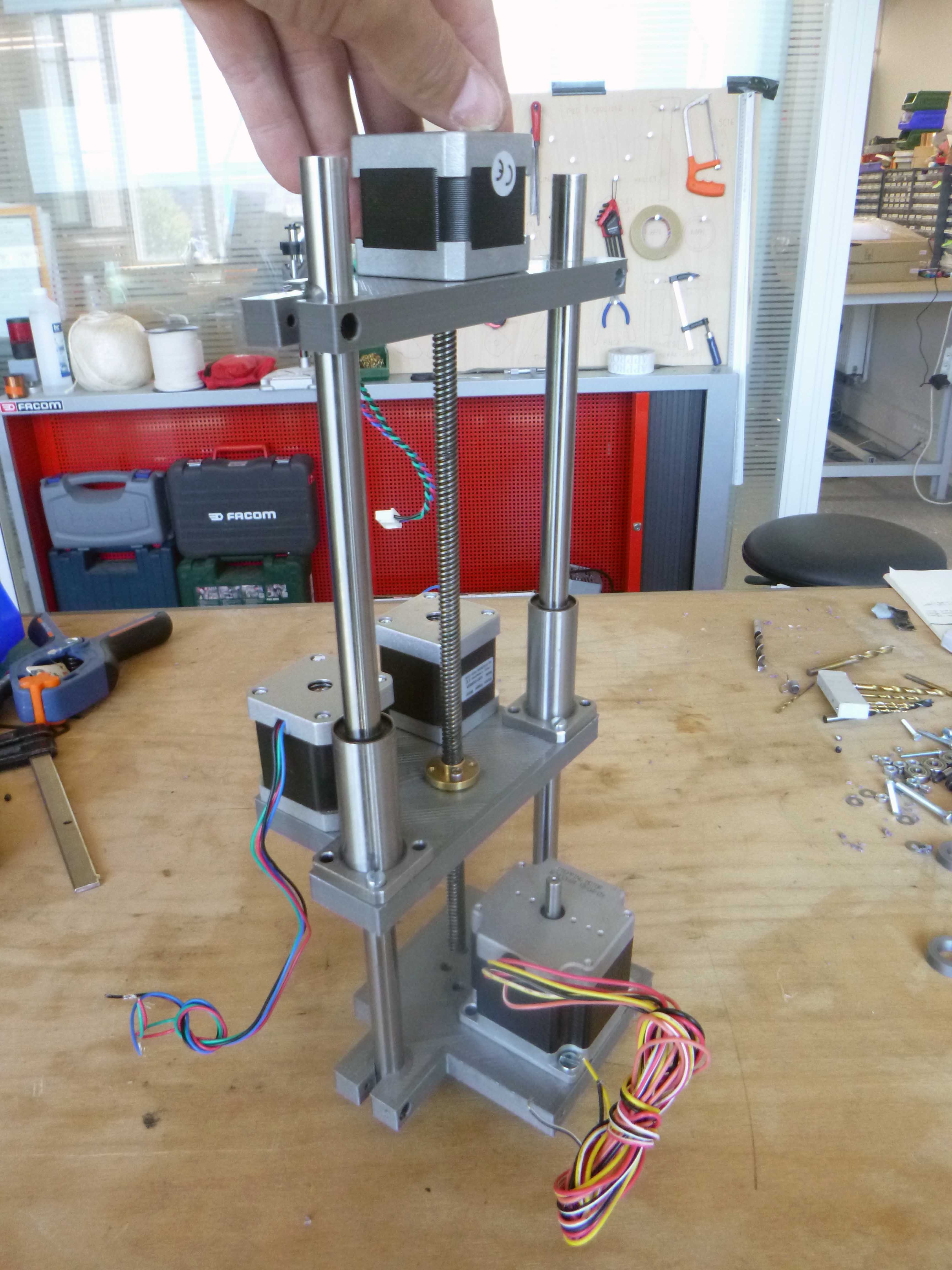
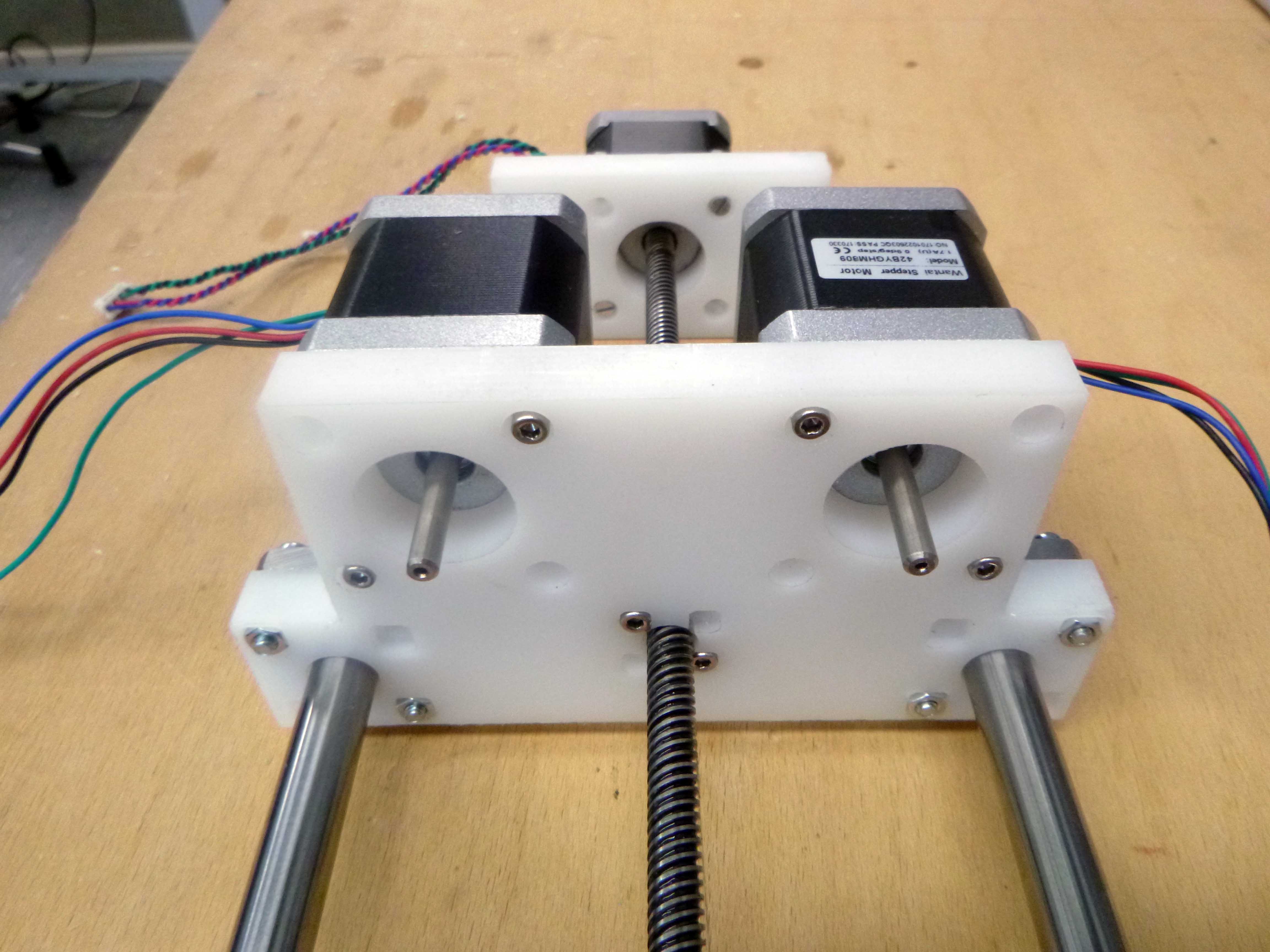
Some early models:
With only two rails (I’m not sure if this is sufficiently stable or not as many designs have 3 or even 4 rail):
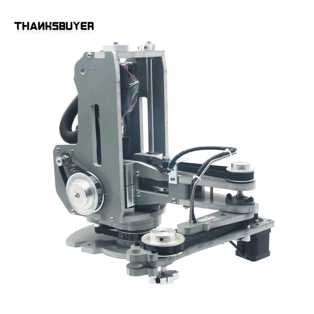
Similar but with a larger motor at the bottom and less ugly mounting plate.
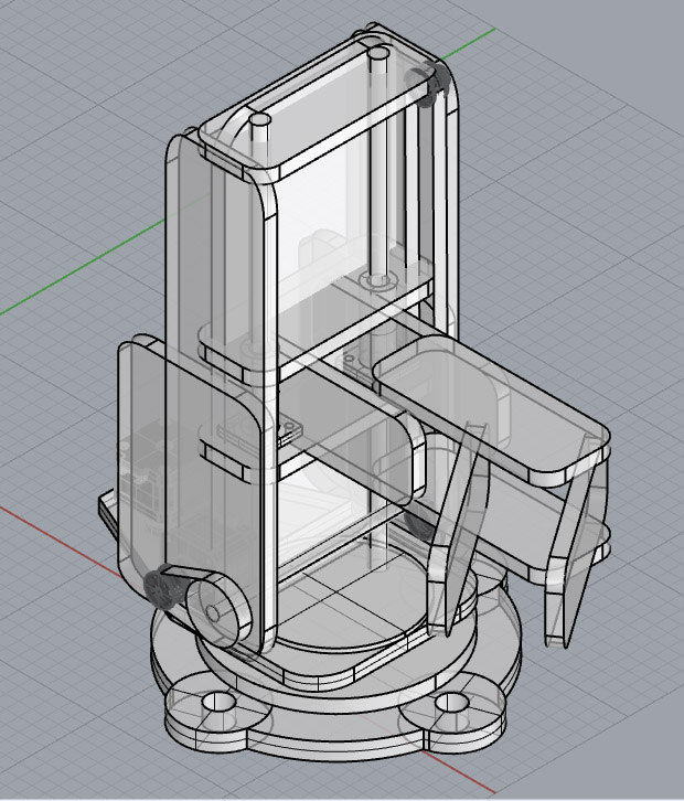
A completely different SCARA design, I like the silhouette but it would involve tons of cut planar material that would need to slide into together and we might not have everything on hand to make this either:
Quick attempts at 3D printing planetary gears:
https://www.thingiverse.com/thing:2114390
https://www.thingiverse.com/thing:3231908
(interesting belt option here: https://www.thingiverse.com/thing:2911407)
Using the 0.8 nozzle was not ideal and none of the pieces fit properly. I would love to try this as a cnc cut project but I think it would be highly technical and difficult and at the end would end up in a tiny box. (I’m going for medium scale machines at the moment not tiny intricate things).
We have 12mm HDPE in white and blue in the lab, I’m going to first 3D print then mill it.
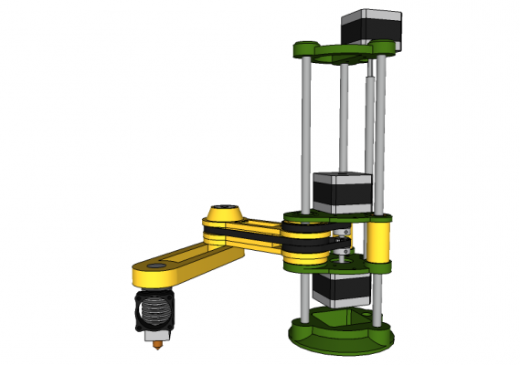
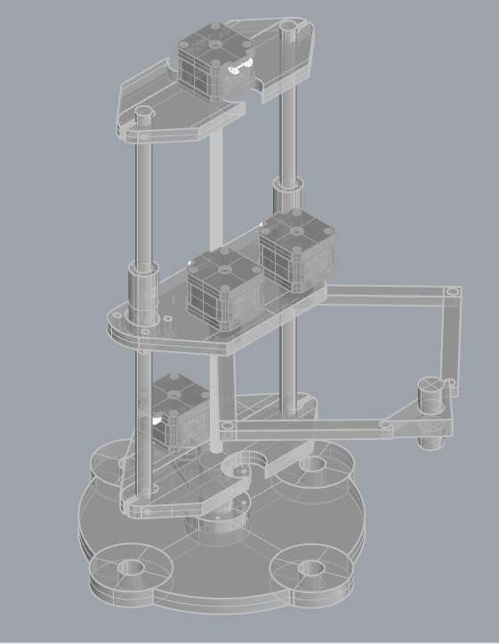
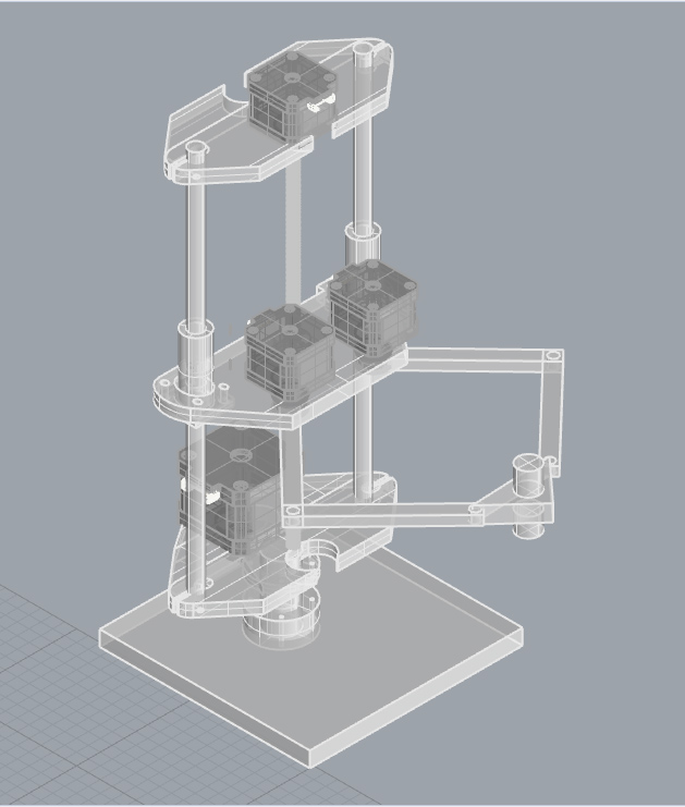
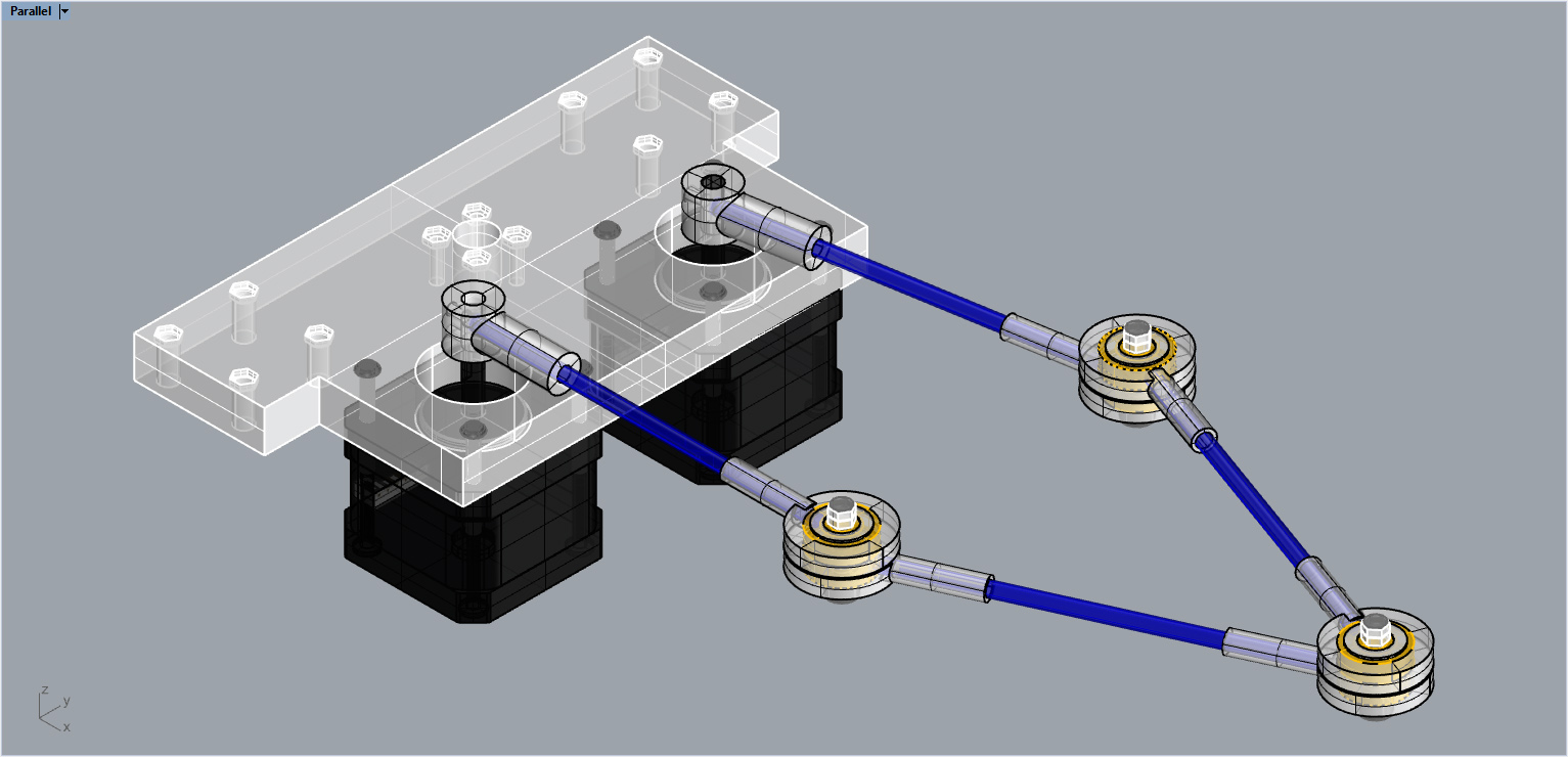
I’ve come to a compromise with the design. It will give me the opportunity to design with a Nema 23 a complex peice (geared slew bearing), to work for the first time with a 5 linkage parallel robot design, to CNC mill HDPE for a more robust machine, but also builds on the syringe pump linear actuator and the foam cutter designs. Most importantly, I have all the components I need to build the full prototype already in the lab.
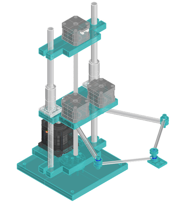
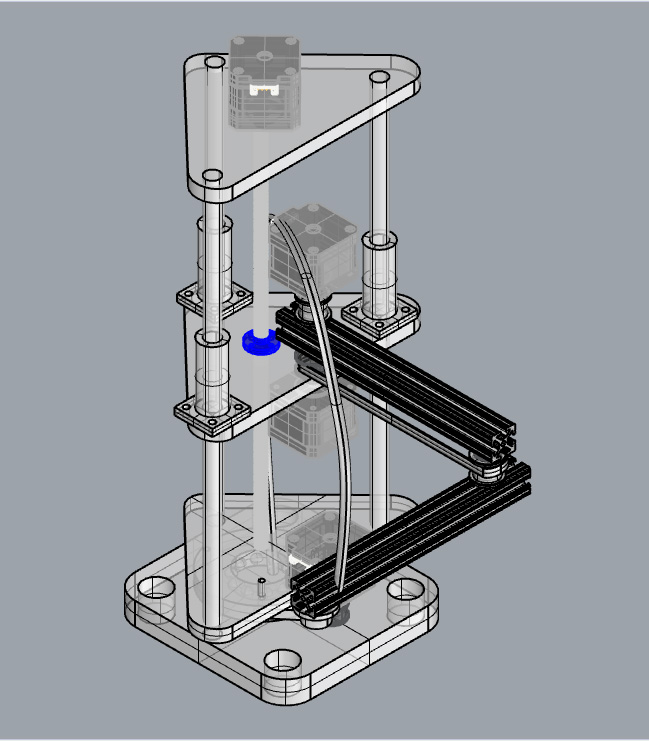
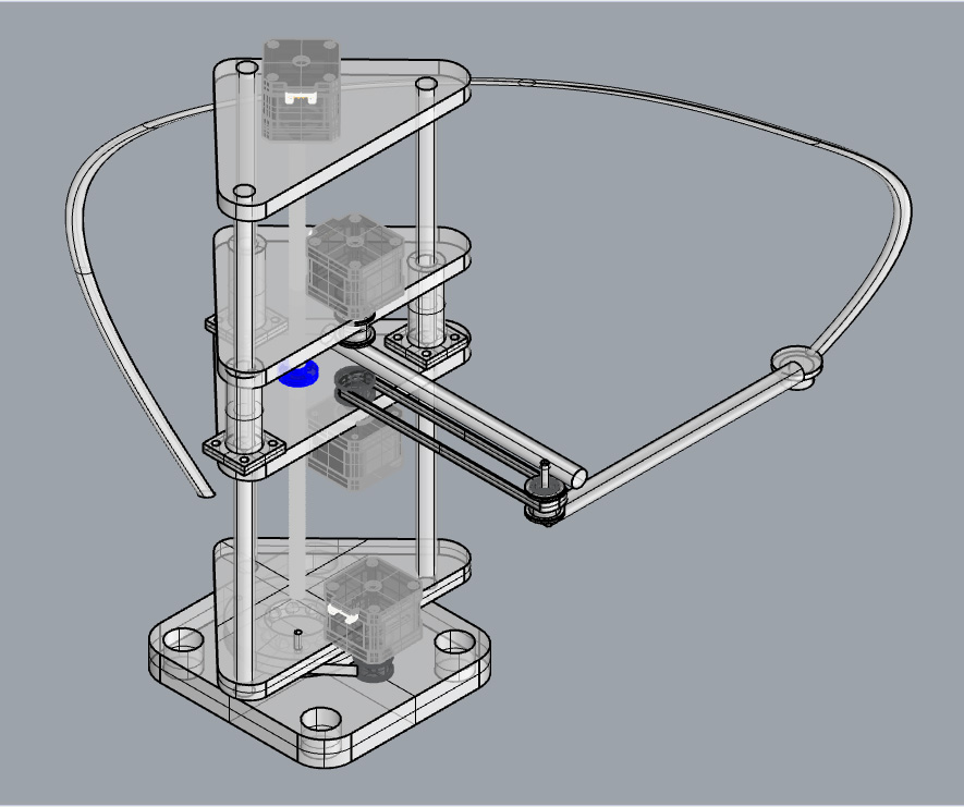
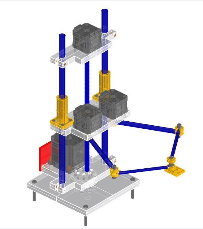
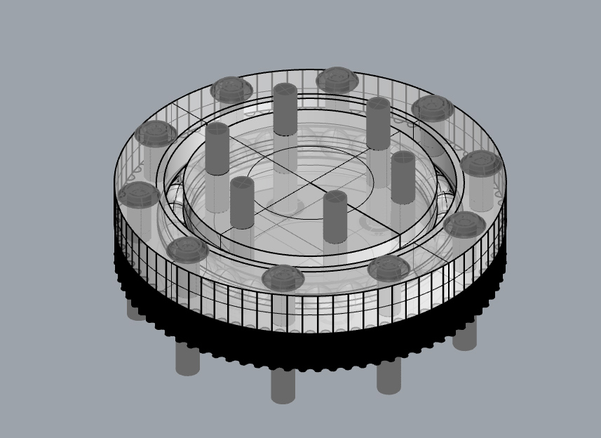
I added hardware to this model to make sure everything makes sense:
*********
Developement of the geared slew bearing:
Outlined this drawing in Rhino and then applied it to a circle:
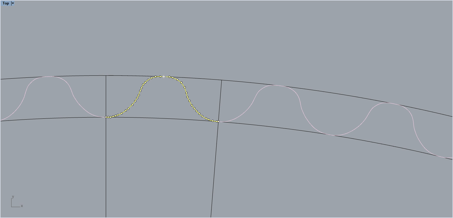
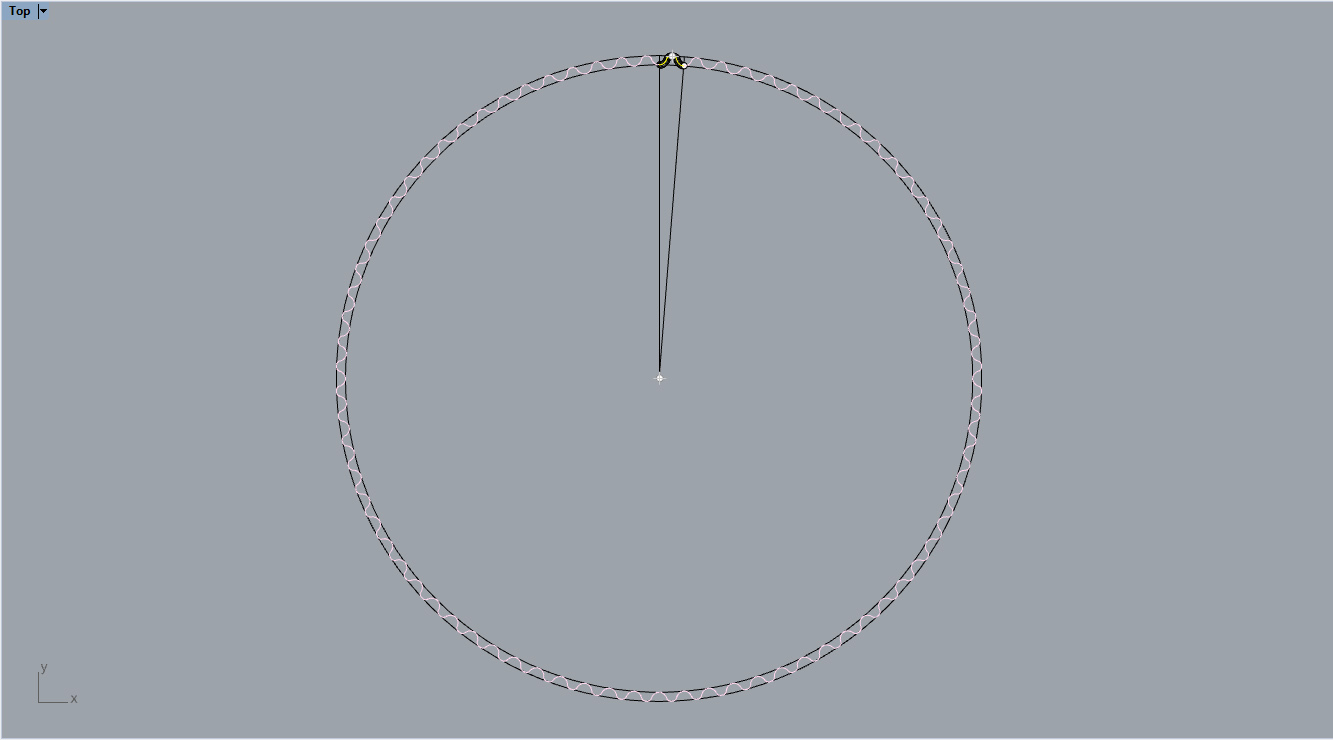
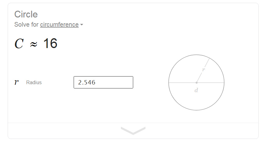
To make everything fit (increments of 2mm) I changed the size slightly of the gear:
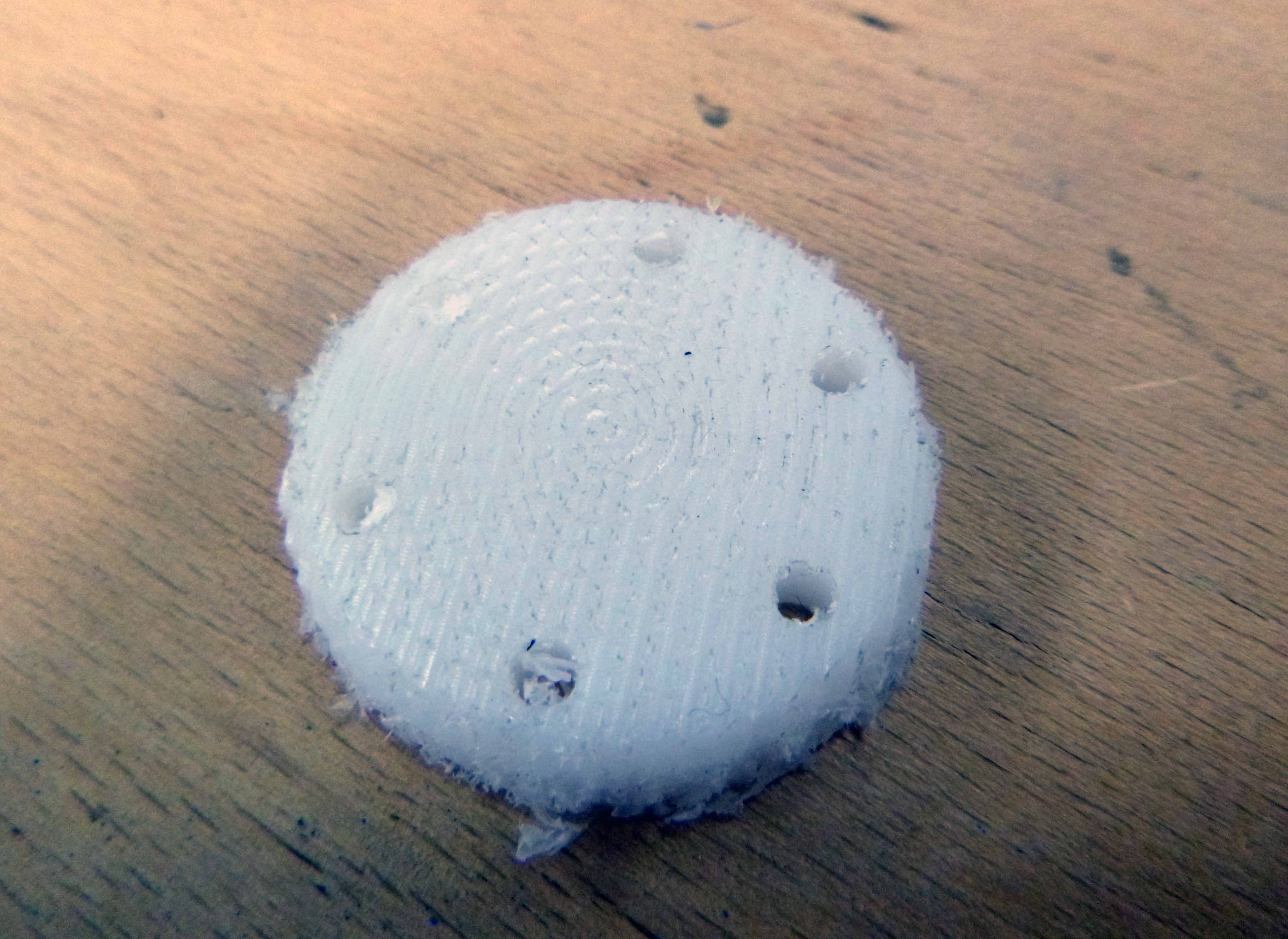
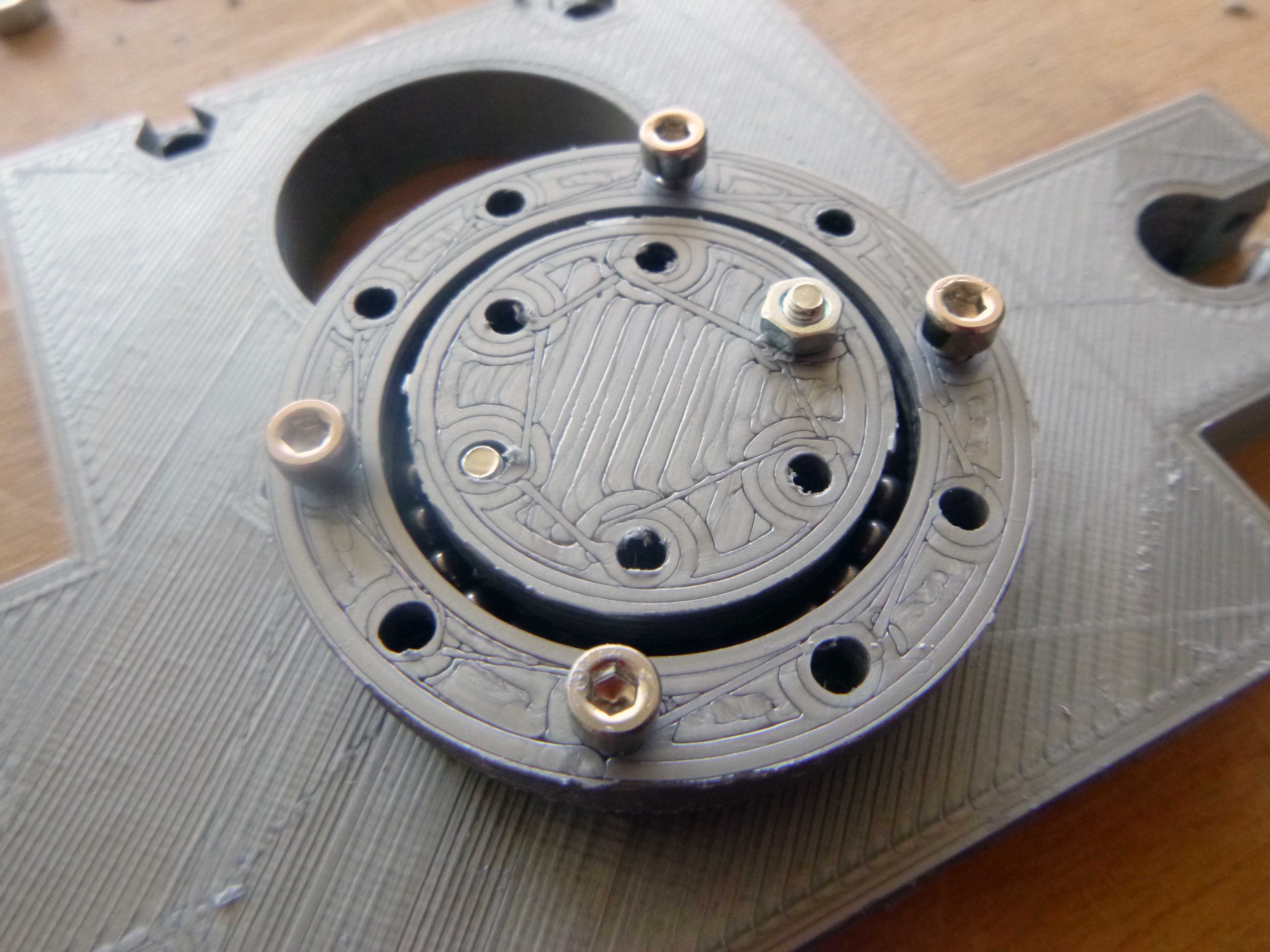
Here is the first prototype:
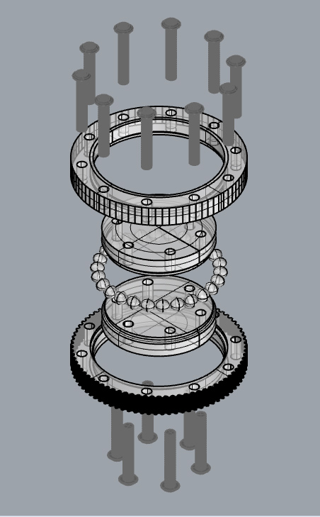
Here is a section showing the bearings cut through and how two layers of 6mm HDPE should come together to make the bearing. After assembling we’ll see if .1mm was too much spacing between the bearing and the walls, and also if there need to be two rows of 4mm bearings.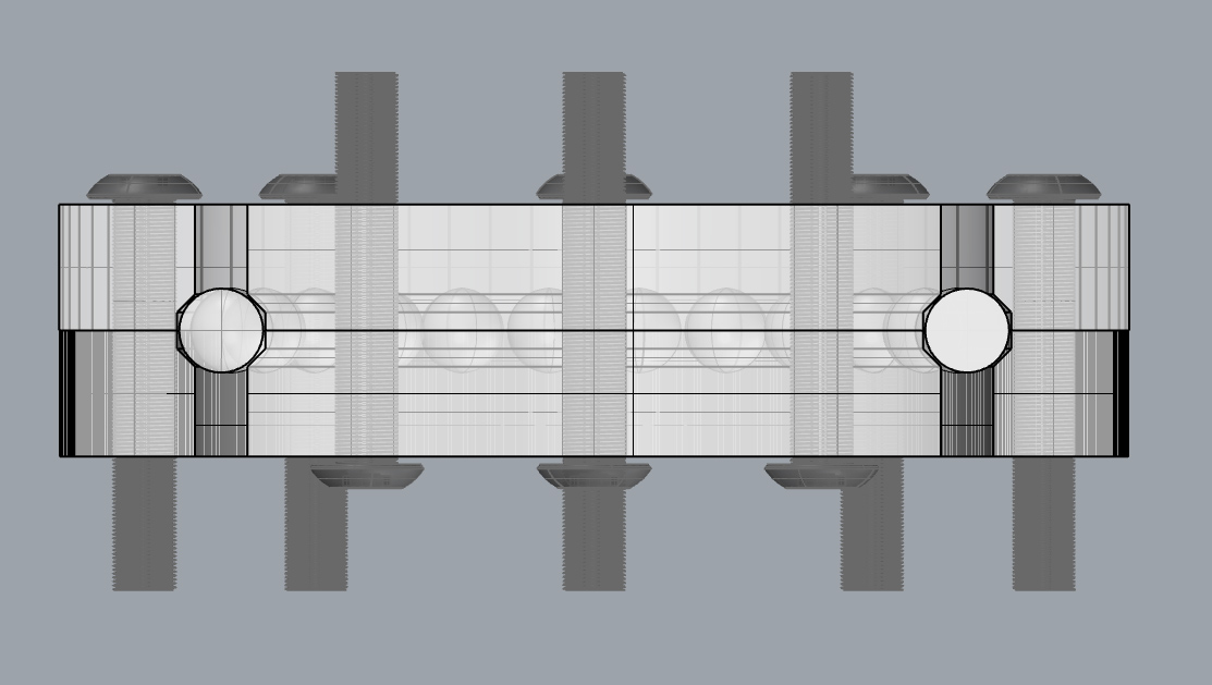
*******
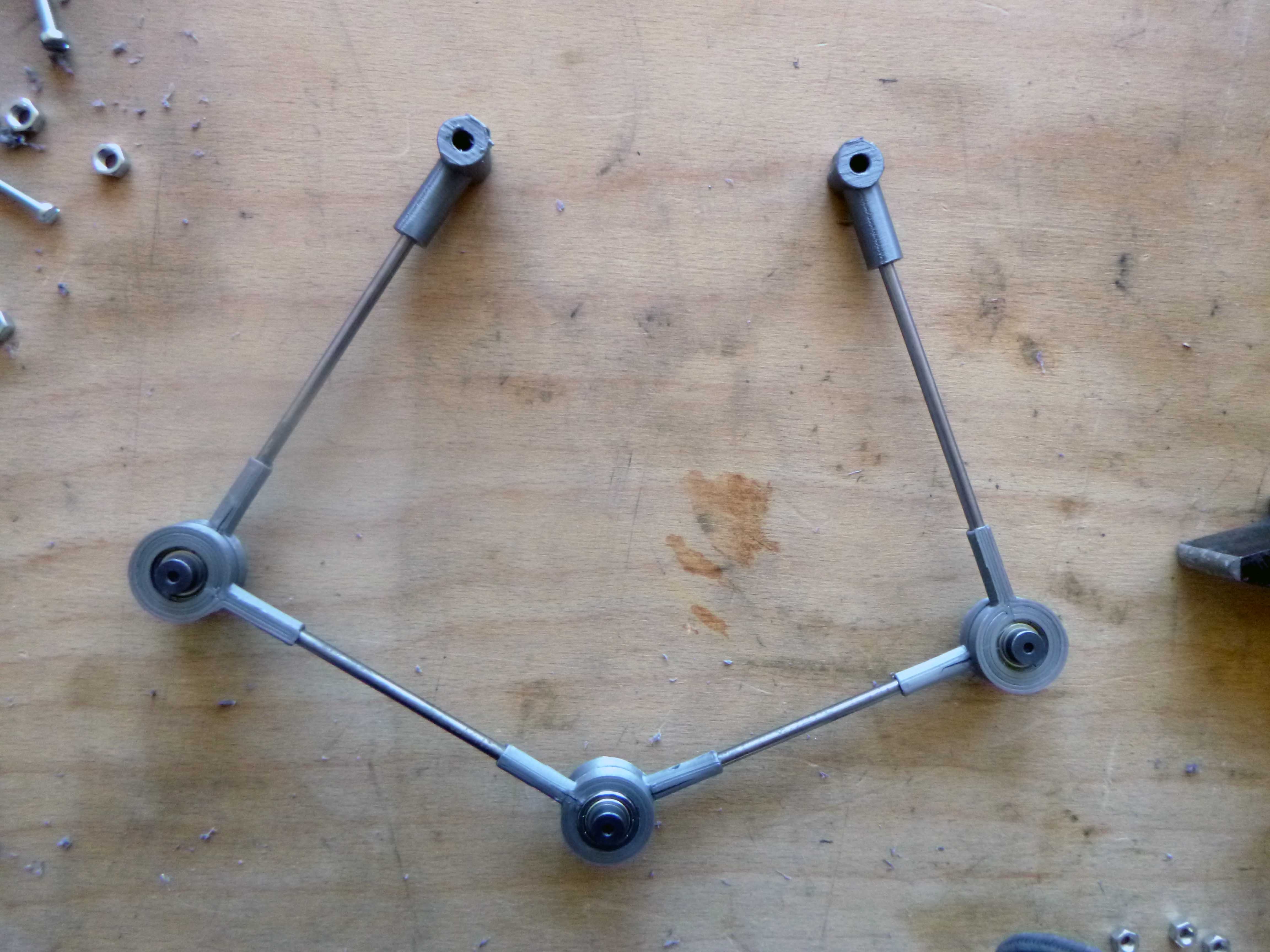
Here are the 5 bar parallel robot 3D printed parts (view from underneath):
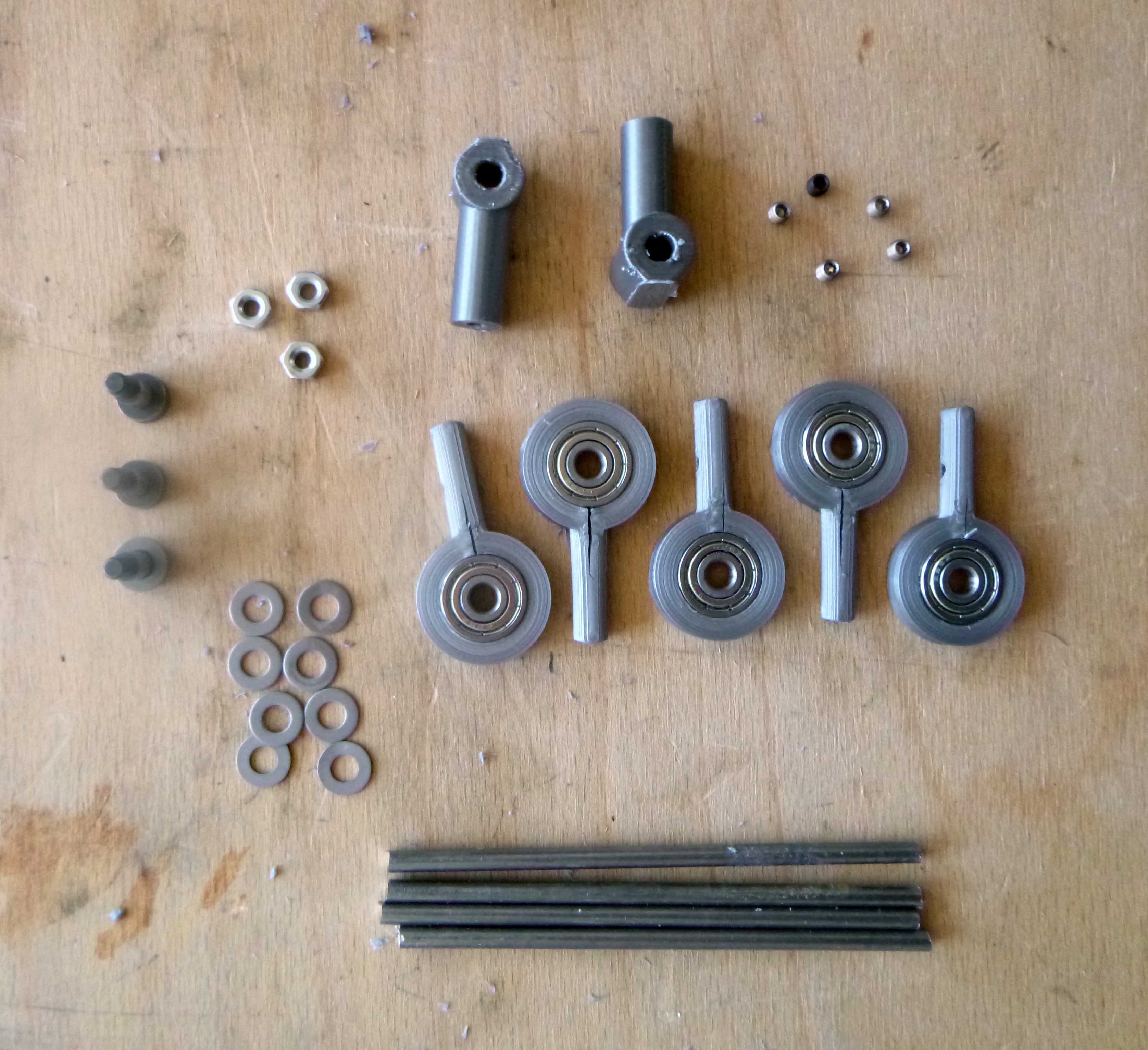
A combination of nuts, washers, 16mm bearings and socket shoulder bolts:
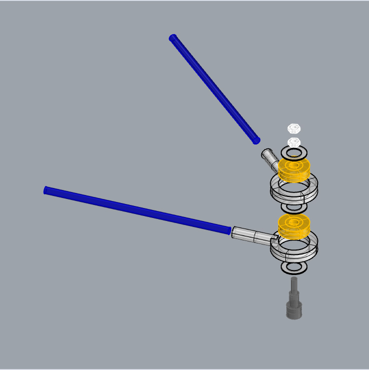
There is an offset in order to make everything work on the stepper motor shafts:
*****
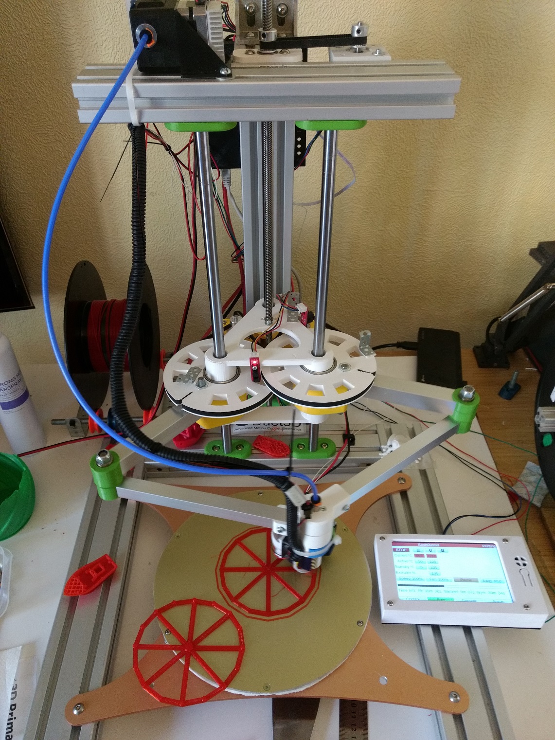
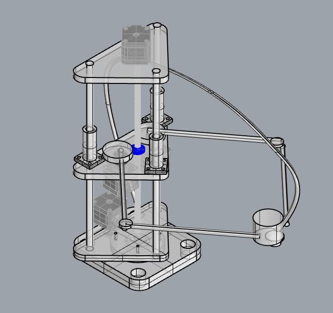
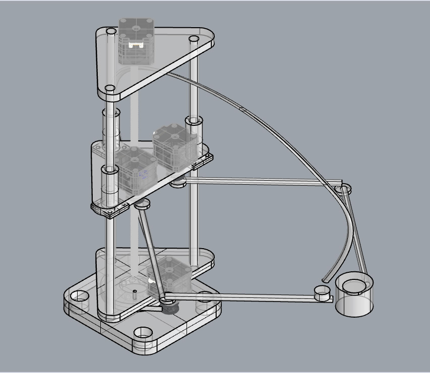
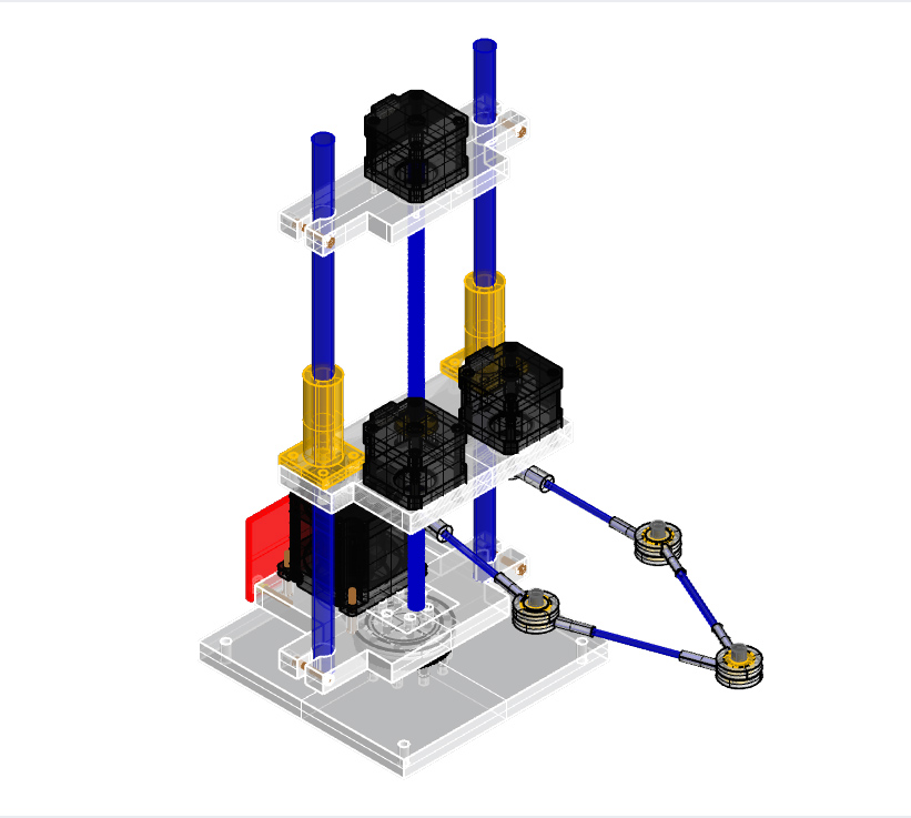
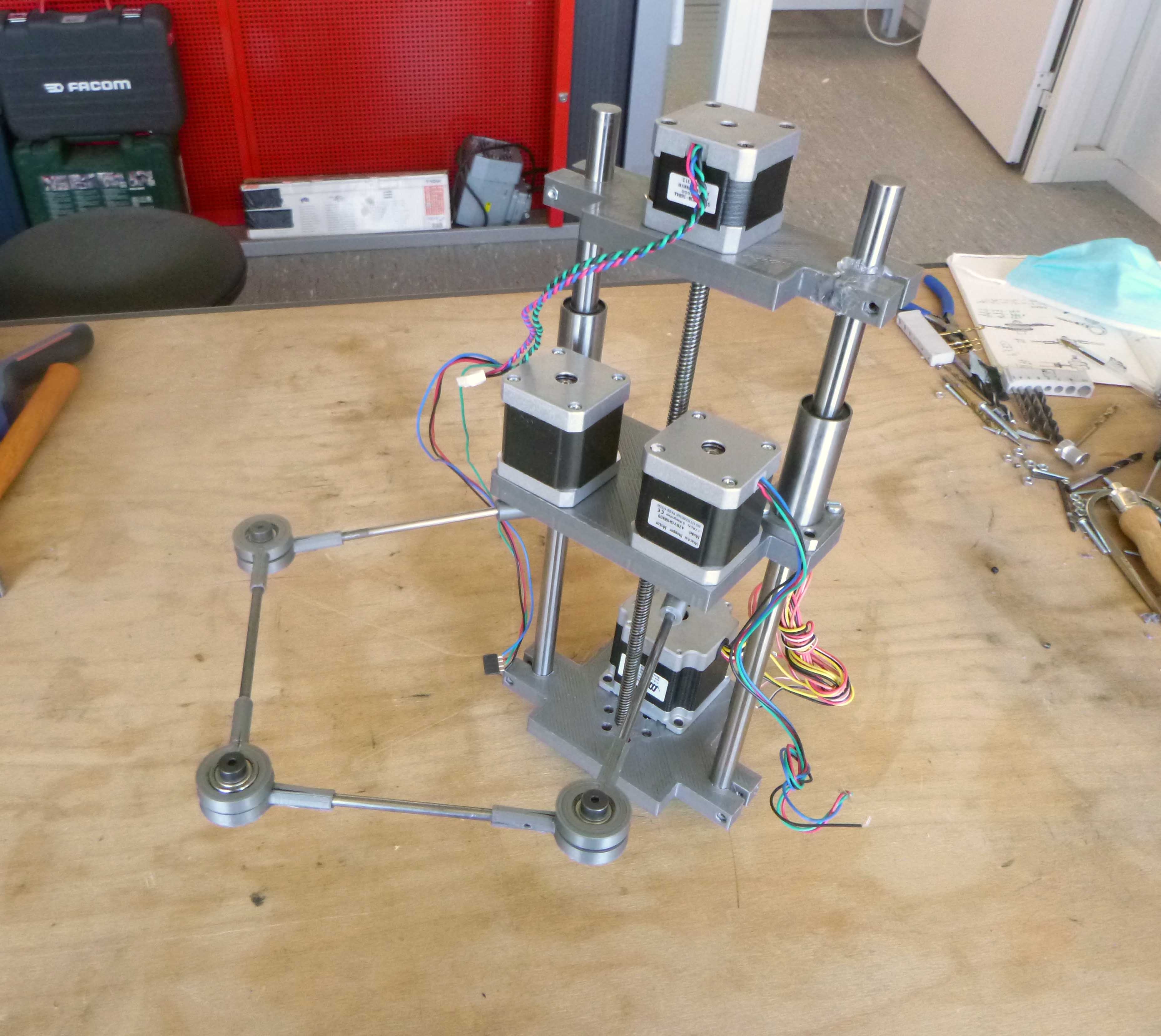
With the final additions here is the final machine:
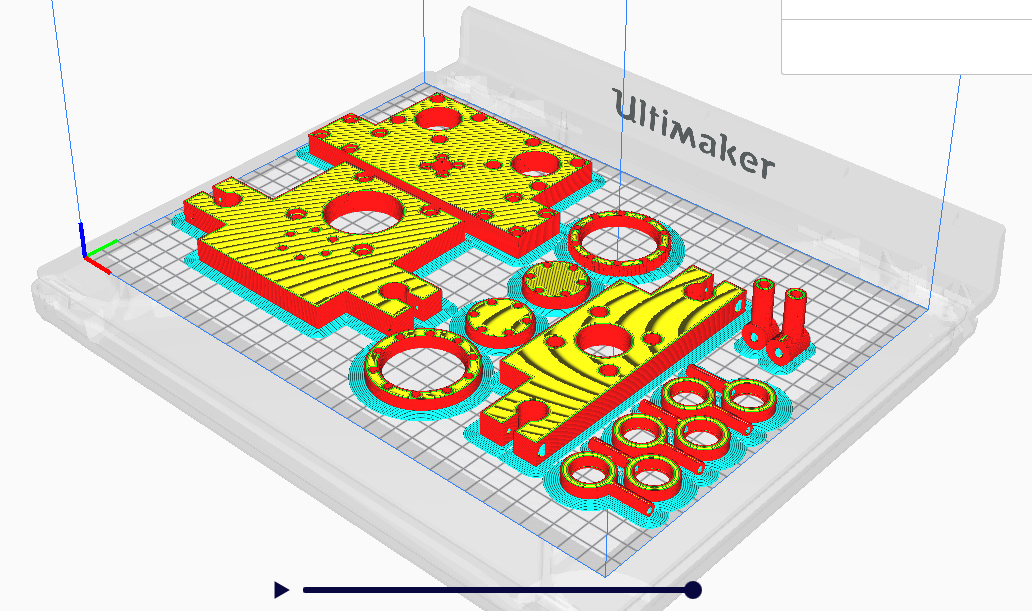
Here’s the 3D print file with all the parts:
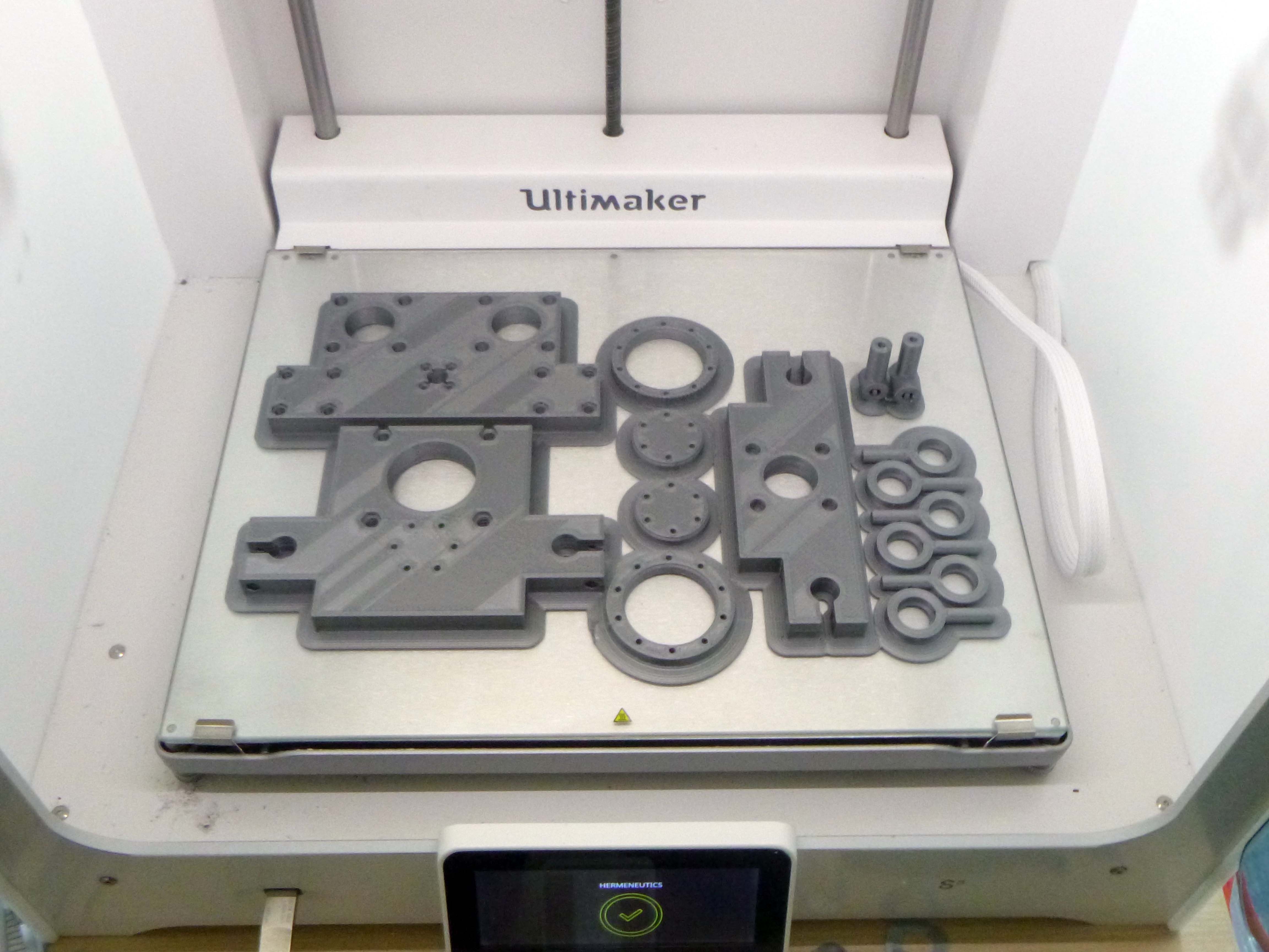
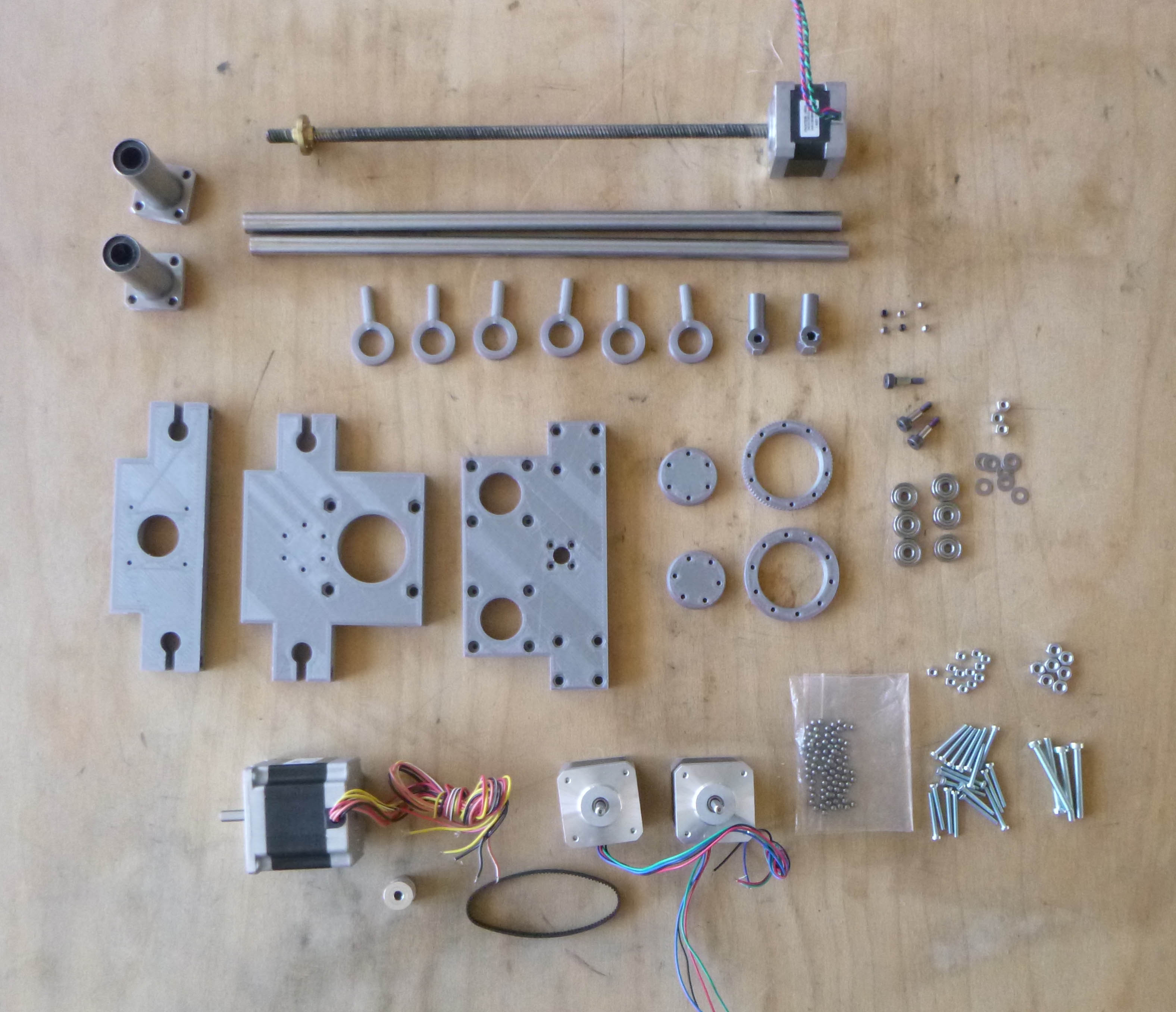
Here is the kit of parts (minus the parallel arm rods):
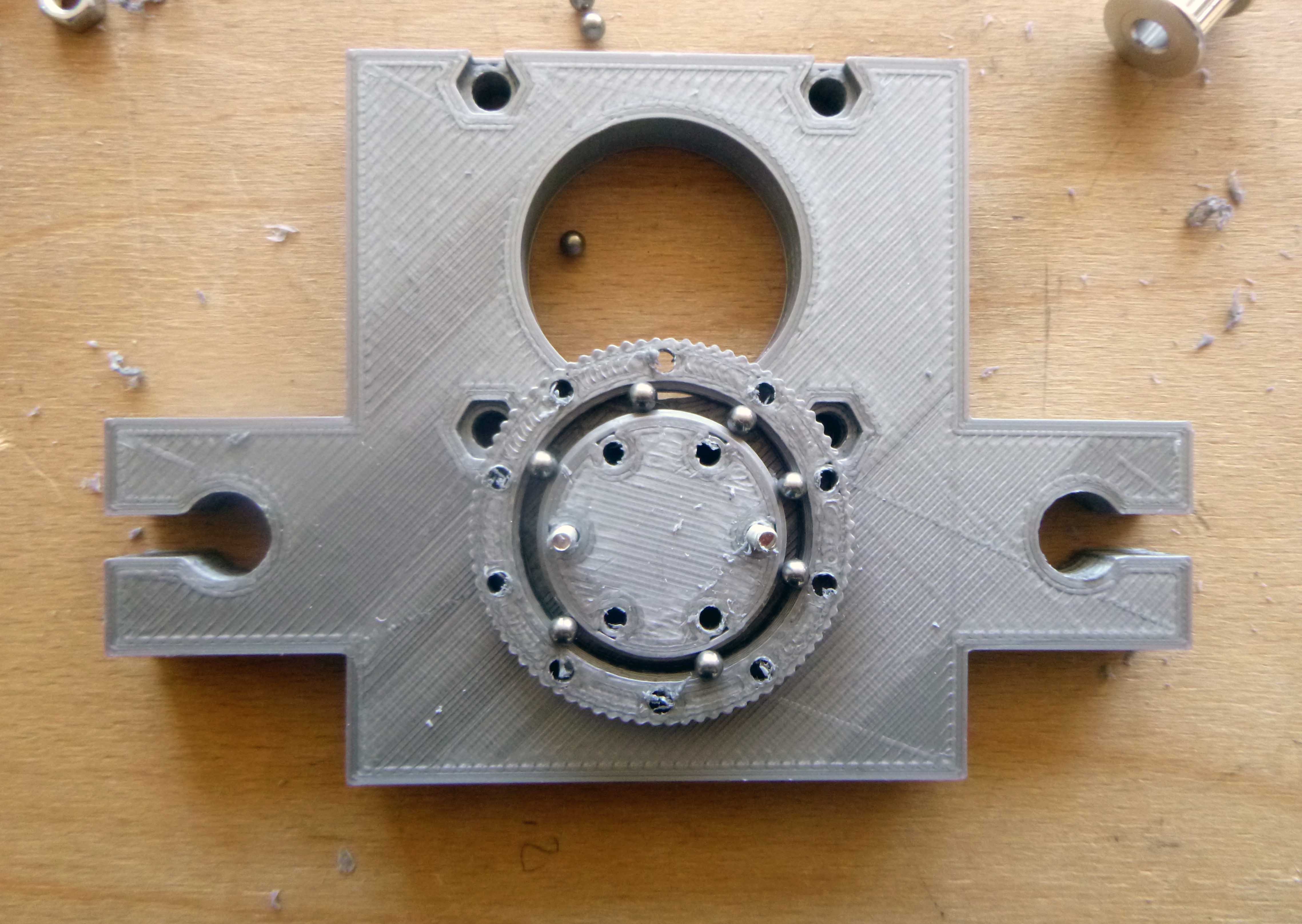
The geared slew bearing assembly is tricky because the bearings want to fall within the inner moat.
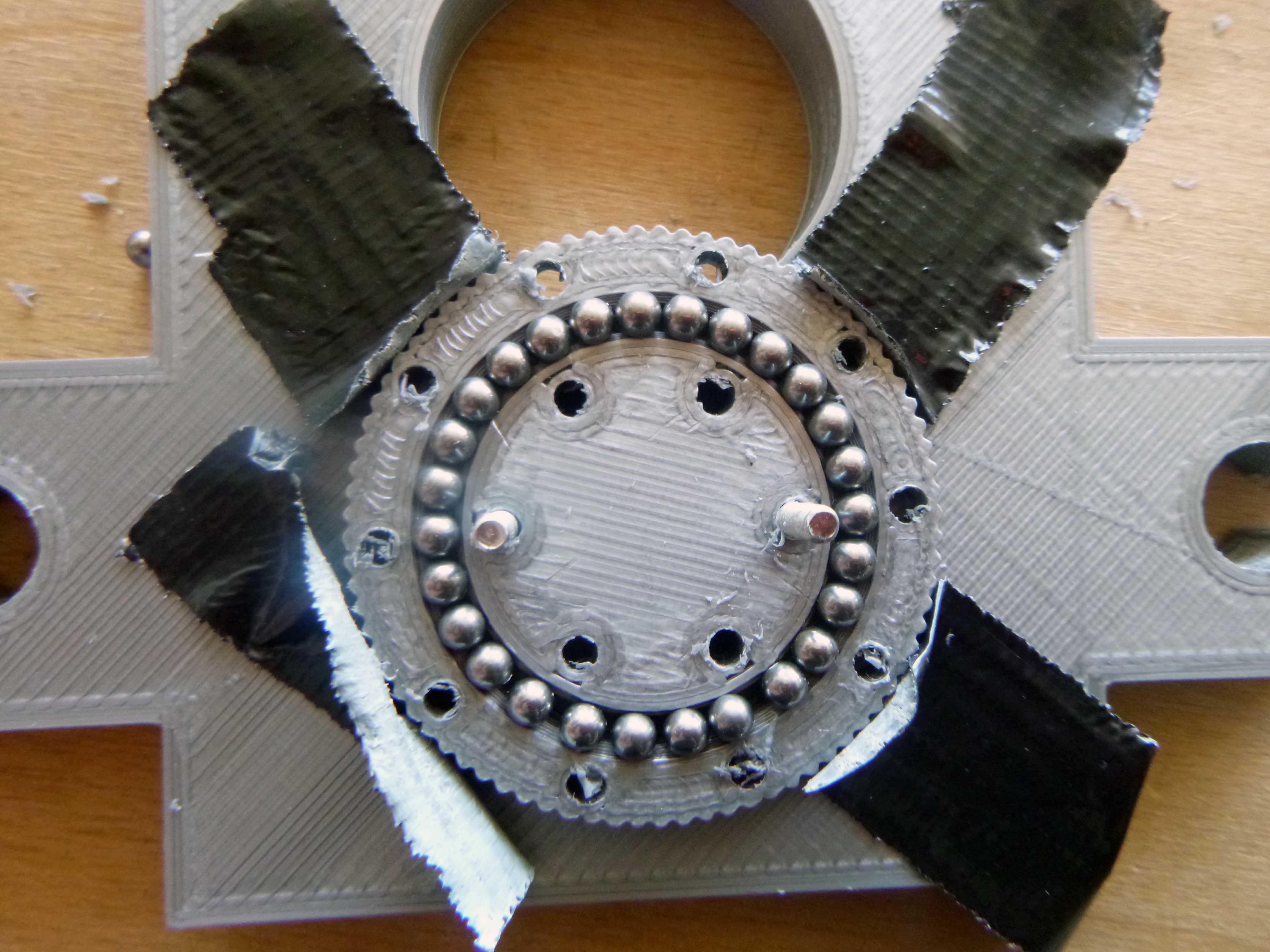
Adding the top bit:
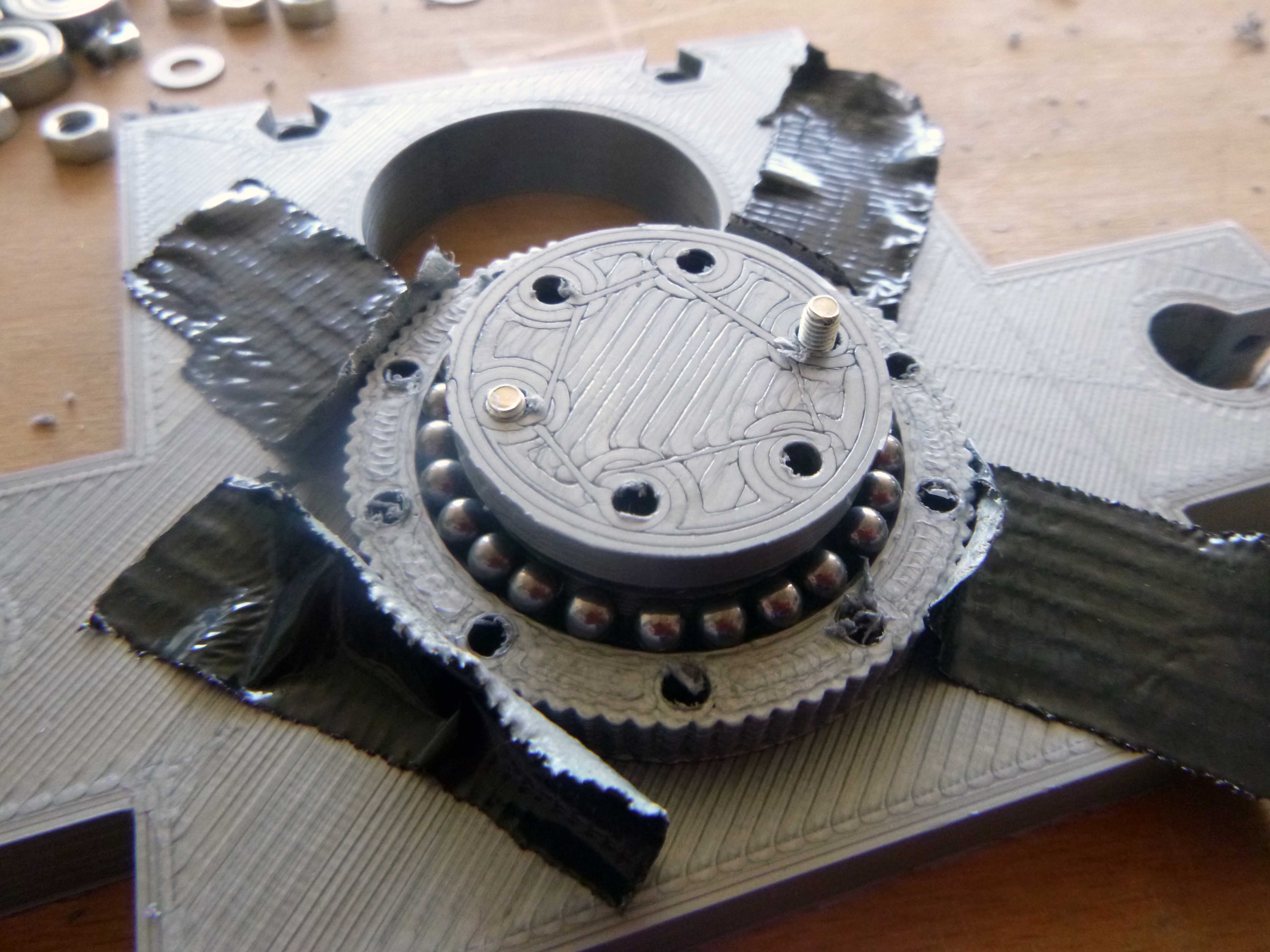
Finishing it off:
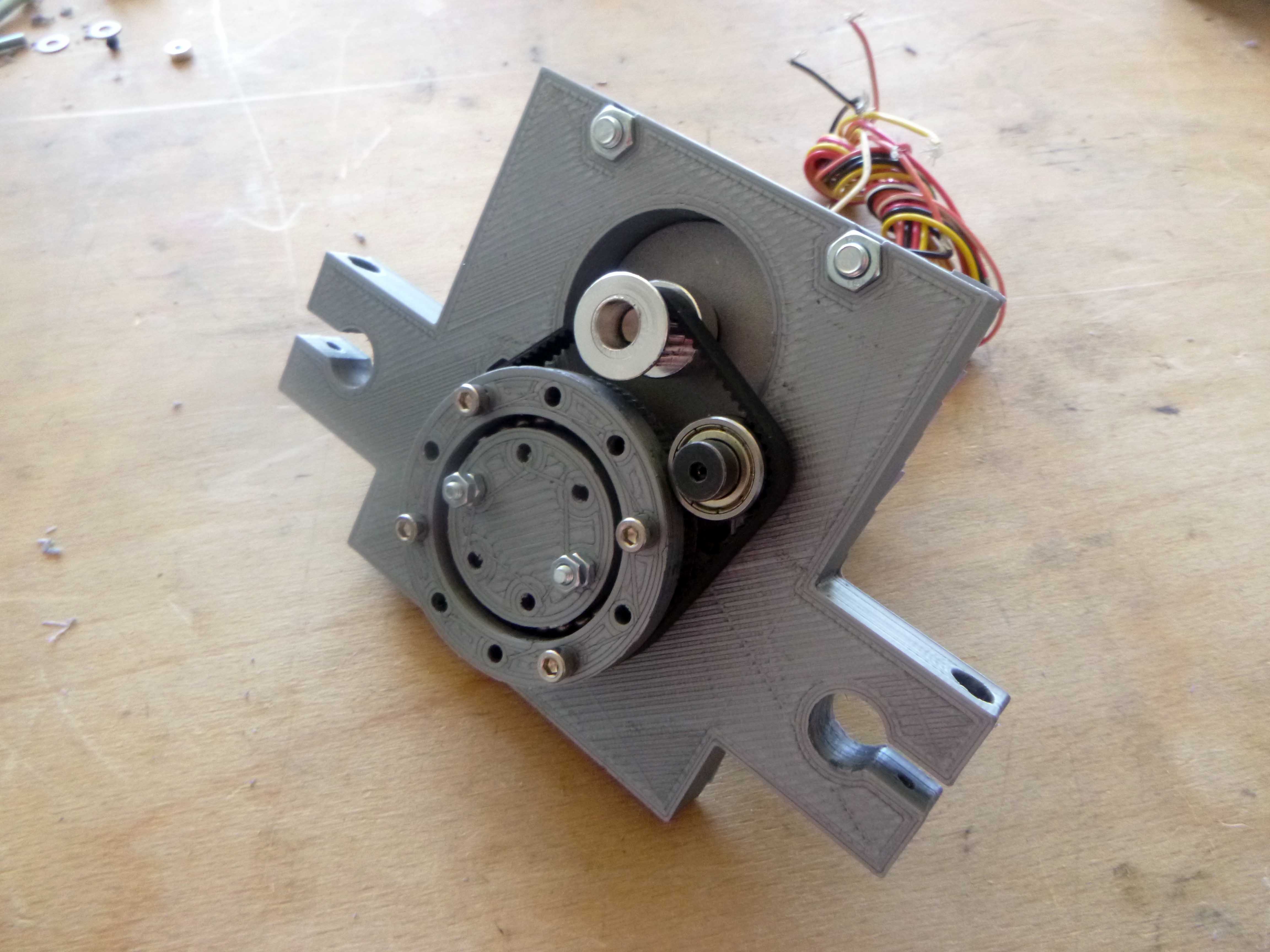
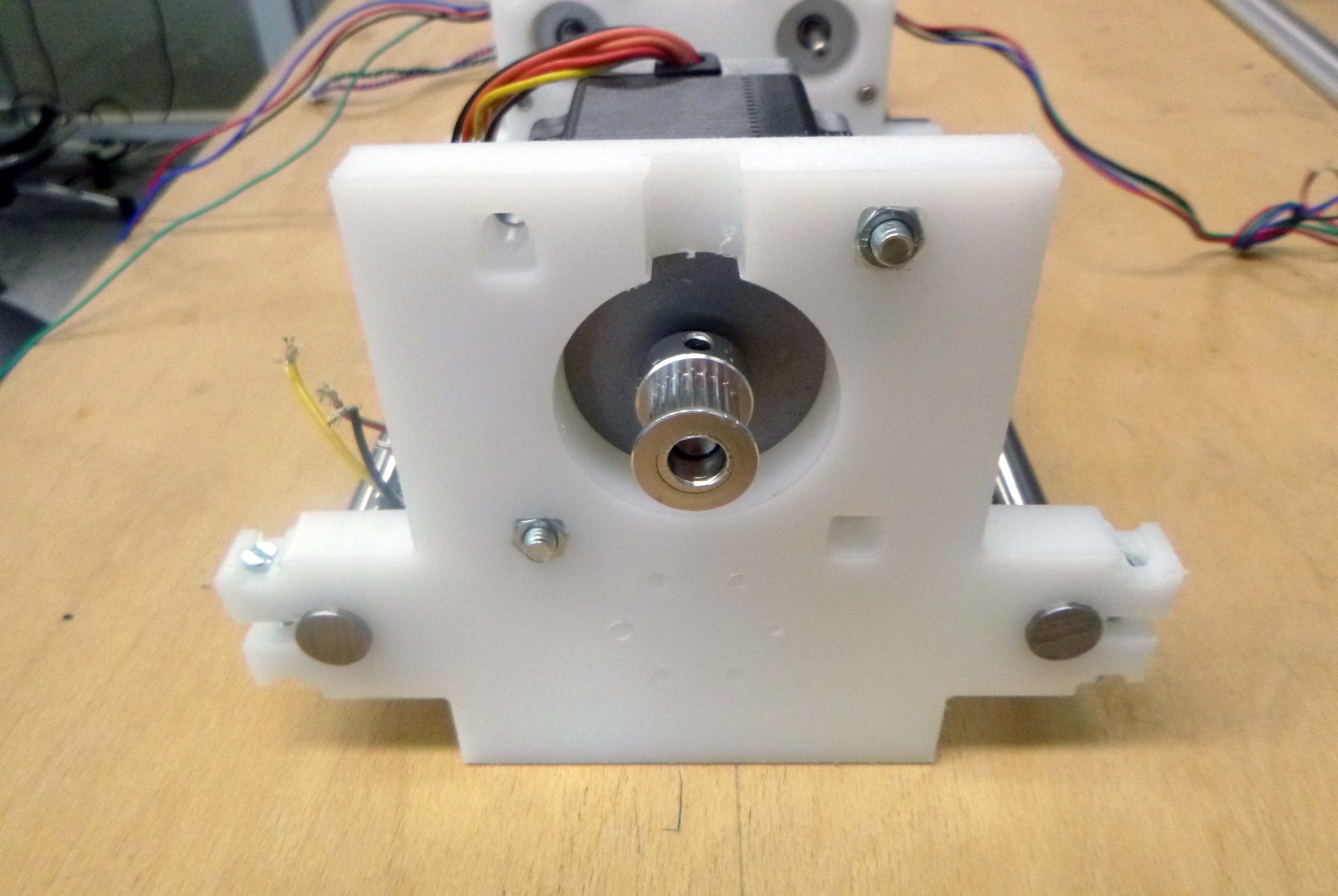
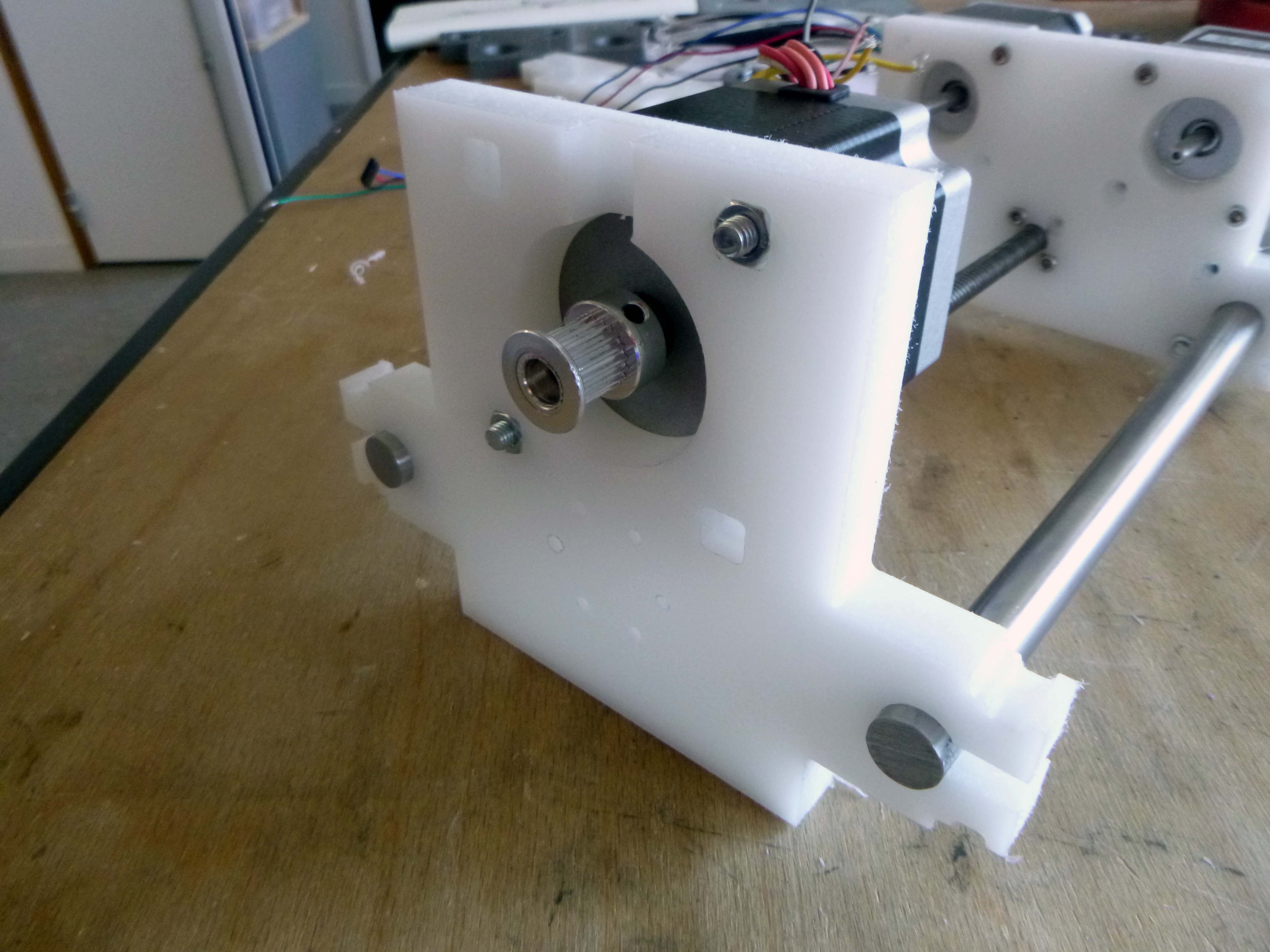
Here is the drive mechanism with an idler I added:
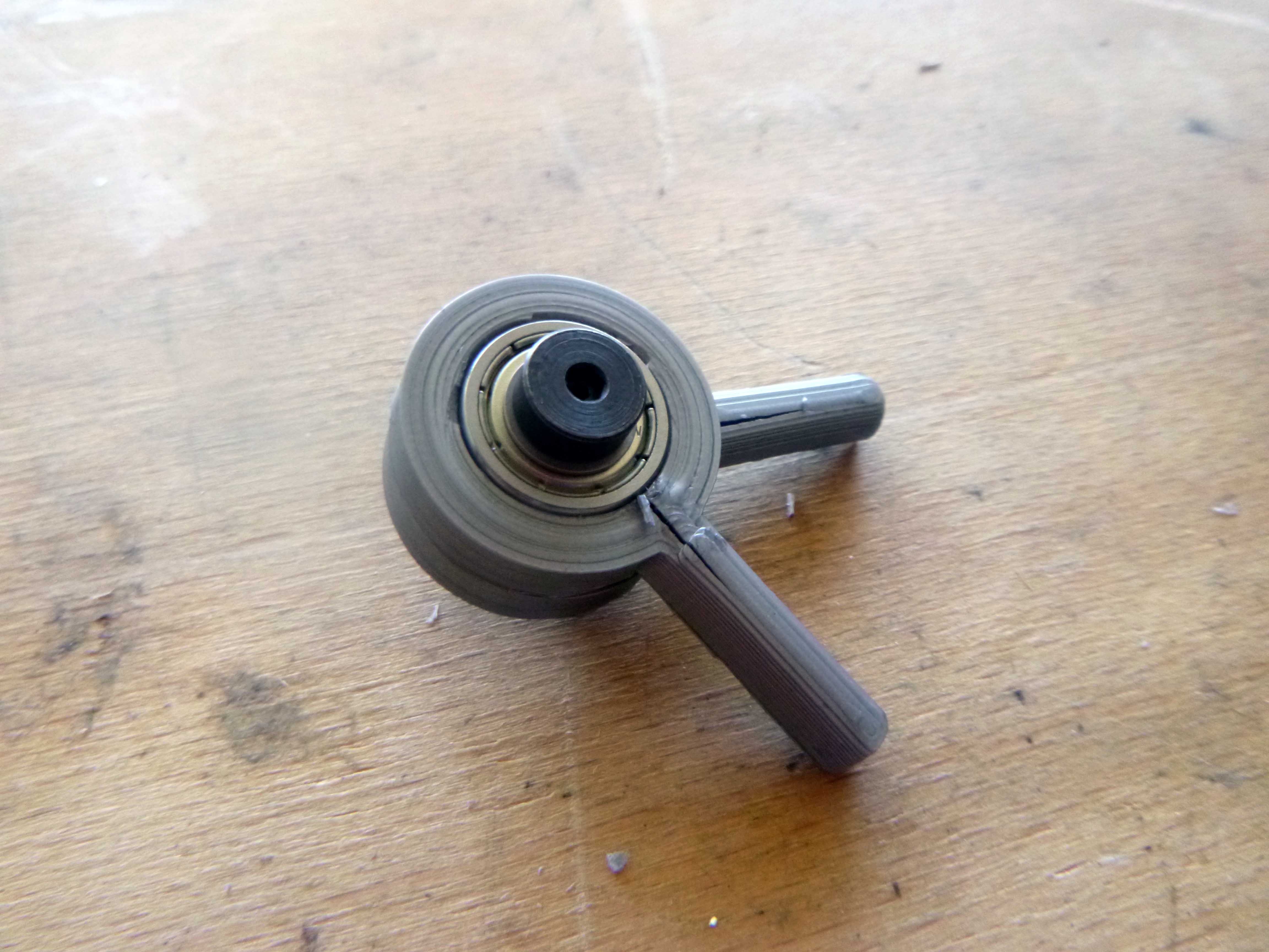
Assembling the parallel robot arm components:
Hammering in the bearings caused splitting in the print…
I sawed the metal bar and deburred before assembly.
 The top threaded rod motor assembly (I broke one side hammering the nut in a little too vigorously)
Despite checking and rechecking I somehow forgot to put holes in the middle of the rod bearings (!)
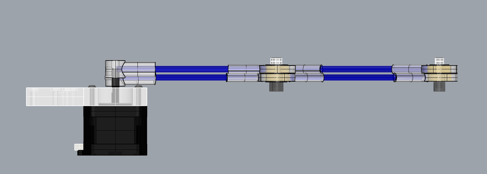
Here’s the linear actuator assembly:
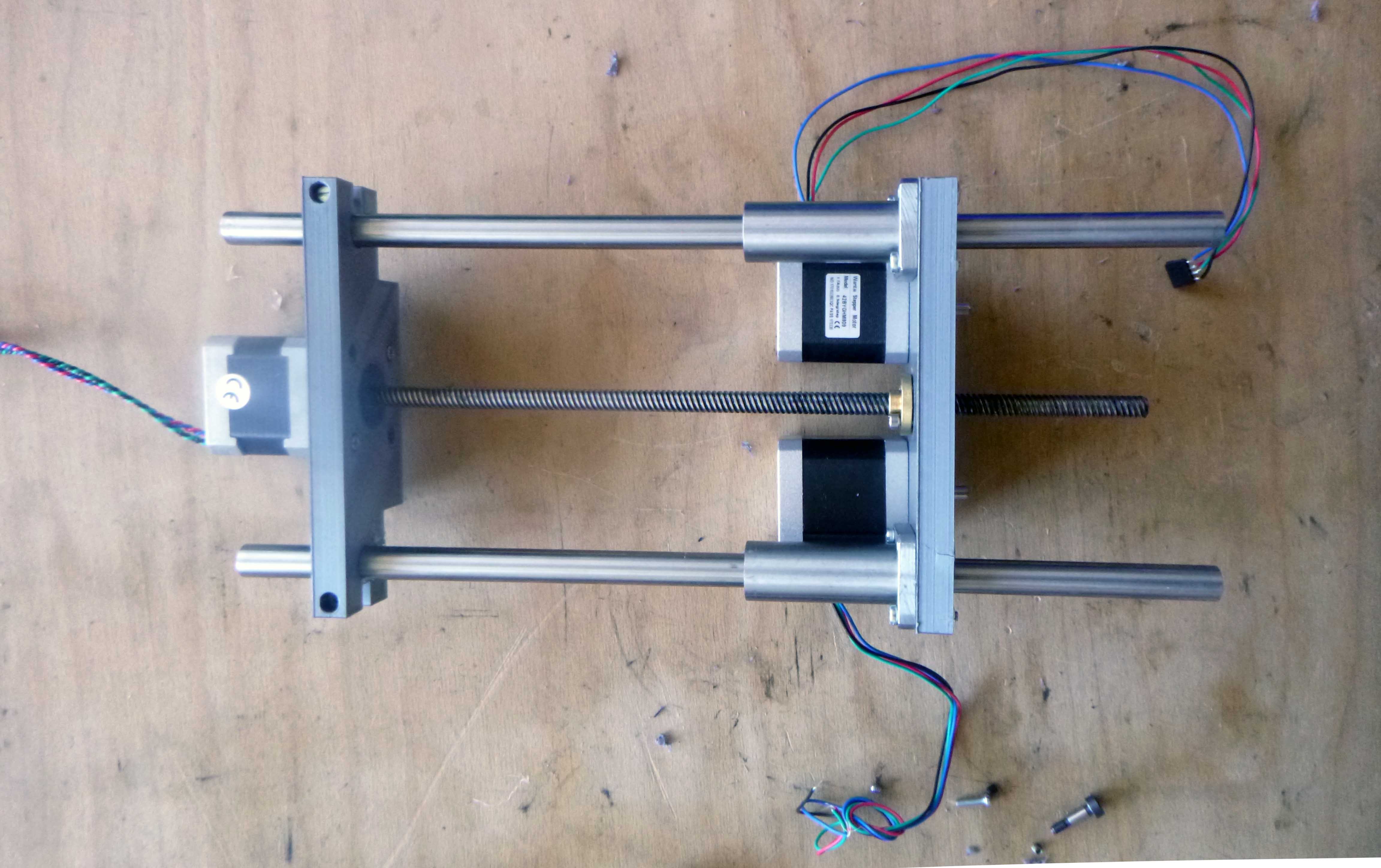
With the parallel arms attached, just waiting for the base to finish printing:
With the base:
Errata with the bottom part of the robot:
-impossible to tighten hex nut to fasten gear to bottom motor axel. (Added slot for this purpose)
-not nut subtractions to help hold bolts which fix geared slew bearing to base plate. (Added captive nut subtractions to bottom of base plate)
-I subtrated a cylinder from the base for the motor gear but this makes no sense as it rotates around and does not stay fixed. (I filled this in)
-With current arrangement the belt between the drive shaft and geared slew bearing was loose. (Either I add a spot for an adjustable bearing or I change the location of the motor to pull it further away…I chose the latter).
****
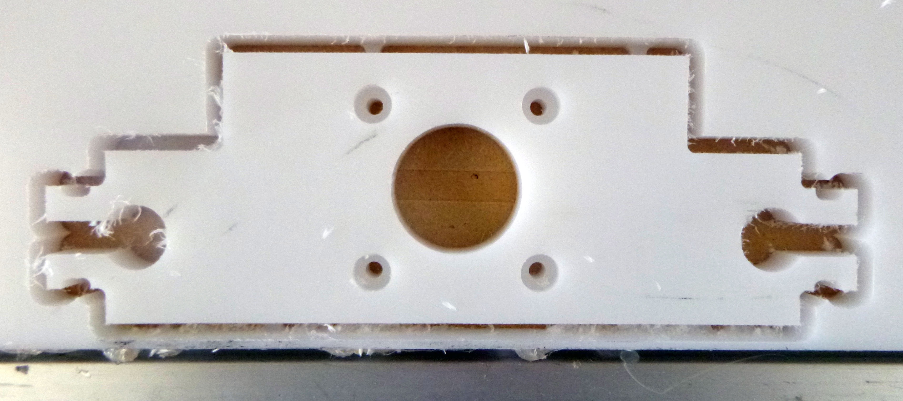
CNC milling:
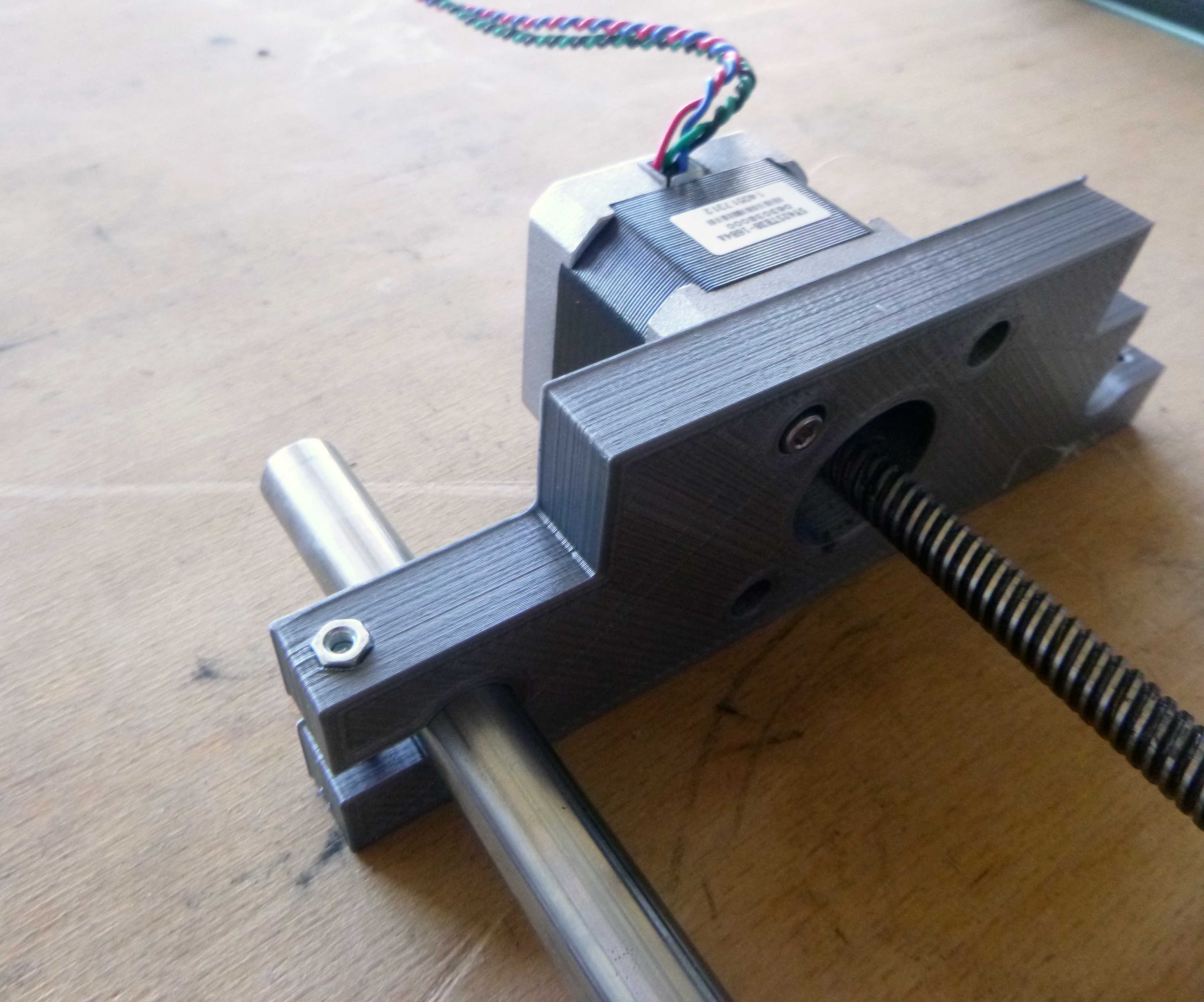
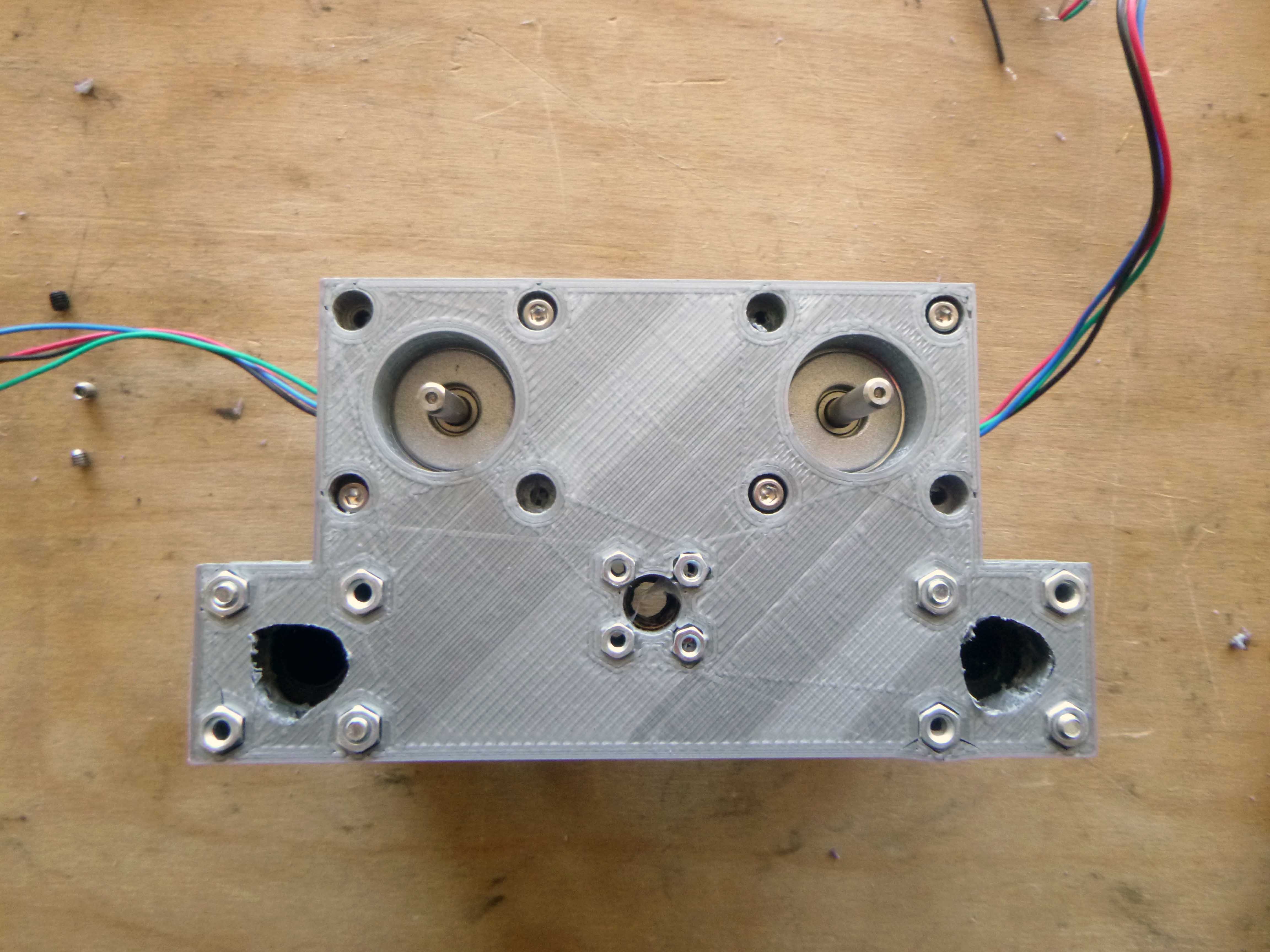
The top motor and rail mount:
I replaced one part of the 3D printed robot parts at a time:
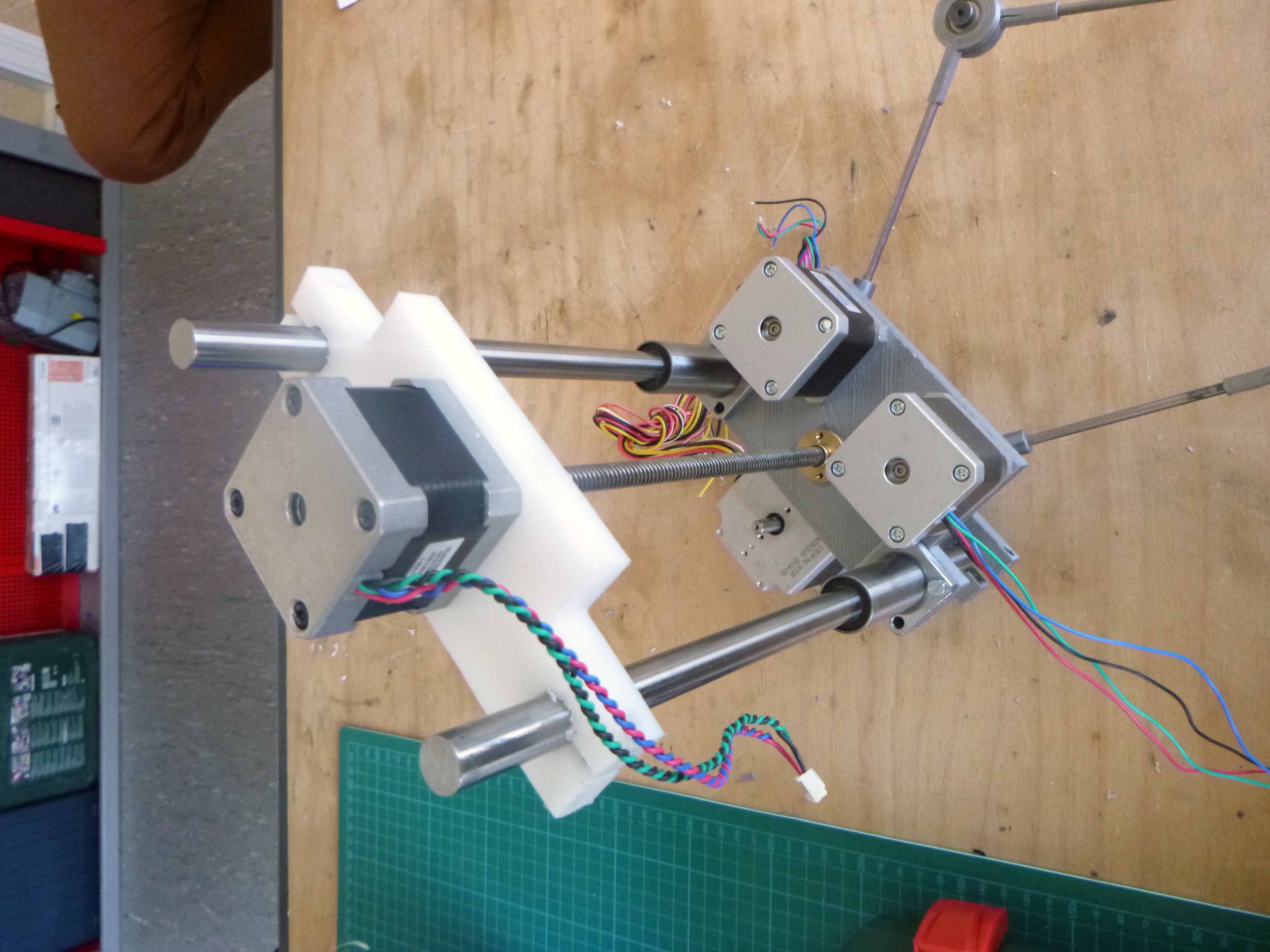
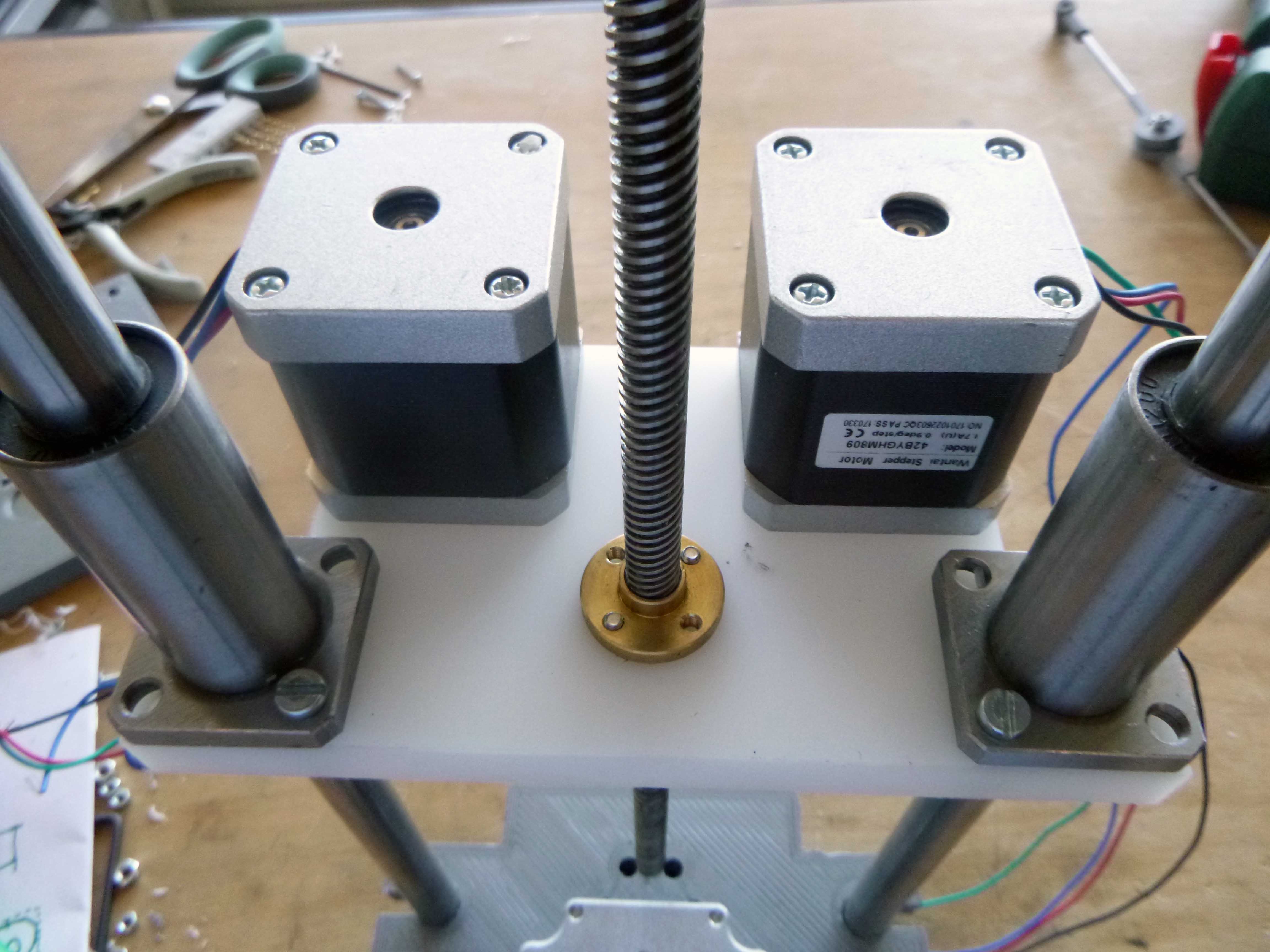
The middle component:
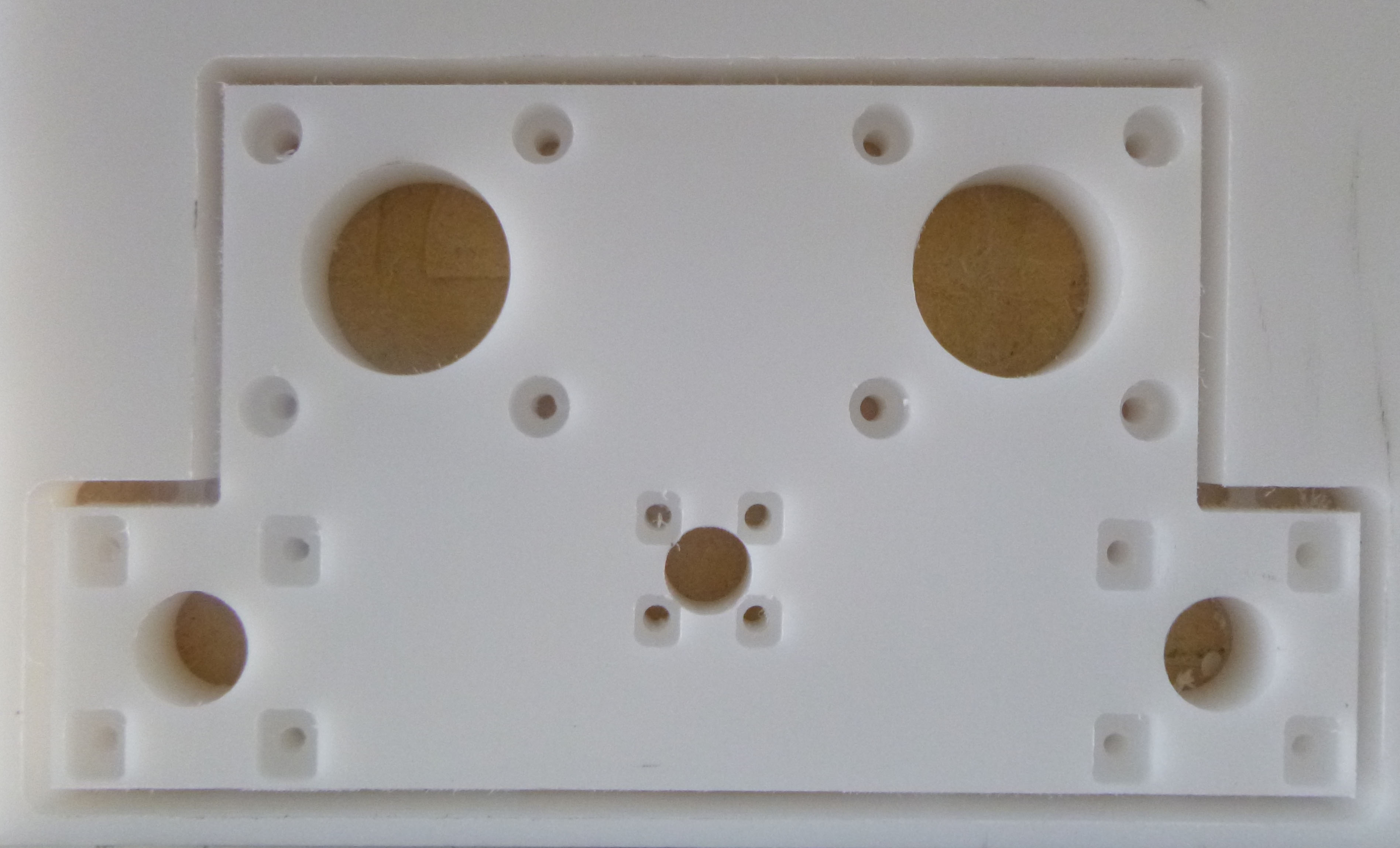
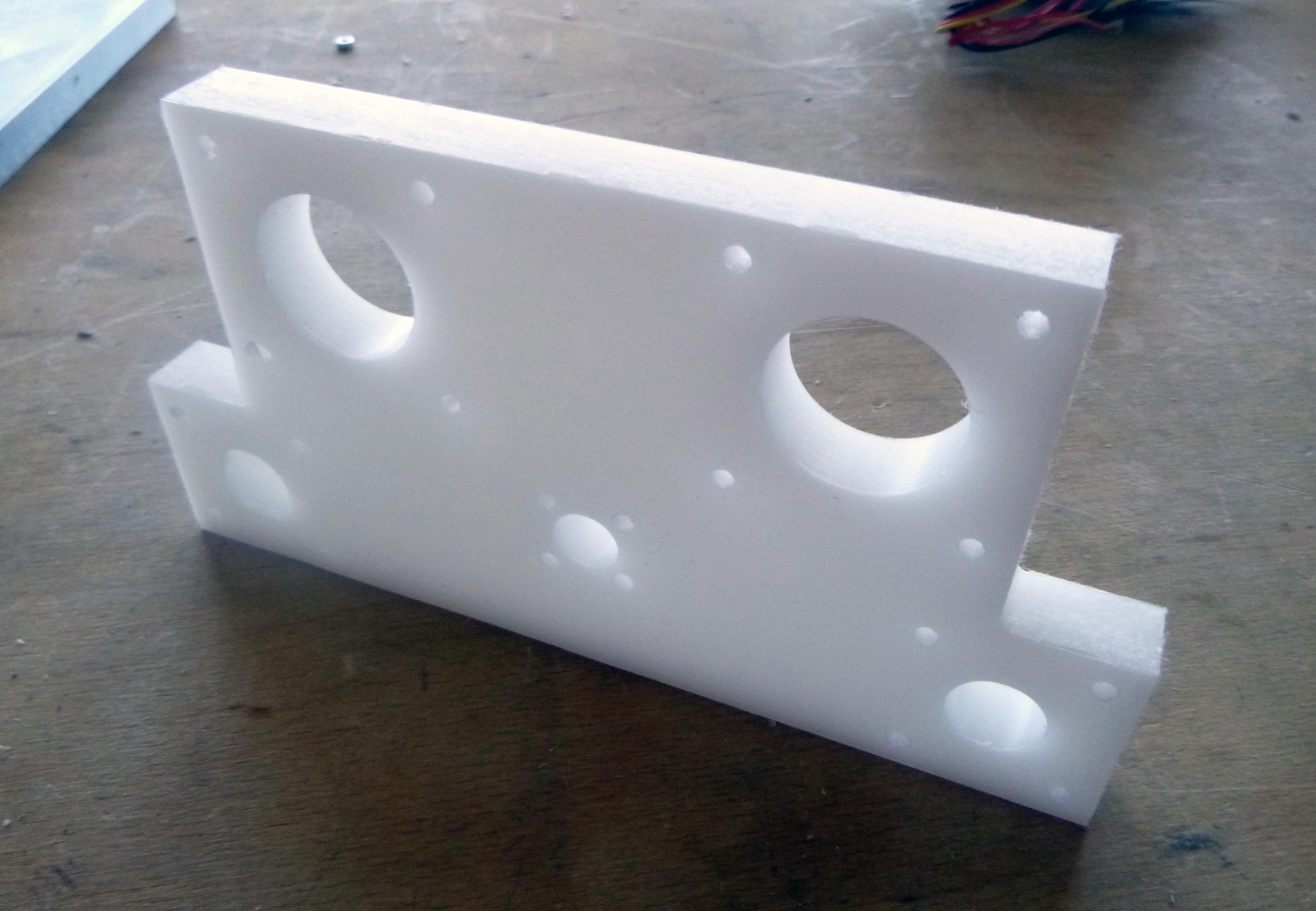
Everything fits together nicely!
And here is the final result:
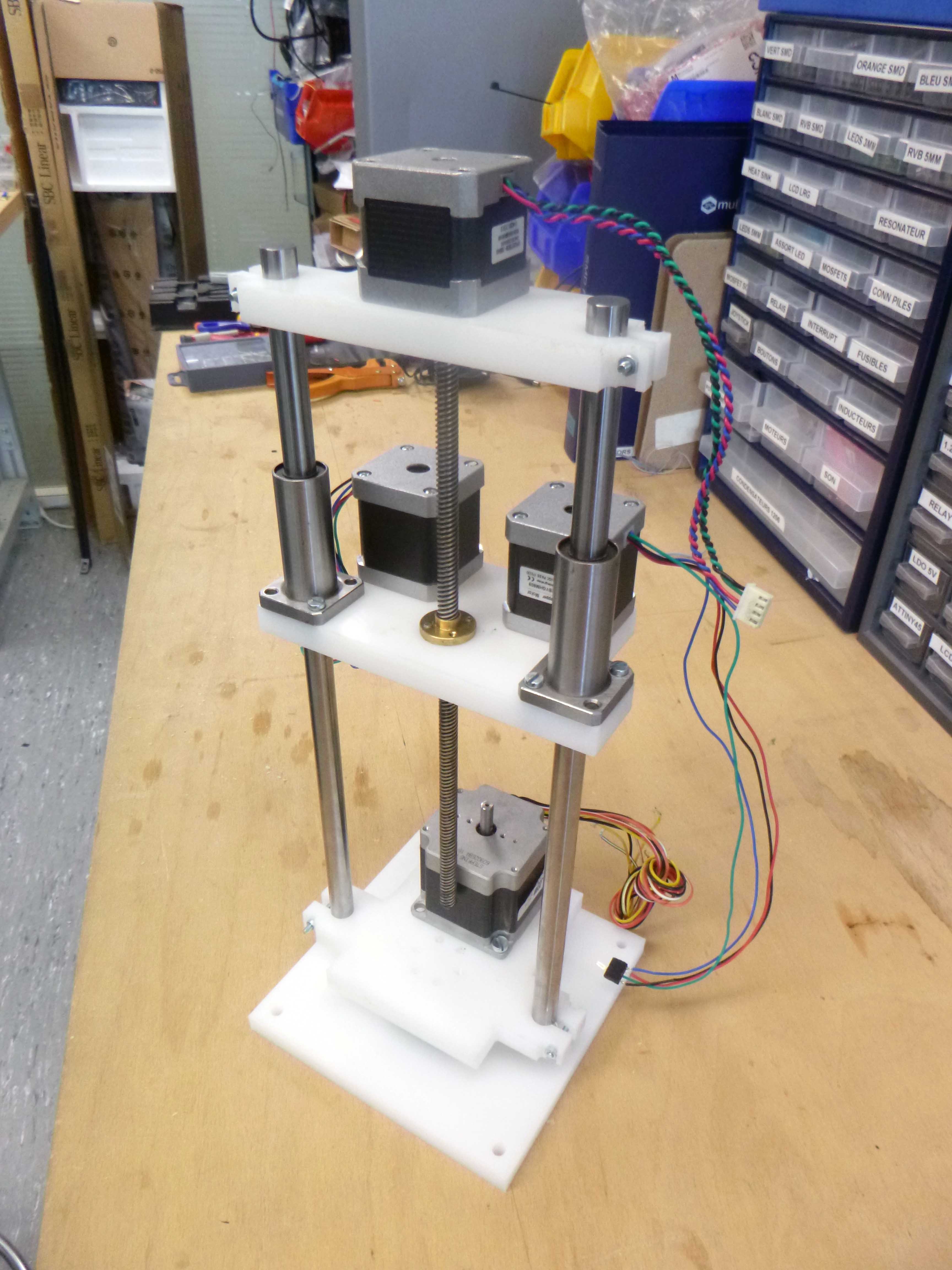
The CNC mill using HDPE is extremely fun to use. The only part that is not easy to make is the bearing assembly. This I will print in durable white resin on the Formlabs.