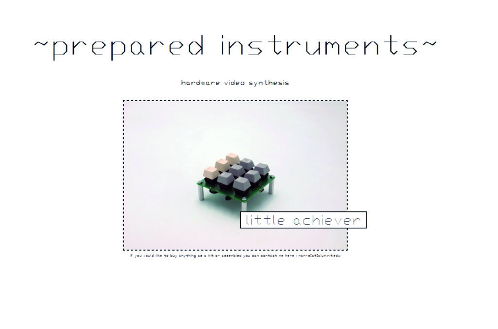
For my first finished product for prepared instruments (preparedinstruments.com), the goal is to remake the hardware 7ch palimpsest.OS SRAM but with :
- a square keyboard grid interface like the PEW design (knobs and switches replaced with keys)
- an aluminium PCB substrate (with a single-sided board) ?
- a simpler amp in path with only one pot
- all 0805 and SOIC packages
I’ve been thinking about it and I can’t say that this board will be inexpensive. If you want to explore video synthesis inexpensively, you should do things for free in code on the computer. This is a physical digital logic / analog device so it will cost money.
Because it’s the first in a series, I would like this board to set the format of the others. I’m imagining them all like Ritter Sport square bars. Like the eurorack format, I would like to have a standard way of powering the boards and I need to decide on a way of jumping between the boards (VGA cables?).
I’d also like the boards and the packaging to be ecologically responsible. I don’t know if this means using an aluminium substrate (which can be easily recyclable in theory) or a flexible circuit (with either a thin plastic or stained steel stiffener – in theory recyclable).
Looking back on the synths from this year, I never really wanted to code/configure the things I made. Doing hardware synths makes sense as it puts me in a different spot in the market place, makes the designs harder to just copy, and it allows me to savour the suffering in the design process. The analog function board was ultimately underwhelming. Going the direction of installation pieces isn’t satisfying because they are too site-specific and local for my project I feel (though perhaps making films is the solution here). The gameboy design made me feel bad about the waste of buying a mini screen and the software challenge of communicating with it seems not crucial to my project (but I will finish at least the physical side of the project to test the layout). The memory boards were the coolest, and of them the layering board is the most elegant design and the most interesting in what it can do.
Here’s the new site where the béchamel will appear:
Thoughts from Vincent :
- Connect with other people making video synths !
- Try shooting some of your own film to put through the machines !
- What is it you are trying to SAY ? Hmm
What is it you are trying to SAY:
I think I’m trying to say with this project is : Look at what I like doing, isn’t it fun and cool/silly/odd what is to be found ?! More specifically, to share the preliminary results of my creative research project method. The project I guess is trying to say that it is possible and fun to a embark on an explorative creative process with technology at a low level (and not just use pre-packaged tech things) with some of the wrestling with constraints that that requires. I like that the objects are idiosyncratic, playful compositions but also that they are ornately routed and articulated. I like the message that machines can look different, and be more human and odd ? I guess I’m also trying to have fun with the ideas of usefulness and futility, so it is partially supposed to be humorous? I like the détournement of industrial objects for playful means, the implication that old things can be exciting and that deconstructing a system reveals unexpected inner worlds. I like that the deconstructing of machines is also the deconstructing of how they interact with our world, like the data they save and how they represent our information.
Thinking that Alterity, oddity, idiosyncracy and animism in objects and people and culture I think are totally up there. This was a fascination of my dad’s.
To echo some artists’ quotes that resonate : “I don’t know what I’m looking for until I see it.” (Cindy Sherman)
“The reason I play so many sounds, maybe it sounds angry, is because I’m trying so many things at one time, you see? I haven’t sorted them out. I have a whole bag of things that I’m trying to work through and get the one essential.” (John Coltrane)
I want to learn things all the time, I want to understand the patterns behind things. I experience science through craft. With craft I try to cultivate sensitivity in a practiced, purposeful way. If you work with marbling you know just as much about viscosity and flow than a scientist, through your fingertips in a different way. (Tauba Auerbach)
Try shooting some of your own film to put through the machines?
I started thinking about what I would want to film and how. I thought about the beautiful cinematography I appreciate in special films like The Souvenir I & II. I think it would be cool to shoot some video because I spend a lot of time watching videos (not the case for writing because I don’t do enough reading). I thought about recording things I see on commutes, and about the forest walk in Saclay. This has made me consider that what I find interesting about the electronics side is memory, more than just modifying things with math. How the computer represents our world is mainly impacted by its ability to remember it. I’m starting to think that this project could be about memory, putting my own memories into the computer memory. I’m thinking about Iain and Brian’s film Lifesaver and the impact it’s had on me. Also Iain’s photography in general, especially his black and white stage.
I think DRAM board could be a cool project because of how inexpensive large memory is and the memory degradation which could be really poetic in a project about memory. This goes back to Paolo’s suggestion to make a project around an image put into UV erasable EEPROM and watching it slowly degrade in the sun.
I’ve been thinking about how to record as well, with a gopro discretely or with my G2 Cannon more deliberately. I also think that humor should be the primary part of my shooting, not some wanna-be poetic stuff.
**********
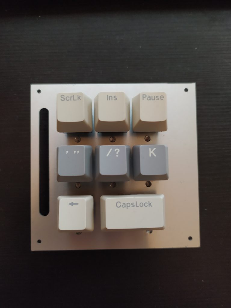
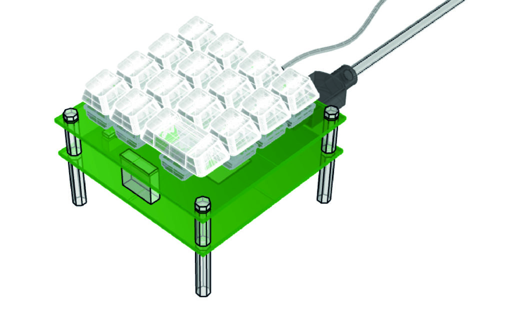
Trying to design the interface :
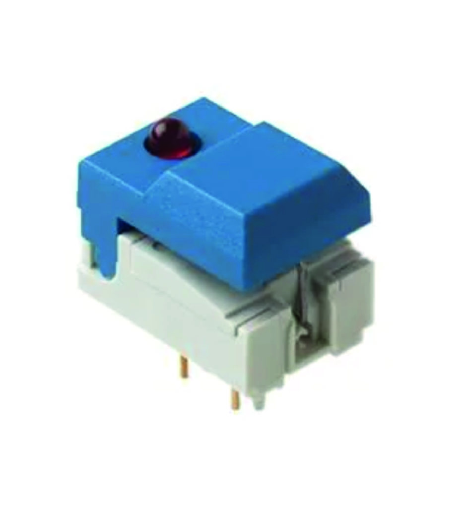
Might need latched buttons like this :
Some all metal heavy duty toggle switches look cool in an array but I’m worried toggle switches will require too much force to turn on and will therefore be annoying all arrayed together on a tiny board.
The other option is to stick with tactile buttons and to convert them into on/off buttons with a JK flipflop. When J and K are pulled high, the outputs Q and !Q toggle every time the clock rises (once per push). This would mean I could have an LED turn on when you push too (helps in the dark for performances!) but I wouldn’t have the pushed-in versus fully extended visual feedback from the button and it would add ICs to my packed board.

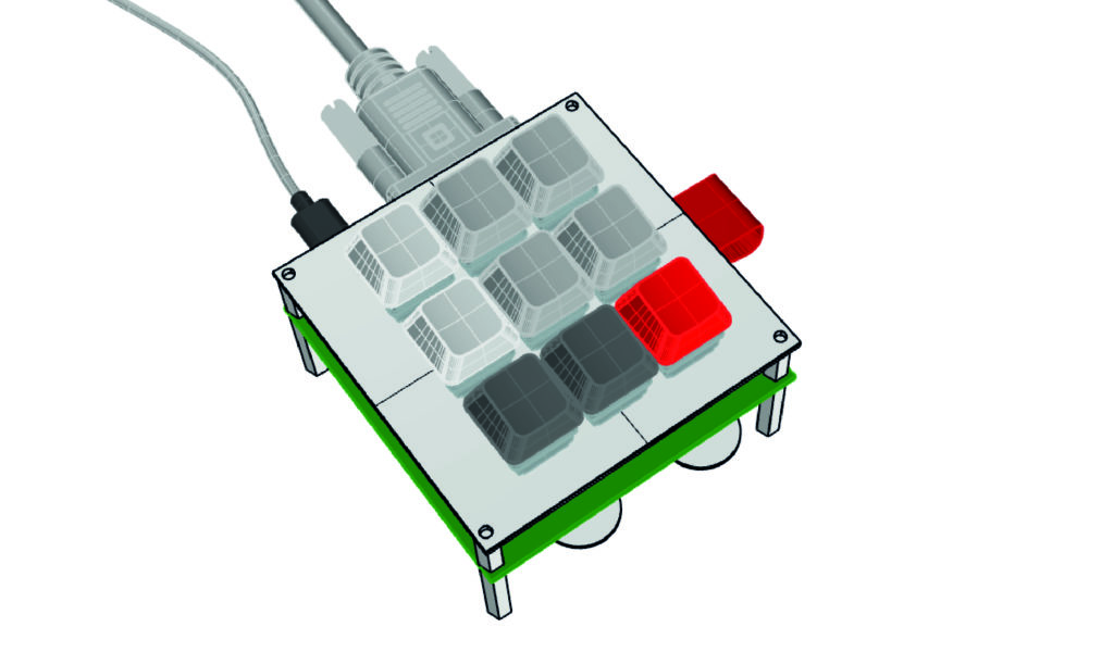
I am considering doing this on two boards, the top one would be a single-sided aluminium board which would look cool but also make the top interface more durable. This board would have the leds, keys, JK flip flops. The board below could have lots of space to be laid out in a relaxed, rational way without having to dodge buttons. I could enclose it in a little box or I could leave the two boards exposed on one side or all around.
This follows from the constraint that this will be a real product. I don’t want to make a super difficult to solder and debug highly compact circuit. I want to keep things easy to repair. It also makes the device modular, I could switch a new keyboard and keep the base circuit or vice versa. I would like to keep this device affordable and not using rare / exotic components. I’m more in the robust, standard design world now that Tommy is good at working with perhaps.
*******
I just cleaned by apartment and went through my lab equipment. I will be sending tens of boards and plastic bags to the recycling which makes me sad. I would like to avoid finding myself in this situation in the future.
Check out this Soviet-developed visual programming language DRAKON (https://en.wikipedia.org/wiki/DRAKON)

It would be cool to make a flow diagram like this for the FPGA code I’ve already made.
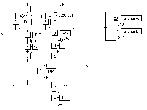
Also this automation representation called GRAFCET (https://fr.wikipedia.org/wiki/Grafcet)
*******
Check out these user interface principles (https://en.wikipedia.org/wiki/User_interface_design):
- Clarity: the information content is conveyed quickly and accurately.
- Discriminability: the displayed information can be distinguished accurately.
- Conciseness: users are not overloaded with extraneous information.
- Consistency: a unique design, conformity with user’s expectation.
- Detectability: the user’s attention is directed towards information required.
- Legibility: information is easy to read.
- Comprehensibility: the meaning is clearly understandable, unambiguous, interpretable, and recognizable.
********
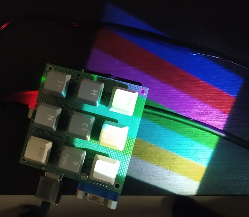
Just watched a Youtube video by Code Aesthetic called Don’t Write Comments. The implication is that the code should be so readable that you don’t need to comment it. (He organizes code in such a way that the high level architecture comes through and if you want to get into the details you can check out individual functions). I’m trying to do something similar with the interface, have it be directly readable without text just based on color, button size and location.


I like the idea of being more pragmatic with the design and less obsessive about composition. The cut away in the top board could be nice because it show which color bits are going from rpi to the memory.
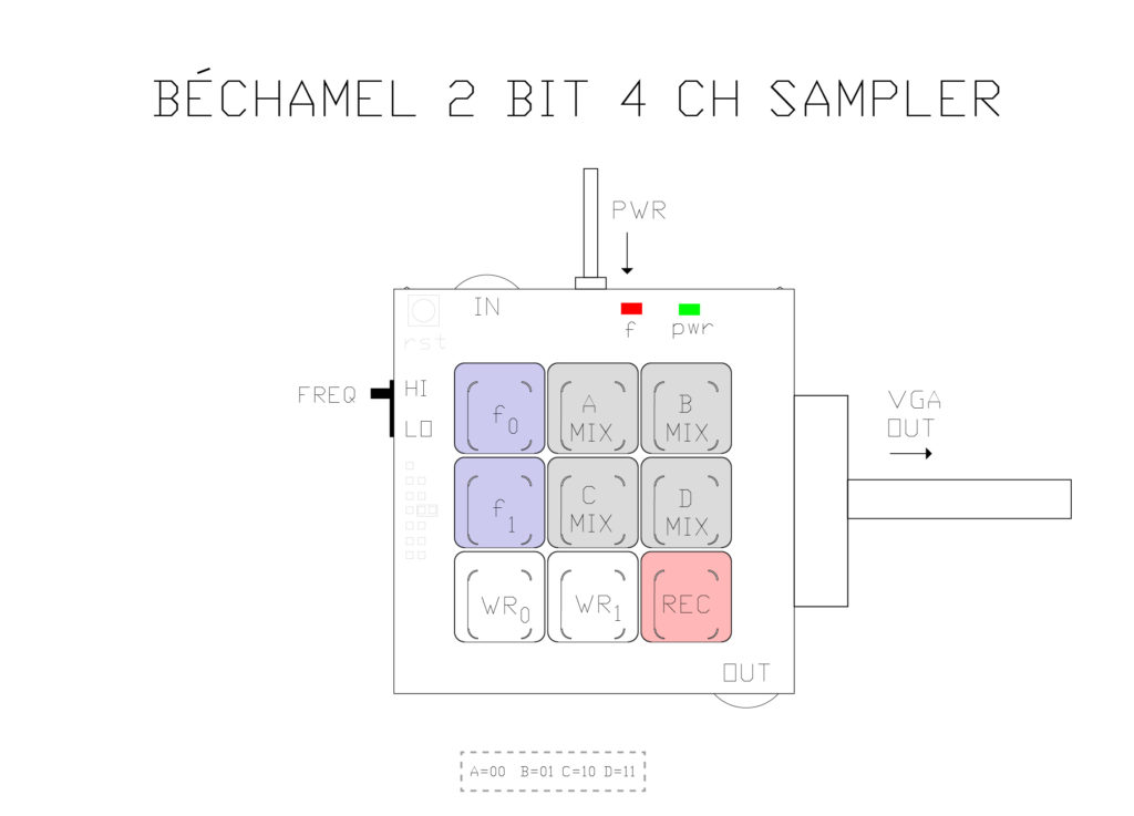
The question of the colors is tough – RED is for recording ? Should colors follow RGB ? What colors for clock division, and for selecting between MSB and LSB ? What about the LEDs versus the buttons ? EDIT : I’ve sinced moved to greyscale…
****
Being creative in different ways : Apollonian (rational thinking, order, logic, prudence and purity) vs. Dionysian (irrationality, chaos, passion, emotion and instinct). Electronics and logic circuits are clearly Apollonian, and the effects they create on screen are more Dionysian.
****
Looking into code bloat I learned the Unix philosophy of “do one thing and do it well”. Other programming credos :
- less functionality (“worse”) is a preferable option (“better”)’https://en.wikipedia.org/wiki/Worse_is_better)
- “Keep it simple, stupid!” (https://en.wikipedia.org/wiki/KISS_principle)
- rule of least power is a design principle that “suggests choosing the least powerful [computer] language suitable for a given purpose” (https://en.wikipedia.org/wiki/Rule_of_least_power)
- a simple (low complexity) solution to a problem of high complexity is seen as elegant. (https://en.wikipedia.org/wiki/Elegance)
**********
New Prepared Instruments github : https://github.com/preparedinstruments/bechamel
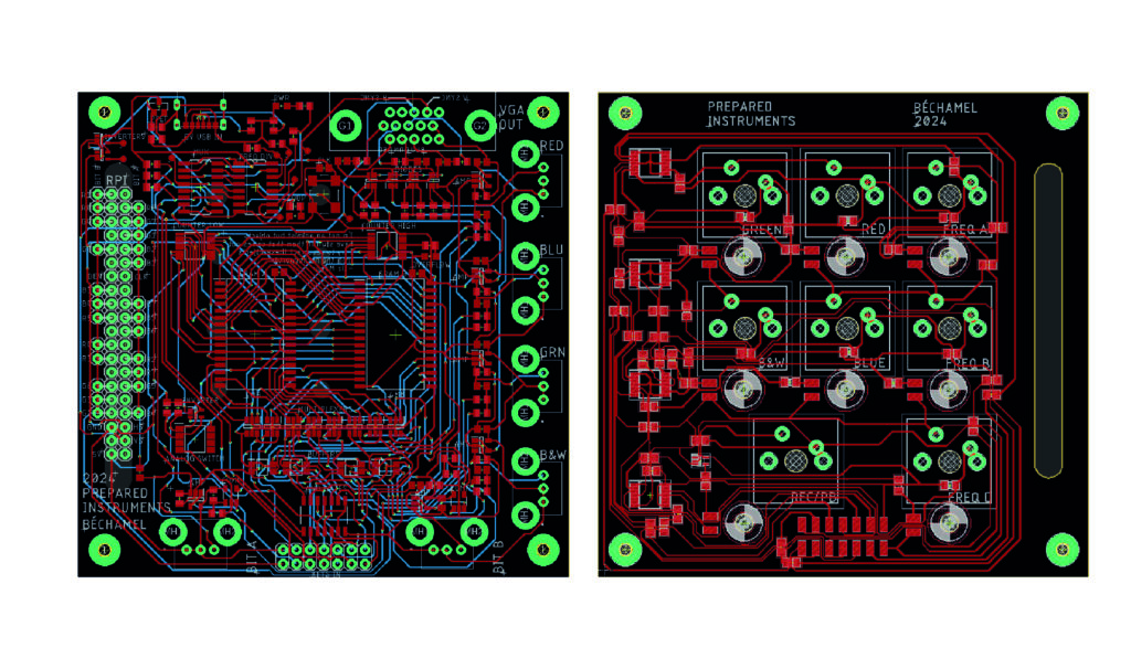
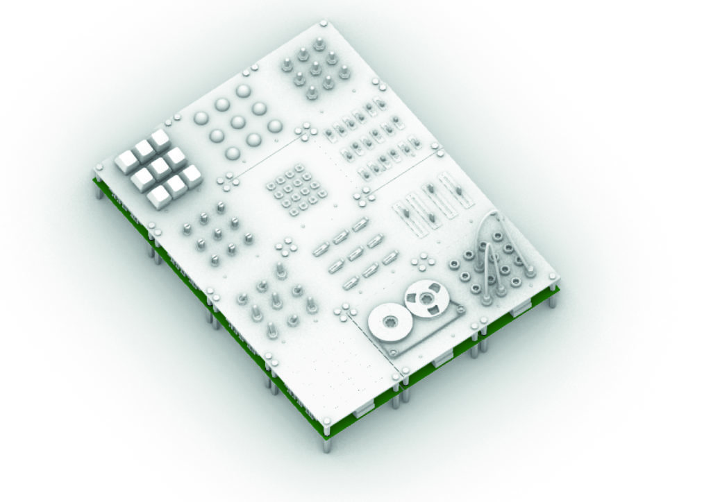
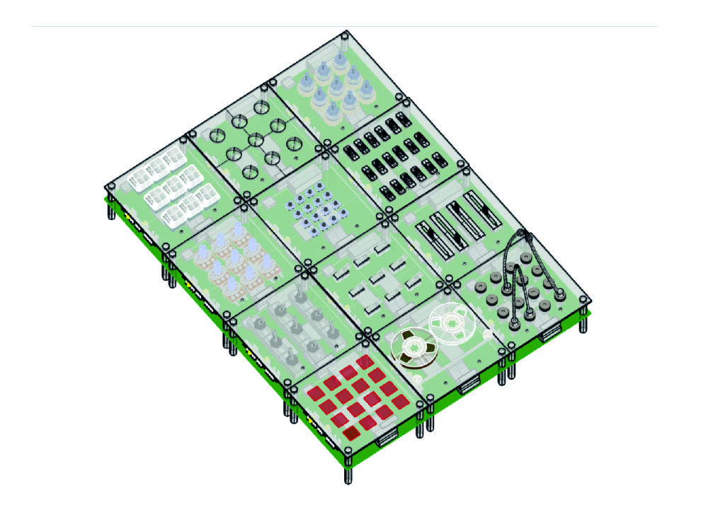
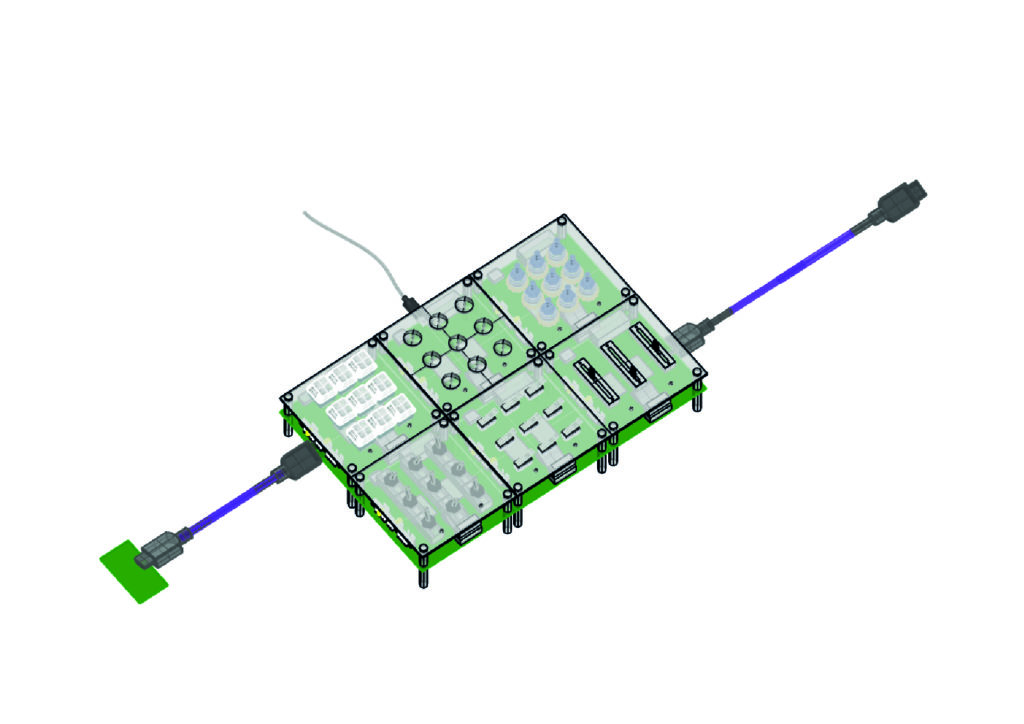
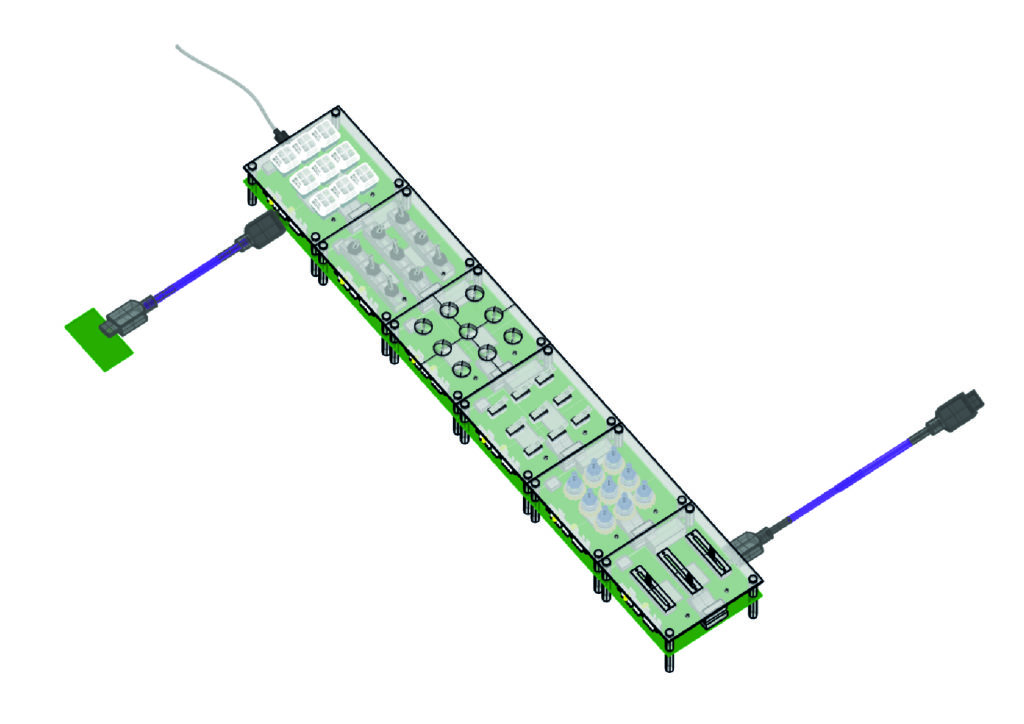
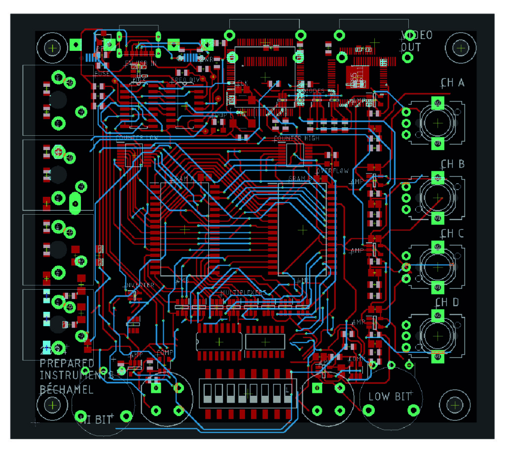
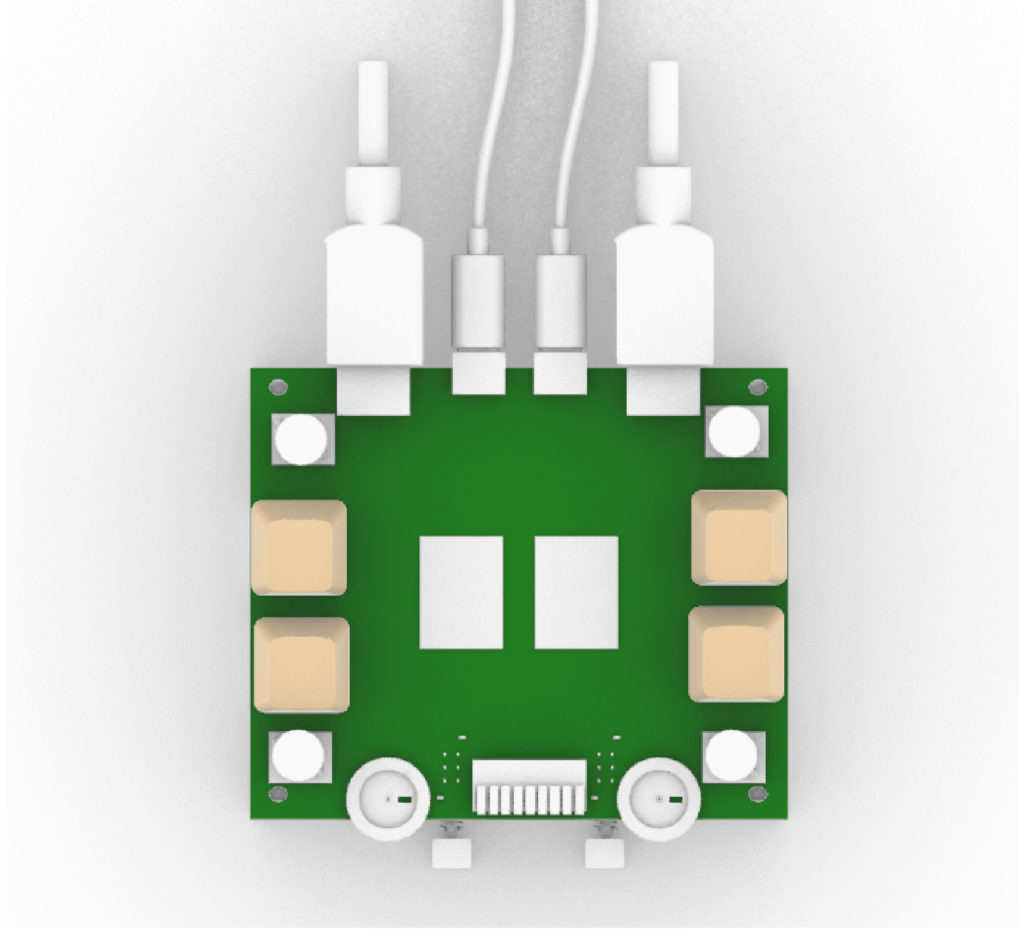
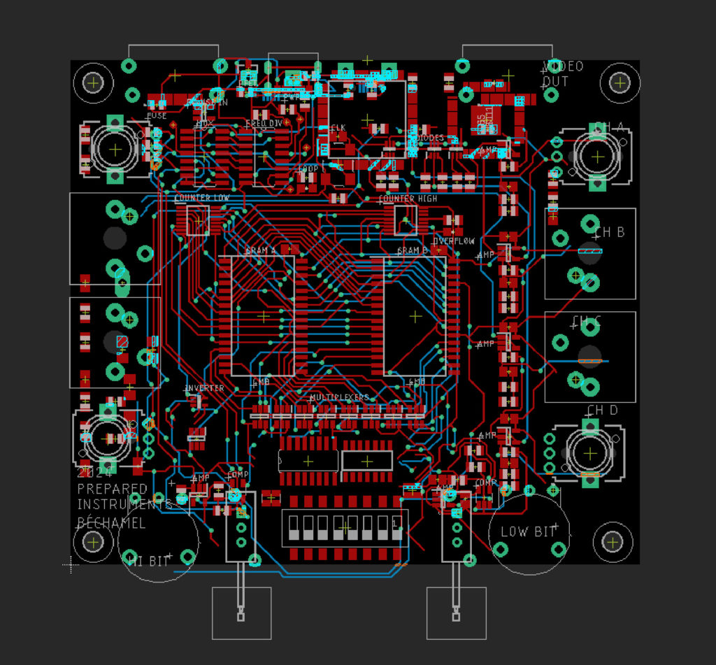
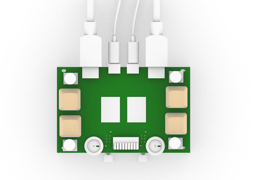
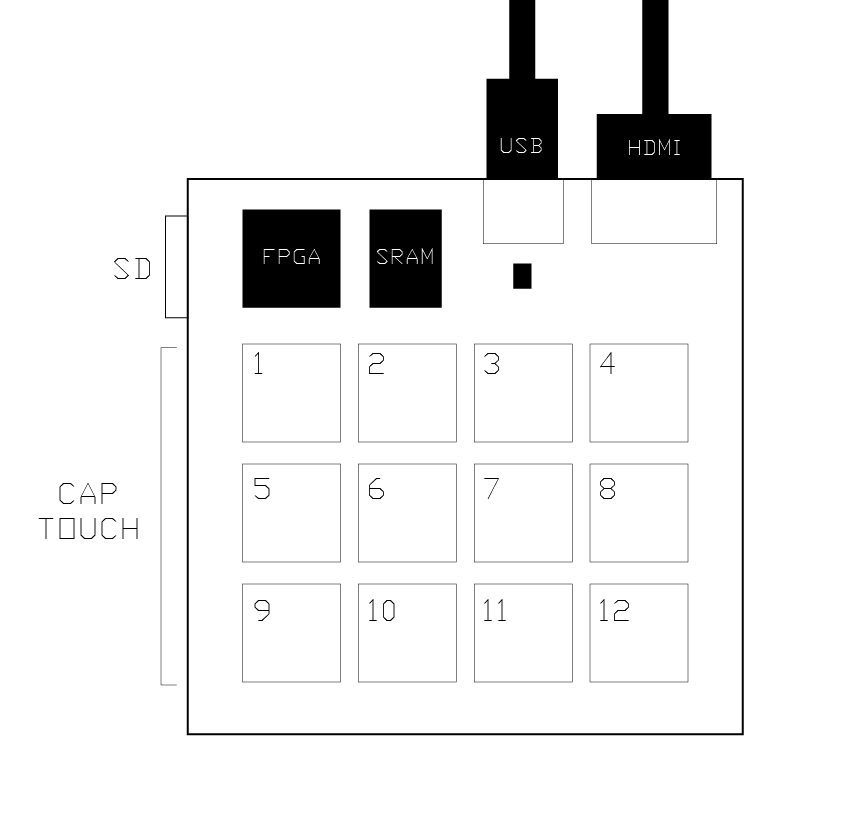
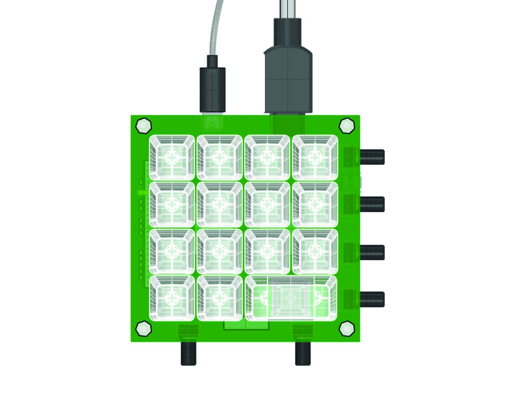
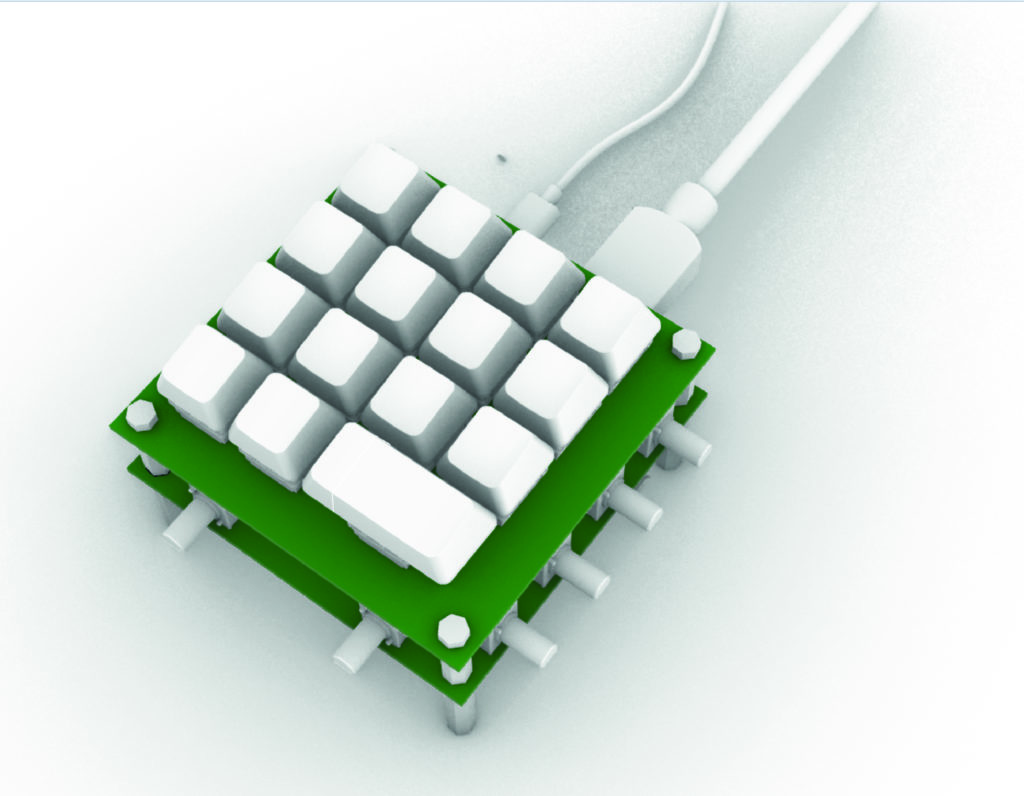
OK, here’s the final version of the boards. I will finally be able to test the one-sided aluminum surface reversed with buttons going through-hole. This is (my first) double-board design, keyboard on one and memory on the other with a ribbon jumping between them. This sampler will have two bits of data for the videos which will be new. Layers will now have different colors associated with them. The gen lock turned out to not be what I thought it was so I’m trying to sync by using V and H syncs (and their inverses) connected to the 590 freq division somehow (either to OE, CLR, or RCLK). I like this new setup to select different bits of the RPI. Cool things here are the double use of the buttons in momentary and latched mode with led indicators. New in this version will also be the triple diode packages for the VGA out.
I’ve taken my favorite interface and mixed it with my favorite circuit, let’s see how it works out ! At least I got to use up a bunch of components I already had lying around. Though, I have to say that no one could pay me enough money to assemble one of these myself, and despite my best efforts it is not minimal and easy to put together. Another issue is the fact that I don’t have the skill of imagining what “customers” want, I seem to be more focused on what I want. Does that make me a wanne-be artist as opposed to a wanna-be designer ?
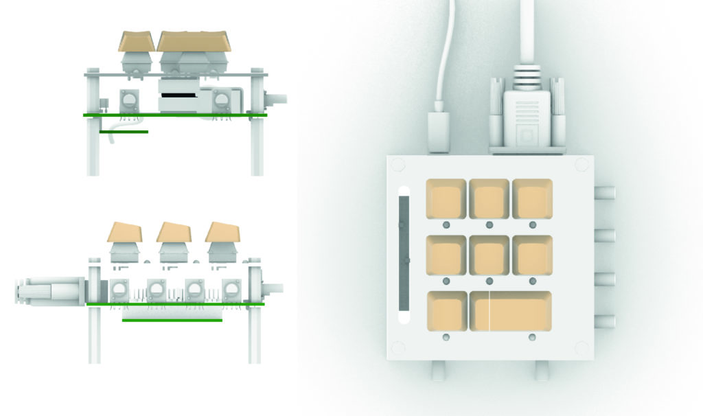
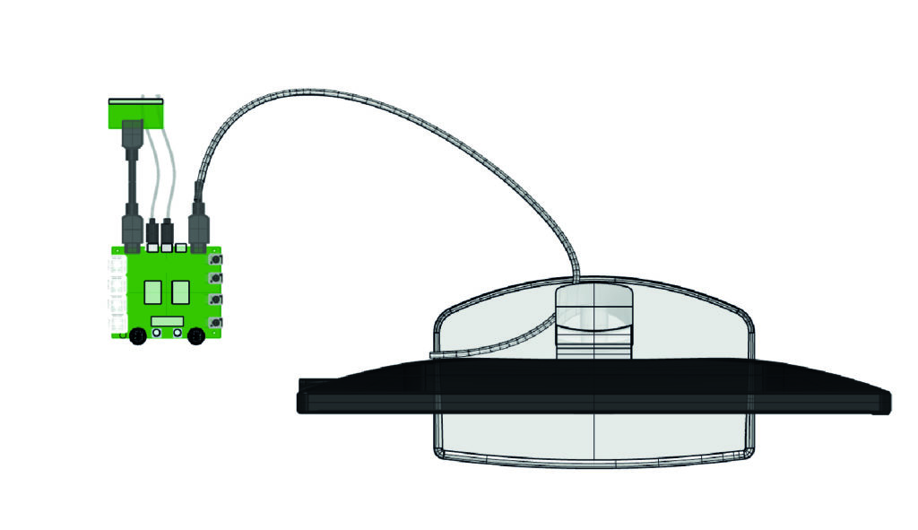
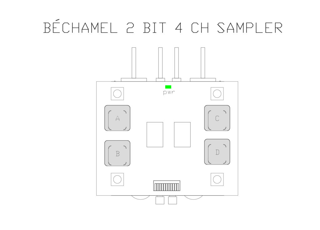
And some renderings :
**********
Having a think about what my hardware synths could do better than computers. There is the tangible interface, and the speed and fixed-low latency of using hardware to manipulate data instead of software. While I was once again looking into what I can do with a simple FPGA I came across :
- this Elphel NC393 camera device board for handling multiple video streams using an FPGA https://wiki.elphel.com/wiki/File:Nc393-dev-sm.jpeg. Combining multiple video streams, or overlaying, sounds like an application? But in VGA you can do this with just a pot !
- User Jeremy from eevblog’s comment about FLIR explaining that they use FPGAs in order to do “spatial (across pixels) and temporal (across time) filtering simultaneously”.
- video transcoding from one resolution ‘https://en.wikipedia.org/wiki/Transcoding)
- real-time edge detection
- Mister FPGA video game console has a bunch of retro CRT scanline filters here https://boogermann.github.io/Bible_MiSTer/getting-started/extras/video-filters/
- FPGA student projects from this Cornell class : http://people.ece.cornell.edu/land/courses/ece5760/FinalProjects/
********************
I think that this project is becoming about memory, and possibly the parallels between human memory and computer memory. I wonder what role the FPGA would have here. Would it be positioned in between the video input and the memory to act as a kind of variable filter ? I can imagine an interface that would allow you to select between many different filters by moving your hand like on a theremin or an array of trackballs?
*****
Check out this visualization of randomness :

****
First feedback : it needs HDMI – Sam
This Texas Instruments TFP410PAP is back in stock at Mouser and seems easy enough to integrate onto the board at 8euros. It can be controlled without I2C so it could be connected directly to the raspberry pi DEN, HSYNC, VSYNC, color data. Black Mesa Labs did a board using this IC here : https://blackmesalabs.wordpress.com/2017/12/15/bml-hdmi-video-for-fpgas-over-pmod/
I also found a VGA to HDMI converter on amazon : FOINNEX Adaptateur VGA vers HDMI avec Audio, Convertisseur VGA a HDMI Vieux PC vers TV Moniteur, 1080P VGA to HDMI Adapter pour Anciens Ordinateur
TI also makes the TFP401x TI PanelBus™ Digital Receiver so I could have HDMI IN and HDMI OUT with the addition of 15 euros of chips…The alternative is to learn to do this with the FPGA.
*****
Check out these snazy metal container for this synth circuit :

https://store.synthrotek.com/Division-6-Business-Card-Synthesizer-PCB-and-IC_p_829.html
Check out this beautiful project Sam sent my by Jurg Lehni which compares different screen technologies : https://juerglehni.com/works/four-transitions
******
Thinking about modularity. If I wanted to have a signal chain with filters etc before the memory. I would need a way of daisy-chaining the power, and a way of patching cables between modules. I want it such that the thing functions with just one module but also can with multiple modules too.

Would the video in/out have to be HDMI to be in line with modern VJ practice ? Found some Chinese chips that do HDMI to VGA like the Lontium LT8511A and the Quintile CH7101B. I guess I would need one of these plus an HDMI out chip for each board for them to be truly modular.
I am thinking right now of a simple custom filter like the one in Photoshop (Nice explanation here : https://ian-albert.com/old/custom_filters/) accomplished with an FPGA and some kind of cool interface (track ball matrix ? capacitive touch array ?) :
***************
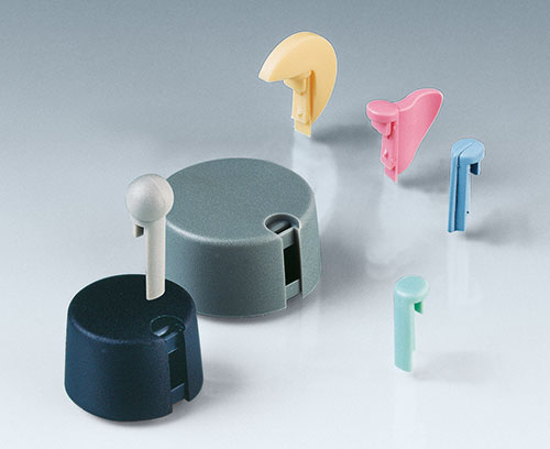
Check out this company OKW that makes cool modular knobs just outside of Paris : https://www.okw.fr/fr/Boutons-de-commande
**************
Working with the array of simple, robust, electronic components (switches, knobs, linear pots, track balls, etc.). Trying to think about how they could be daisy-chained together.


****************
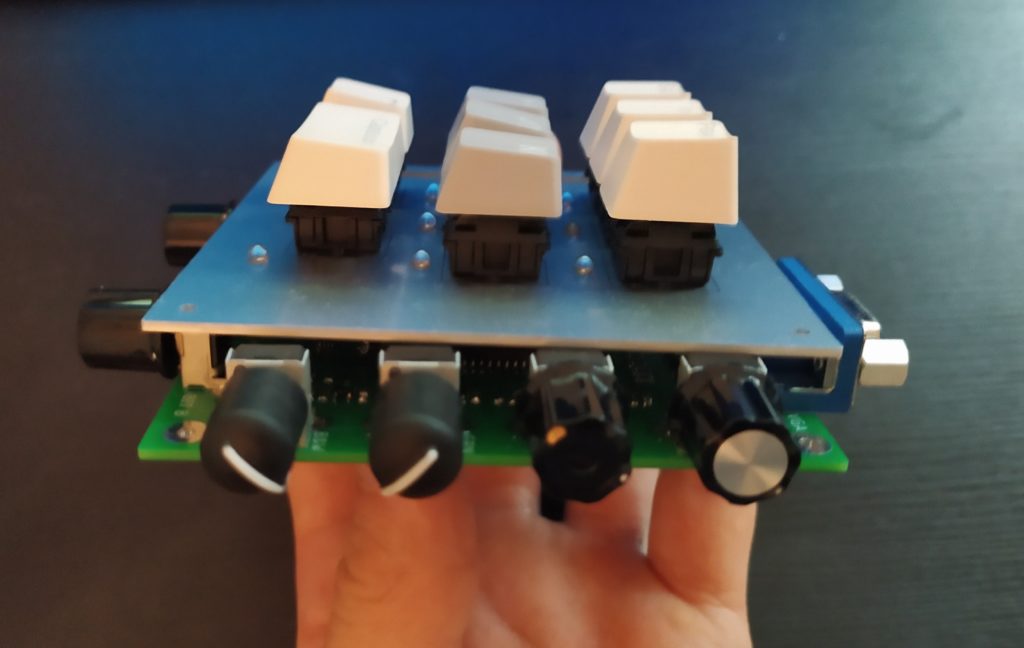
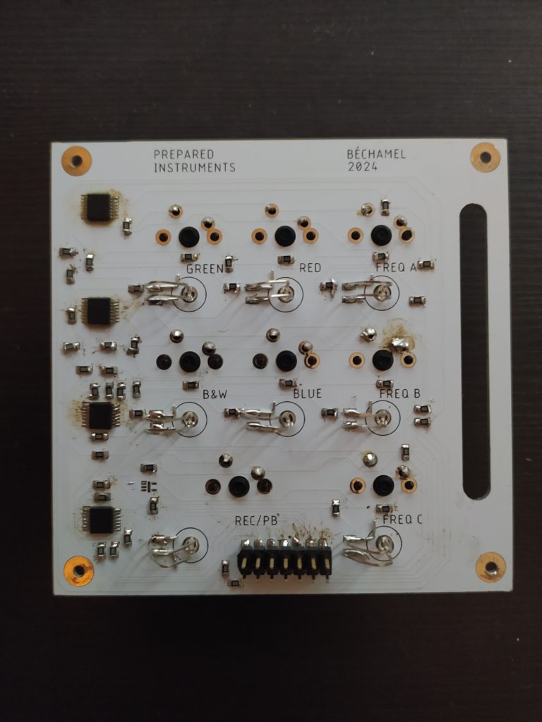
Received and soldrerd PCBs !
- The aluminum layer can be engraved ! I could put “bechamel” on it !
- The standoff holes are too small for standard size.
- The boards are not perfectly the same dimensions.
- Perhaps I should have chosen white for the FR4 board instead of green
- No caps on the keyboard board
- Blurg, soldering components on the aluminum board without a heated plate is near impossible. I could have at least selected bigger format ICs.
- The latched keys which are connected to the output buffer enables aren’t really useful. They should be constantly on as the amp can always be just turned down to turn off the channel.
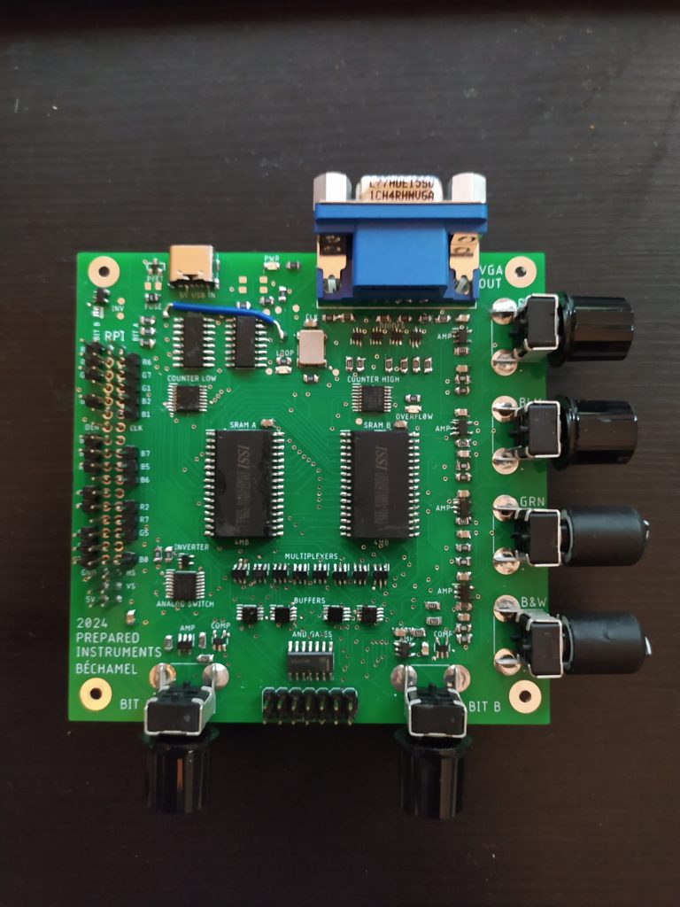
ERRATA MOTHERBOARD :
- From now on I think I will solder with a stencil and an oven, it’s too much work to solder manually.
- The latched keys don’t activate the same channels via buffer that they activate via AND gate to analog switch SEL.
- Also the text BLU, RED etc next to the knobs isn’t really accurate
- Should have VCC and GND on the silkscreen next to keyboard jumper
- Pin 13 and 11 of the 590 should by default be connected together on the next board
- I replaced the caps at the VGA out with 0ohm jumpers because I couldn’t see anything passing through on the oscilloscope
- I should add the turn off switch for rpi
- I am considering getting rid of the integrated rpi, despite its advantages, for a more straightforward HDMI IN or VGA IN. It adds considerable thickness to the board with the bulky 40 pin jumper situation and the fact that it is headless makes debugging a real pain.
ERRATA KEYPAD :
- I’m not sure the idea of using the aluminium sided boards really works, it’s all a bit too risky in terms of short circuits and it’s a real pain to solder (I need a heated plate, a nice microscope, loads of flux and a soldering iron). Fabien’s suggestion is to make the holes larger, so there is little risk of the pins touching the aluminium substrate, and then wiring flexible wire to make the necessary connections. Perhaps add some glue to keep the keys in place and move all the circuitry to the reverse side of the motherboard.
- Fabien had the idea of using the square holes of the mechanical switches possibly to mount them in the metal, perhaps they would even clip into place ?
- I roasted the ICs during soldering I think, the LEDs and JK latches are not working as expected.
- The added height for the two female ribbon cable connectors butting up against each other is insane. If it’s possible to just plug one board directly into the other you can achieve some nice compact sandwich board.
- Once again the 2mm standoff holes are too tiny
- The slot is perfect and the LEDs passing through the holes works as expected (though I should really use insulation on the two legs).
**************
Could I use coils from floppy disk player in a matrix as capacitive touch array ?
Could I make a super low resolution LED monitor to replace the HDMI IN and HDMI OUT DSLR field monitor ? (https://www.amazon.fr/Feelworld-Moniteur-Monitor-1920×1080-Peaking/dp/B07J5C98NW/ref=sr_1_1_sspa?crid=2SJEJTOJ1C6HB&keywords=Cam%C3%A9ra+Moniteur+DSLR&qid=1707557998&s=electronics&sprefix=cam%C3%A9ra+moniteur+dslr+%2Celectronics%2C89&sr=1-1-spons&sp_csd=d2lkZ2V0TmFtZT1zcF9hdGY&psc=1) :

I could also just use the simple rpi 5″ HDMI screen.
Other connection options if I had HDMI out :

Would it be smart to keep a VGA out as a plan B if ever the HDMI stopped working ?
It would be super useful to have a micro usb out to power the portable screen / pico projector. If so not much space left, would need to maybe bring the USB C power cable to the rpi side.
*************
Check out Jim Campbell’s low res display :!


References to reconstructing memories from the mind too !
***************
Setting up another rpi to loop VLC videos. I used primarily this tutorial: https://forums.raspberrypi.com/viewtopic.php?t=17051
First off, I kept the language as english to simplify things (despite having a french keyboard). I believe I did the rpi Lite installation (and then downloaded VLC?) but I’m not 100% sure.
In the place of
nano /home/pi I have my user name :nano /home/marrs
I also needed to go to View > Show Hidden to see the .config file then autostart then autovlc.desktop
nano /home/marrs/films/.config/autostart/autovlc.desktopNOTE : This can’t be a text file, easiest way is to create the file directly in the terminal to avoid any problems as explained here :https://learn.sparkfun.com/tutorials/how-to-run-a-raspberry-pi-program-on-startup/method-2-autostart
I put this in the file (there is nothing else there)
[Desktop Entry]
Type=Application
Exec=vlc --loop --fullscreen /home/marrs/playlist.m3u

Then control+O to save the file
 I put the m3u playlist here : home/marrs/playlist.m3u
# For more options and information see
# http://rpf.io/configtxt
# Some settings may impact device functionality. See link above for details

# uncomment if you get no picture on HDMI for a default "safe" mode
#hdmi_safe=1

# uncomment the following to adjust overscan. Use positive numbers if console
# goes off screen, and negative if there is too much border
#overscan_left=16
#overscan_right=16
#overscan_top=16
#overscan_bottom=16

# uncomment to force a console size. By default it will be display's size minus
# overscan.
#framebuffer_width=1280
#framebuffer_height=720

# uncomment if hdmi display is not detected and composite is being output
#hdmi_force_hotplug=1

# uncomment to force a specific HDMI mode (this will force VGA)
#hdmi_group=1
#hdmi_mode=1

# uncomment to force a HDMI mode rather than DVI. This can make audio work in
# DMT (computer monitor) modes
#hdmi_drive=2

# uncomment to increase signal to HDMI, if you have interference, blanking, or
# no display
#config_hdmi_boost=4

# uncomment for composite PAL
#sdtv_mode=2

#uncomment to overclock the arm. 700 MHz is the default.
#arm_freq=800

# Uncomment some or all of these to enable the optional hardware interfaces
dtparam=i2c_arm=off
#dtparam=i2s=on
dtparam=spi=off

# Uncomment this to enable infrared communication.
#dtoverlay=gpio-ir,gpio_pin=17
#dtoverlay=gpio-ir-tx,gpio_pin=18

# Additional overlays and parameters are documented /boot/overlays/README

# Enable audio (loads snd_bcm2835)
dtparam=audio=on

# Automatically load overlays for detected cameras
camera_auto_detect=1

# Automatically load overlays for detected DSI displays
#display_auto_detect=1

# Enable DRM VC4 V3D driver
#dtoverlay=vc4-kms-v3d
max_framebuffers=2

# Disable compensation for displays with overscan
disable_overscan=1

[cm4]
# Enable host mode on the 2711 built-in XHCI USB controller.
# This line should be removed if the legacy DWC2 controller is required
# (e.g. for USB device mode) or if USB support is not required.
otg_mode=1

[all]

[pi4]
# Run as fast as firmware / board allows
arm_boost=1

[all]

gpio=0-9=a2
gpio=12-17=a2
gpio=20-25=a2
gpio=26-27=a2

dtoverlay=dpi24

enable_dpi_lcd=1
display_default_lcd=1

dpi_group=2
dpi_mode=87

extra_transpose_buffer=2

dpi_output_format=0x7f216
dpi_timings=720 0 40 48 128 720 0 13 3 15 0 0 0 60 0 50000000 1
*************
A new vision for this project : it’s a lo-fi device that takes HDMI and outputs HDMI but allows all kinds of very low res transformations like super low resolution GIFs, and saving every Nth frame of a film.
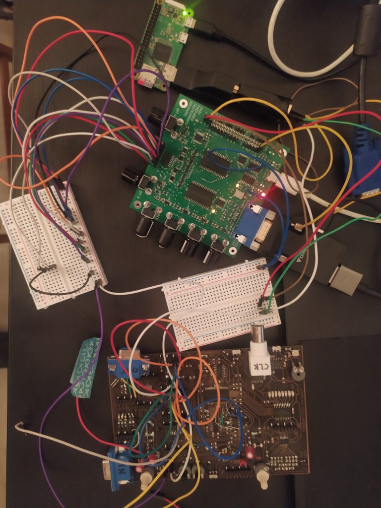
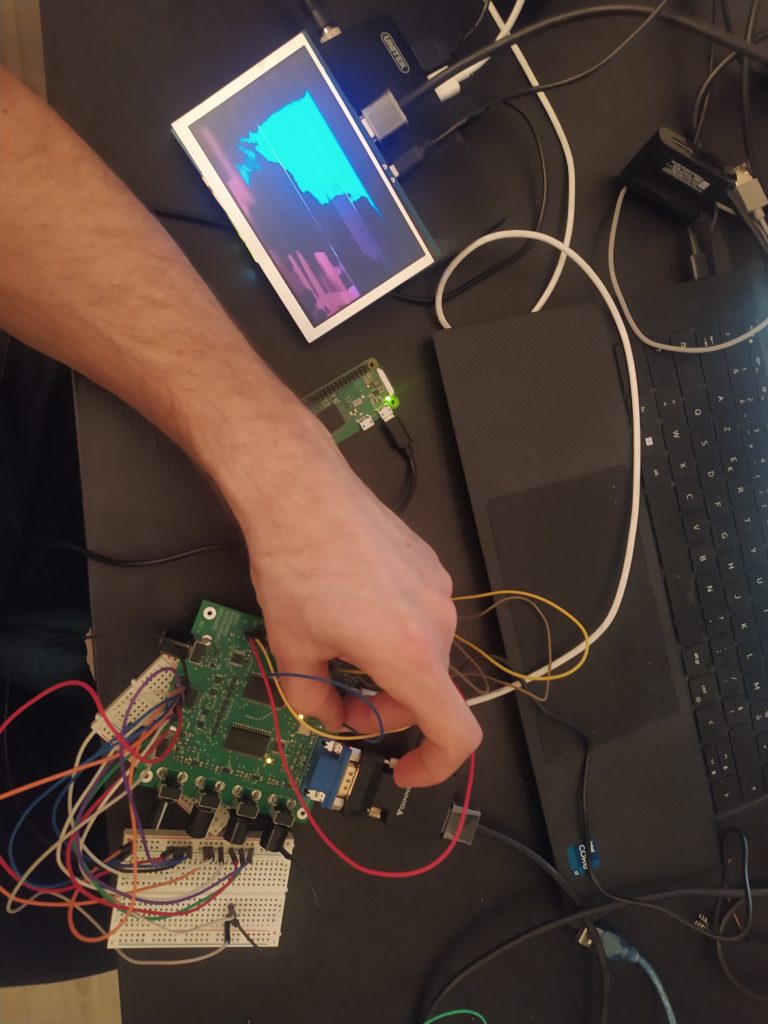
****TESTING ***
- Get sync sorted on this board. **EDIT** Unfortunately taking HSYNC, VSYNC and their inverses, and sending them to the 590 on various pins is not syncing the video. Thinking back, I think I managed this only when I was ANDing a bunch of freq divisions and then inverting the output to record images only every nth frame. *EDIT* OK I’ve got something taking VSYNC as the freq and the AND’ind the outputs to be used to reset the 4040 counters.
- Test the keyboard interface experience. ***EDIT** oof this is painful to do with jumpers and breadboards. Everything seems to be very sensitive to wierdness. It makes me want to eliminate the double board concept and just stick with hard soldered stuff on a single board. In the moments when things were briefly working it was super cool to control things with the keyboard.
- See what other video distortion is possible with the circuit
- I tried out the new HDMI converter, it works well.
- I figured out that you can save a multicolor multichannel image by recording on several channels at once !
- I like the idea of avoiding mission creep – not going into the screen or video codec business but instead staying with the theme of the project : video memory recording and playback.
- I like the idea of emphasizing how little memory there is here (4MB), and how I am trying to use every part of the bison rather than going for more memory.
- the new board should have usb micro female plugs to power an rpi, a VGA to HDMI converter, or the 5″ HDMI screen.
- No more connectors between boards that are mirrored… Thinking of a single-sided board where the buttons relate the the function (latched push button for things that need to be latched like the freq sel) keyboard keys for selecting layers to record to. I thought that having an array of the same button would make things clean but it ends up being confusing what button does what. I like the idiosyncratic and non orthogonal matrix approach.
- Just realized that I only need the single pole analog switch and don’t need the double pole anymore.
- I have higher quality pots I could use for smoother action
Super cool to see everything on the tiny screen actually (but when I plugged in everything from the v synth I think it went above the fuse limit so I’ll have to FIX THIS IN THE NEXT VERSION if I want all to be powered by the board):
 *
*
Trying to make a list of cool new video distortions possible with this board :
- RCK and CLK of 590 could be connected to different frequencies
- could have two different counter pairs for two memories that could be desynchronized
**********
A quick redesign :
- Different components for different functions that they control (flat pots for inputs)
- Added DIP switches to turn on and off diff V SYNC divisions going to 4040 counter reset
- Only two speed buttons now, and they are physically latched
- Nicer quality top facing pots
- HDMI in and out with TI chips
- got rid of some replaceable components
- two micro USB connections to allow for these options :


*****
Trying out some hyper symmetrical design here.
Some considerations :
- Leaving enough room to be able to comfortably twist the knobs
- having mechanic keys close to one another so that they can be easily tapped with adjacent fingers
- associating each key with it’s respective knob spatially and clustering controls that are thematically related (like the dip switch and the two frequency setting pushbuttons which are both temporal)
- components that extend beyond the board on the top and bottom leaving room for hands on the keys and knobs
- Tommy thinks it should be hand held.

And a more controller-like option :
*******
Check out Vincent Rioux’s muq machine and how he show the grid of screen shots :

***
I want to make videos like this guy makes experimental sound sets :

****
I’m going to remake the keyboard board (but on FR4, with connector aligned to motherboard, no latched colors to activate channels) and add the sync lock functionality. This will allow me to finish that project and test it easily.
The videos I have already of the board functioning are cool : diff colors allow for multiple images to share the same frame and be legible. The freeze frame(s) is very cool and being able to freeze different chunks of time I think will add a lot of things to test.
After this board I’ll move back to FPGA as they represent the future of the project I think (also the NO SCHOOL workshop this summer). Before I make I new board I should play more with the FPGA SRAM boards I have already made. Can I , for instance, reproduce the bechamel board with an FPGA? Perhaps it is time to upgrade to an FPGA with more LUTs, even if it is harder to solder in Ball Grid Array packaging (and then why not SRAM in BGA also), and the HDMI helper chips.
The dream would be able to throw 20 of the new boards in the oven and have them all work at the end. I could then send them to friends around the world ! Would be clever to use capacitive touch in this case to avoid needing a physical interface like so : https://github.com/stnolting/captouch.
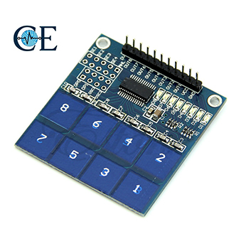
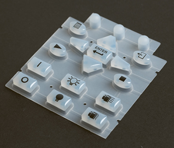
I could also design a silicone ruber keypad for it ! https://en.wikipedia.org/wiki/Silicone_rubber_keypad
Looks like an ESP32 with SD card can generate video as input, that or a rpi integrated into the board.

This might be one of those “already solved” problems which isn’t that much fun to explore…
***
Next steps for the HX8K board :
- FFMPEG can output into monob or monow 1 bit pixel format and different dimensions. Test making a low resolution video and putting it on an SD card and having Arduino read it and transfer it to FPGA on the gameboy console board I made. (This will test if can replace rpi or HDMI IN with SD card in on next board)
- Try again to see if HDMI out is possible with FPGA using the two boards I made to test this. (This will decide if need an HDMI helper chip or not on next board)
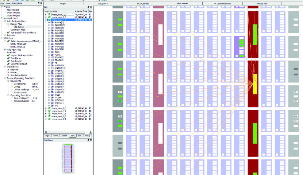
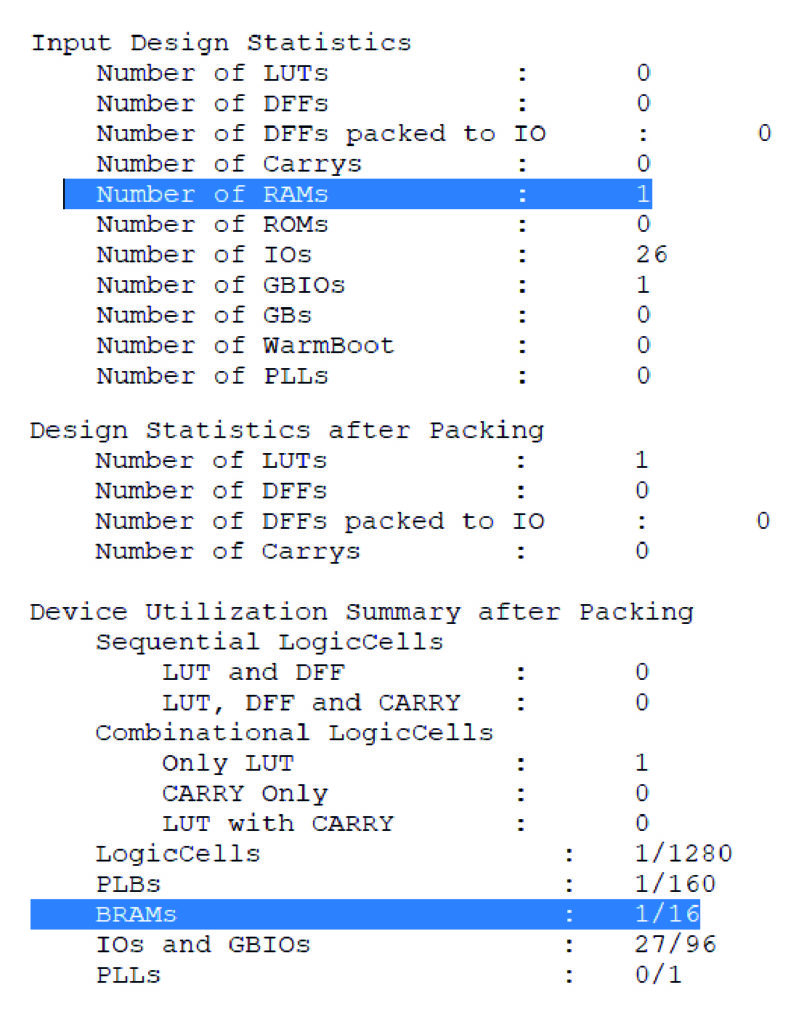
- Try to use internal FPGA BRAM to save a screenshot on the Villette Makerz board. (This will test if need SRAM or not on the next board).
- Replace mechanical keys with capacitive touch so everything is as light as possible.
- Plan to get JLC PCB to assemble it ?
****
New top board, no longer aluminum, no more LEDs, which has the V SYNC ADD circuitry, debounced keys, and a female header to connect directly to the motherboard.
*****
Realized that I haven’t used the BRAM on the FPGA and that I could store low res recordings there. *EDIT* But it’s only 64K in total for the HX1K which is very little space. Probably more useful to store a mini buffer before sending it along to the SRAM. I’ve tried to create BRAM primitives in IceCube but it’s not working so far. This code from TinLethax appears to work in IceCube :
module BRAM(
input R_CLK,
input W_CLK,

input [7:0]BRAM_IN,
output reg [7:0]BRAM_OUT,

input [11:0] BRAM_ADDR_R,
input [11:0] BRAM_ADDR_W,

input B_CE_W,
input B_CE_R);

reg [7:0] mem [3003:0];

always@(posedge R_CLK) begin// reading from RAM sync with system clock
if(!B_CE_R)
    BRAM_OUT <= mem[BRAM_ADDR_R];
end

always@(posedge W_CLK) begin// writing to RAM sync with Slave SPI clock.
if(!B_CE_W)
    mem[BRAM_ADDR_W] <= BRAM_IN;
end

endmodule
This code from the Lattice Memory Guide (file:///C:/Users/jm225306/Downloads/MemoryUsageGuideforiCE40Devices.pdf) also works :
 module ram (din, addr, write_en, clk, dout);// 512x8
parameter addr_width = 9;
parameter data_width = 8;
input [addr_width-1:0] addr;
input [data_width-1:0] din;
input write_en, clk;
output [data_width-1:0] dout;
reg [data_width-1:0] dout; // Register for output.
reg [data_width-1:0] mem [(1<<addr_width)-1:0];

always @(posedge clk)
begin
if (write_en)
mem[(addr)] <= din;
dout = mem[addr]; // Output register controlled by clock.
end
endmodule
After sorting out the parameters BRAM_ADDR_WIDTH and BRAM_DATA_WIDTH, this code also works : https://github.com/Megamemnon/bram/blob/master/bram.v
****
I am swinging back to the SD card and a very simple video codec begin read/or initialized by Arduino and sent along to the FPGA. I think that this could lead to some new kinds of images and animations, and I think it could move away from having a computer generate video which kind of seems like a cop out for an experimental low-fi video device.
I am also swinging back in the direction of mechanical keys and, if I stick with discrete logic chips at least, by extension the two board option. Not having a real physical interface, and replacing with capacitive touch sensing, seems like losing the plot of an instrument like this. However, I am still interested in learning if I can do everything simpler with an FPGA and eventually add cool functionality like digital filtering that is impossible at the moment.
If I could output VGA and HDMI it would be more robust. It would basically have power in and video out only.
So basically, I am imagining a new corrected/optimized version of the bechamel (higher quality pots, streamlining components, etc.) that takes SD video in with an atmega 328p, outputs in HDMI and VGA, but basically has the same look as before with a 4×4 keyboard and motherboard. This new version could conceivably replace logic with an FPGA also but that might be too much of a jump ?
***
Downloaded ffmpeg windows build here : https://www.gyan.dev/ffmpeg/builds/
I tried the following command as a test and it worked nicely :
C:\ffmpeg-2024-02-29-git-4a134eb14a-full_build\bin>ffmpeg -i C:\ffmpeg-2024-02-29-git-4a134eb14a-full_build\bin\input\input.mp4 output.avi
To see the list of formats I could output to I typed in ffmpeg -pix_fmts
There is monow and monob each at 1 bit depth and 1 bits per pixel.
But now I am realizing that I probably want to output just a series of simple bmp images, rather than a video format perhaps.
****
Trying to debug Ice40HXIK HDMI :
- I soldered pin 19 to 5V. No change. I could also solder the HDMI metal case to GND with the jumper.
- It appears that the HDMI signals only appear when some keys are activated, I guess an imperfect connection somewhere ?
- Tested on two diff HDMI screens, not being recognized.
- Looked a the signals with the ‘scope and I’m not seeing differential signals, they are the same signal twice.
- I’m getting various warnings from IceCube when compiling the code (minimalDVID_encoder.vhd : A quick and dirty DVI-D implementation by Author: Mike Field <hamster@snap.net.nz>).
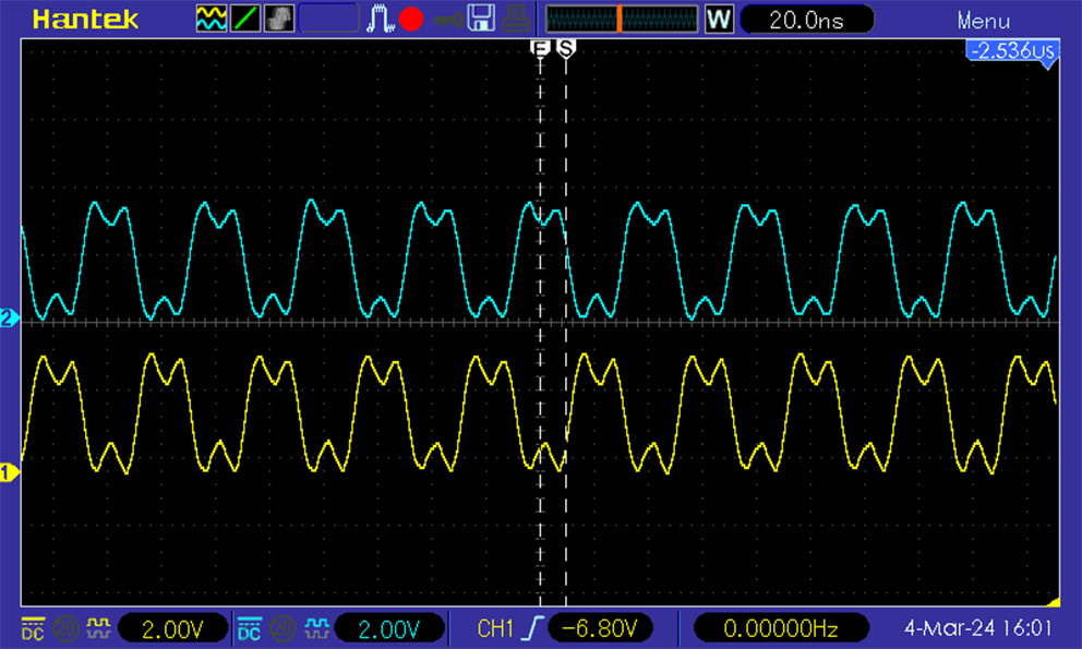
- It is kind of working now after I bitwise (~) inverted the hdmi n pins 🙂
These are the differential signals before inverting properly :

These are the same differential signals after inverting properly :
Here is the code for the Villette Makers Paris Electronic Week board with modifications :
The PCF :
set_io hdmi_p[0] 139 -io_std SB_LVCMOS
set_io hdmi_p[2] 78 -io_std SB_LVCMOS
set_io hdmi_p[1] 80 -io_std SB_LVCMOS
set_io hdmi_p[3] 137 -io_std SB_LVCMOS

set_io hdmi_n[0] 138 -io_std SB_LVCMOS
set_io hdmi_n[2] 79 -io_std SB_LVCMOS
set_io hdmi_n[1] 81 -io_std SB_LVCMOS
set_io hdmi_n[3] 136 -io_std SB_LVCMOS

set_io clk100 49
Mike Field’s minimal HDMI verilog with just the addition of inverted hdmi n pins :
`default_nettype none // disable implicit definitions by Verilog
//-----------------------------------------------------------------
// minimalDVID_encoder.vhd : A quick and dirty DVI-D implementation
//
// Author: Mike Field <hamster@snap.net.nz>
//
// DVI-D uses TMDS as the 'on the wire' protocol, where each 8-bit
// value is mapped to one or two 10-bit symbols, depending on how
// many 1s or 0s have been sent. This makes it a DC balanced protocol,
// as a correctly implemented stream will have (almost) an equal
// number of 1s and 0s.
//
// Because of this implementation quite complex. By restricting the
// symbols to a subset of eight symbols, all of which having have
// five ones (and therefore five zeros) this complexity drops away
// leaving a simple implementation. Combined with a DDR register to
// send the symbols the complexity is kept very low.
//-----------------------------------------------------------------
module top(
clk100, hdmi_p, hdmi_n
);
input clk100;
output [3:0] hdmi_p;
output [3:0] hdmi_n;
// For holding the outward bound TMDS symbols in the slow and fast domain
reg [9:0] c0_symbol; reg [9:0] c0_high_speed;
reg [9:0] c1_symbol; reg [9:0] c1_high_speed;
reg [9:0] c2_symbol; reg [9:0] c2_high_speed;
reg [9:0] clk_high_speed;
reg [1:0] c2_output_bits;
reg [1:0] c1_output_bits;
reg [1:0] c0_output_bits;
reg [1:0] clk_output_bits;
wire clk_x5;
reg [2:0] latch_high_speed = 3'b100; // Controlling the transfers into the high speed domain
wire vsync, hsync;
wire [1:0] syncs; // To glue the HSYNC and VSYNC into the control character
assign syncs = {vsync, hsync};
// video structure constants
parameter hpixels = 800; // horizontal pixels per line
parameter vlines = 525; // vertical lines per frame
parameter hpulse = 96; // hsync pulse length
parameter vpulse = 2; // vsync pulse length
parameter hbp = 144; // end of horizontal back porch (96 + 48)
parameter hfp = 784; // beginning of horizontal front porch (800 - 16)
parameter vbp = 35; // end of vertical back porch (2 + 33)
parameter vfp = 515; // beginning of vertical front porch (525 - 10)
// registers for storing the horizontal & vertical counters
reg [9:0] vc;
reg [9:0] hc;
// generate sync pulses (active high)
assign vsync = (vc < vpulse);
assign hsync = (hc < hpulse);
always @(posedge clk_x5) begin
//-------------------------------------------------------------
// Now take the 10-bit words and take it into the high-speed
// clock domain once every five cycles.
//
// Then send out two bits every clock cycle using DDR output
// registers.
//-------------------------------------------------------------
c0_output_bits <= c0_high_speed[1:0];
c1_output_bits <= c1_high_speed[1:0];
c2_output_bits <= c2_high_speed[1:0];
clk_output_bits <= clk_high_speed[1:0];
if (latch_high_speed[2]) begin // pixel clock 25MHz
c0_high_speed <= c0_symbol;
c1_high_speed <= c1_symbol;
c2_high_speed <= c2_symbol;
clk_high_speed <= 10'b0000011111;
latch_high_speed <= 3'b000;
if (hc < hpixels)
hc <= hc + 1;
else
begin
hc <= 0;
if (vc < vlines)
vc <= vc + 1;
else
vc <= 0;
end
end
else begin
c0_high_speed <= {2'b00, c0_high_speed[9:2]};
c1_high_speed <= {2'b00, c1_high_speed[9:2]};
c2_high_speed <= {2'b00, c2_high_speed[9:2]};
clk_high_speed <= {2'b00, clk_high_speed[9:2]};
latch_high_speed <= latch_high_speed + 1'b1;
end
end
always @(*) // display 100% saturation colourbars
begin
// first check if we're within vertical active video range
if (vc >= vbp && vc < vfp)
begin
// now display different colours every 80 pixels
// while we're within the active horizontal range
// -----------------
// display white bar
if (hc >= hbp && hc < (hbp+80))
begin
c2_symbol = 10'b1011110000; // red
c1_symbol = 10'b1011110000; // green
c0_symbol = 10'b1011110000; // blue
end
// display yellow bar
else if (hc >= (hbp+80) && hc < (hbp+160))
begin
c2_symbol = 10'b1011110000; // red
c1_symbol = 10'b1011110000; // green
c0_symbol = 10'b0111110000; // blue
end
// display cyan bar
else if (hc >= (hbp+160) && hc < (hbp+240))
begin
c2_symbol = 10'b0111110000; // red
c1_symbol = 10'b1011110000; // green
c0_symbol = 10'b1011110000; // blue
end
// display green bar
else if (hc >= (hbp+240) && hc < (hbp+320))
begin
c2_symbol = 10'b0111110000; // red
c1_symbol = 10'b1011110000; // green
c0_symbol = 10'b0111110000; // blue
end
// display magenta bar
else if (hc >= (hbp+320) && hc < (hbp+400))
begin
c2_symbol = 10'b1011110000; // red
c1_symbol = 10'b0111110000; // green
c0_symbol = 10'b1011110000; // blue
end
// display red bar
else if (hc >= (hbp+400) && hc < (hbp+480))
begin
c2_symbol = 10'b1011110000; // red
c1_symbol = 10'b0111110000; // green
c0_symbol = 10'b0111110000; // blue
end
// display blue bar
else if (hc >= (hbp+480) && hc < (hbp+560))
begin
c2_symbol = 10'b0111110000; // red
c1_symbol = 10'b0111110000; // green
c0_symbol = 10'b1011110000; // blue
end
// display black bar
else if (hc >= (hbp+560) && hc < hfp)
begin
c2_symbol = 10'b0111110000; // red
c1_symbol = 10'b0111110000; // green
c0_symbol = 10'b0111110000; // blue
end
// we're outside active horizontal range
else
begin
c2_symbol = 10'b1101010100; // red
c1_symbol = 10'b1101010100; // green
//---------------------------------------------
// Channel 0 carries the blue pixels, and also
// includes the HSYNC and VSYNCs during
// the CTL (blanking) periods.
//---------------------------------------------
case (syncs)
2'b00 : c0_symbol = 10'b1101010100;
2'b01 : c0_symbol = 10'b0010101011;
2'b10 : c0_symbol = 10'b0101010100;
default : c0_symbol = 10'b1010101011;
endcase
end
end
// we're outside active vertical range
else
begin
c2_symbol = 10'b1101010100; // red
c1_symbol = 10'b1101010100; // green
//---------------------------------------------
// Channel 0 carries the blue pixels, and also
// includes the HSYNC and VSYNCs during
// the CTL (blanking) periods.
//---------------------------------------------
case (syncs)
2'b00 : c0_symbol = 10'b1101010100;
2'b01 : c0_symbol = 10'b0010101011;
2'b10 : c0_symbol = 10'b0101010100;
default : c0_symbol = 10'b1010101011;
endcase
end
end
// red N
defparam hdmin2.PIN_TYPE = 6'b010000;
defparam hdmin2.IO_STANDARD = "SB_LVCMOS";
SB_IO hdmin2 (
.PACKAGE_PIN (hdmi_n[2]),
.CLOCK_ENABLE (1'b1),
.OUTPUT_CLK (clk_x5),
.OUTPUT_ENABLE (1'b1),
.D_OUT_0 (~c2_output_bits[1]),
.D_OUT_1 (~c2_output_bits[0])
);
// red P
defparam hdmip2.PIN_TYPE = 6'b010000;
defparam hdmip2.IO_STANDARD = "SB_LVCMOS";
SB_IO hdmip2 (
.PACKAGE_PIN (hdmi_p[2]),
.CLOCK_ENABLE (1'b1),
.OUTPUT_CLK (clk_x5),
.OUTPUT_ENABLE (1'b1),
.D_OUT_0 (c2_output_bits[1]),
.D_OUT_1 (c2_output_bits[0])
);
// green N
defparam hdmin1.PIN_TYPE = 6'b010000;
defparam hdmin1.IO_STANDARD = "SB_LVCMOS";
SB_IO hdmin1 (
.PACKAGE_PIN (hdmi_n[1]),
.CLOCK_ENABLE (1'b1),
.OUTPUT_CLK (clk_x5),
.OUTPUT_ENABLE (1'b1),
.D_OUT_0 (~c1_output_bits[1]),
.D_OUT_1 (~c1_output_bits[0])
);
// green P
defparam hdmip1.PIN_TYPE = 6'b010000;
defparam hdmip1.IO_STANDARD = "SB_LVCMOS";
SB_IO hdmip1 (
.PACKAGE_PIN (hdmi_p[1]),
.CLOCK_ENABLE (1'b1),
.OUTPUT_CLK (clk_x5),
.OUTPUT_ENABLE (1'b1),
.D_OUT_0 (c1_output_bits[1]),
.D_OUT_1 (c1_output_bits[0])
);
// blue N
defparam hdmin0.PIN_TYPE = 6'b010000;
defparam hdmin0.IO_STANDARD = "SB_LVCMOS";
SB_IO hdmin0 (
.PACKAGE_PIN (hdmi_n[0]),
.CLOCK_ENABLE (1'b1),
.OUTPUT_CLK (clk_x5),
.OUTPUT_ENABLE (1'b1),
.D_OUT_0 (~c0_output_bits[1]),
.D_OUT_1 (~c0_output_bits[0])
);
// blue P
defparam hdmip0.PIN_TYPE = 6'b010000;
defparam hdmip0.IO_STANDARD = "SB_LVCMOS";
SB_IO hdmip0 (
.PACKAGE_PIN (hdmi_p[0]),
.CLOCK_ENABLE (1'b1),
.OUTPUT_CLK (clk_x5),
.OUTPUT_ENABLE (1'b1),
.D_OUT_0 (c0_output_bits[1]),
.D_OUT_1 (c0_output_bits[0])
);
// clock N
defparam hdmin3.PIN_TYPE = 6'b010000;
defparam hdmin3.IO_STANDARD = "SB_LVCMOS";
SB_IO hdmin3 (
.PACKAGE_PIN (hdmi_n[3]),
.CLOCK_ENABLE (1'b1),
.OUTPUT_CLK (clk_x5),
.OUTPUT_ENABLE (1'b1),
.D_OUT_0 (~clk_output_bits[1]),
.D_OUT_1 (~clk_output_bits[0])
);
// clock P
defparam hdmip3.PIN_TYPE = 6'b010000;
defparam hdmip3.IO_STANDARD = "SB_LVCMOS";
SB_IO hdmip3 (
.PACKAGE_PIN (hdmi_p[3]),
.CLOCK_ENABLE (1'b1),
.OUTPUT_CLK (clk_x5),
.OUTPUT_ENABLE (1'b1),
.D_OUT_0 (clk_output_bits[1]),
.D_OUT_1 (clk_output_bits[0])
);
// D_OUT_0 and D_OUT_1 swapped?
// https://github.com/YosysHQ/yosys/issues/330
SB_PLL40_PAD #(
.FEEDBACK_PATH ("SIMPLE"),
.DIVR (4'b0000),
.DIVF (7'b0001001),
.DIVQ (3'b011),
.FILTER_RANGE (3'b101)
) uut (
.RESETB (1'b1),
.BYPASS (1'b0),
.PACKAGEPIN (clk100),
.PLLOUTGLOBAL (clk_x5) // DVI clock 125MHz
);
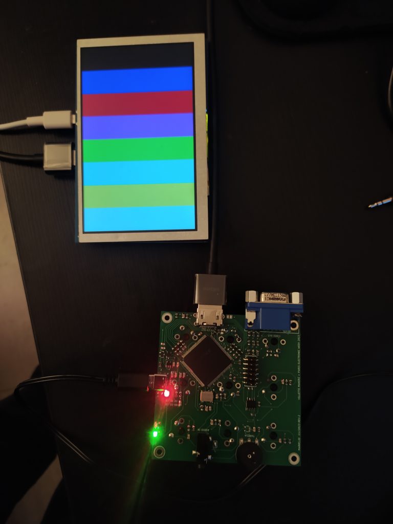
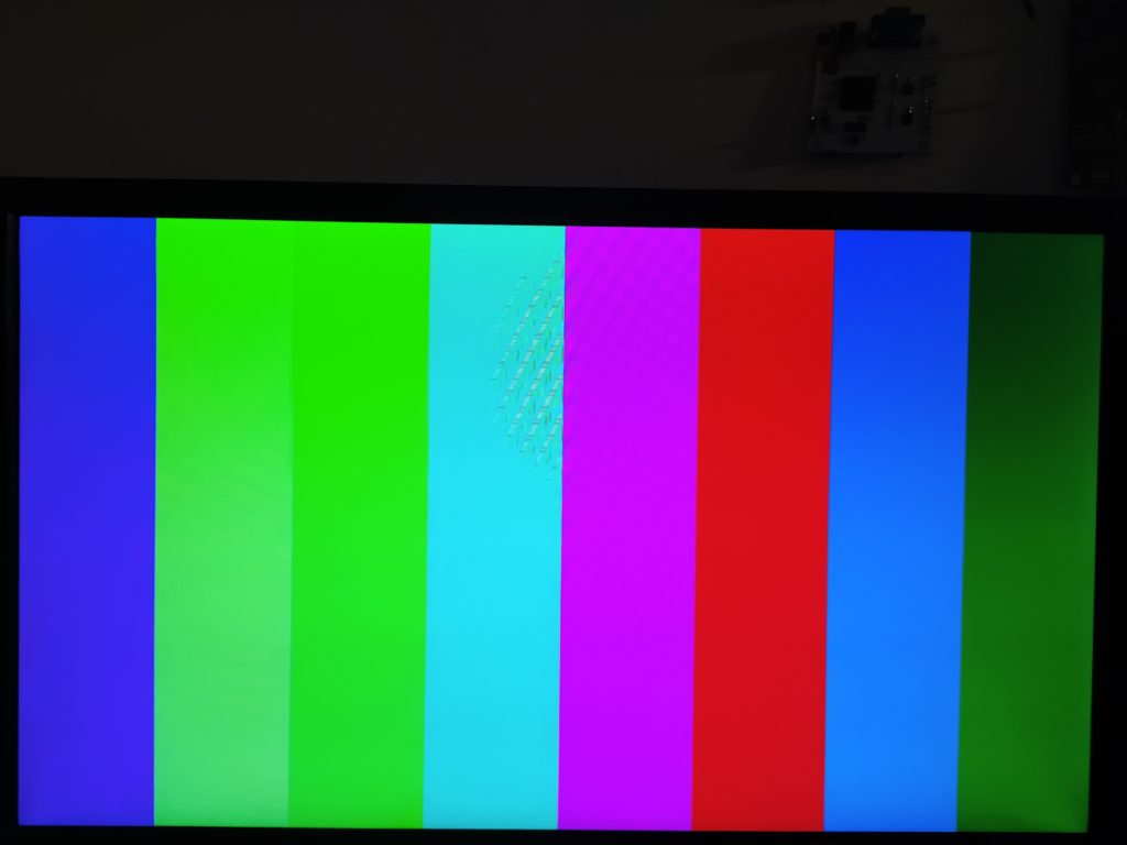
endmoduleProof 🙂 !
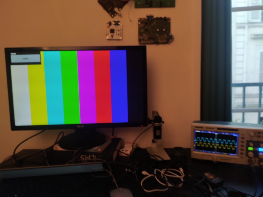
After moving my figure around the board it seemed like the amplifier was creating noise. I removed it and now things seem to work better, however, nothing happens unless I push a button. Could it be because the buttons pass right next to the 100MHz Clock and input pin 49 ? I wonder if I should also make the differential signals closer to the HDMI out. Not sure how I’ll make this work with a noisy board having multiple op amps.
Best thing that has improved reliability has been to push hard on the oscillator one time. It still isn’t solid though, pushing buttons can make it lose connection. I’m going to have to be very careful how I reduce noise in future versions, possibly dividing up the board and having distinct zones. Maybe the double board is more noise resistant also ?
*EDIT* I resoldered the 100MHz clock and now everything is 100% working even when I mash buttons and lay hands on all parts of the board. It also works on the mini HDMI without any issues. YAY !
***
Trying to debug the Ice40HX4K on the gameboy board. I can now upload code, and the clock looks fine, but it’s not outputting anything to the test led pin other than being pulled constantly high.
***
Thought : They (the people who may one day own this kit?) will need an rpi to program the FPGA so I can assume they will have one to produce video. The FPGA would just need to be conected to the programming pins and be able to switch between programming mode and sending pixels. The rpi could actually connect to the same output screen as the video device if there were a switch. It would be more like a marriage of rpi and device, and with a wireless keyboard it could be nice ? At the same time I feel like it complicates the object, and the lo-fi-ness. It also begs the question : why not do everything on the rpi ?
Another thought: if it is HDMI out there are no outputs amps, it’s all digital. I could make a new version without the amps but with the keys. I don’t think it makes sense to make the board with both VGA and HDMI in this case. So, next version could be my first HDMI FPGA synth that replicates the functionality of the bechamel (diff I/O pins as video channels). Not sure if one or two layers.
Might be smart to reuse this board for the NO SCHOOL ? And therefore chose a cheap SRAM. And if this is the case, I can maybe select an inexpensive SRAM (like 1MB or 2MB that runs at 3.3V) and show them how to record incoming video. Perhaps keeping HDMI and VGA out would be smart. Also, perhaps a single sided board too, to minimize cost and weight of this thing. (So basically add small SRAM to the villette makerz 3×3 board and make one key a double if there isn’t enough room). So, forget about SD card video, higher LUT FPGAs and BGA soldering.
- In order to prep for this I could do some more experiments with SRAM FPGA board reproducing béchamel functionality and doing some other low LUT requiring FPGA things.
- I could also program FPGA with rpi to prep
Just one other thought : if FPGA is too challenging for beginners to program, should I make a board with Arduino that commands FPGA to do stuff ?
Another thought : One reason why I have had to keep on ordering new boards is because I always make boards that don’t have every element on it. For example I’ve made boards with SRAM and VGA but not SRAM and HDMI. Perhaps I should include in the following board an atmega 328 and an SD card if I ever get around to doing that in the future. I won’t need to populate it now but basically I can transition into coming up with cool codes and can kind of freeze the board developement.
I can also start by resoldering just the parts of SRAM card that I need to go further in testing bechamel functionality : FPGA, 16MB SRAM, VGA out. This would help understand how important having 16MB of RAM is, because 2MB would be a lot cheaper.
***
Oof, just tried to get the SRAM FPGA back up and running and the complexity of the board, plus the amount of different code versions on the website. The fact that I never sorted out the faulty SRAM pin, the board needing to be bent just so for the counting to start, the hand soldered rpi in colors (can’t remember why I did that), and that the rpi is now restarting itself everytime for some reason. All of it makes me think that I should KEEP THE NEXT BOARD SIMPLE. I also need a proper file structure to store verilog code versions as IceCube loads files and doesn’t just keep the text that you have written in the program.
Tried getting the FTDI board working with HDMI despite not having the differntial resistors. Confirmed that there is differential signals, but it doesn’t appear to work for an HDMI screen.
The mini projector is awesome though :
Also works on the small screen :
![]()
****
A thought : In order to save time, I think I should do the exercise of assuming that I can manage something technically, and doing the thought experiment of trying to understand what would be possible if I can indeed make the thing. For instance, with the HDMI FPGA, I can assume right now that I can do several colors only, but cannot change the intensity of the colors. Having four channels would reaquire having solid colors that overlap.
*****
TLDR : Follow this (https://github.com/anse1/olimex-ice40-notes) but in the place of -w dump put your file name and manually make sure it is exactly 4194304 bytes long (don’t try their -dd code which I can’t get to work).
The long painful version :
Some other research around programming FPGA with rpi :
- https://github.com/squarewavedot/iceprog-rpispi
- https://j-marjanovic.io/lattice-ice40-configuration-using-raspberry-pi.html
- https://github.com/plex1/raspice40
- https://www.olimex.com/wiki/ICE40HX1K-EVB#Get_started_under_Linux IF SCROLL TO THE RPI SECTION
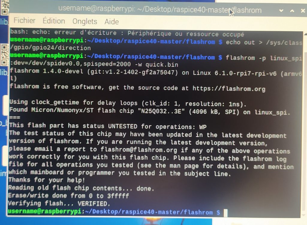
I am following the OLIMEX tutorials because it seems like the best documented and least in progress. Starting with this page (https://github.com/plex1/raspice40) I began by downloading rapice40 and uploading putting an FPGA .bin file I had generated with IceCube2. I activated SSH and SPI on the rpi. I cd’d to the raspice40-master directory and typed sh install.sh. After this I tried to program with program.sh programming_file.bin but it said it didn’t have flashrom. So I started following this website instead (https://www.olimex.com/wiki/ICE40HX1K-EVB#Get_started_under_Linux) and I typed:
git clone https://github.com/flashrom/flashrom.gitThen :
cd flashrommake

sudo CONFIG_ENABLE_LIBPCI_PROGRAMMERS=no CONFIG_ENABLE_LIBUSB0_PROGRAMMERS=no CONFIG_ENABLE_LIBUSB1_PROGRAMMERS=no install
I made the connections between my board and the raspberry pi Zero pins (not the same as the rpi 2+ pins as far as I can see) as per this image :
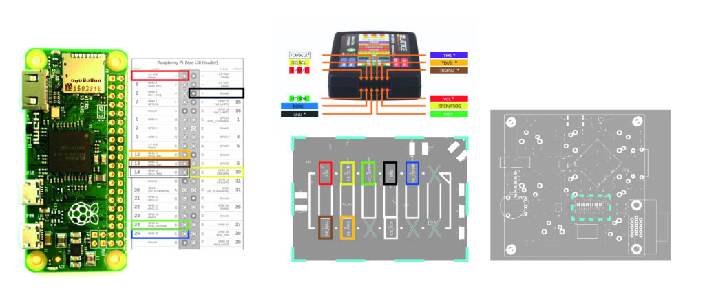
And then :
claim GPIO24 for sysfs-control
echo 24 > /sys/class/gpio/export
Pull GPIO24 low to put the ice40 into reset. The cdone-LED on the board should turn off.
echo out > /sys/class/gpio/gpio24/direction
Read the flash chip at 20MHz (for short cabling)
flashrom -p linux_spi:dev=/dev/spidev0.0,spispeed=20000 -r dump
I tried this but when I looked inside the dump file it was empty.
Simply swap -r for -w to write the dump back
flashrom -p linux_spi:dev=/dev/spidev0.0,spispeed=20000 -w dump
As generated bitstreams are smaller than size of the flash chip, you need to add padding for flashrom to accept them as image. I used the follwing commands to do that:
tr '\0' '\377' < /dev/zero | dd bs=2M count=1 of=image
dd if=my_bitstream conv=notrunc of=image
*EDIT*
This is where I am getting stuck. It can even read the flash chip^on the FPGA board and identify it correctly ! It just keeps on saying that the binary fie is too small to upload.
I can now use the dd command to change the size of the file, and I know the file needs to be 4194304b in size. But it wants that in another number format, but when I try 4194kB it makes it only 31.5 something. I will try asking it for 4M next time and see if that works.
Looking in to padding with dd in different ways to get it up to the required 4194304b size but so far stuck here.
I eventually just used the following command in windows cmd fsutil file createnew <filename> <length> :
fsutil file createnew FPGA.bin 4194304
I then opened this file in hexed.it, and pasted the binary file from IceCube2 into this file (make sure to replace the data and not add it or else you will need to move to the address 4194304 and erase what comes after). I exported it as a bin file, and passed this file (which was precisely the right size) NOT to the program.sh (which I now understand was automating the padding of the input file) but with the following commands in sequence (from https://github.com/anse1/olimex-ice40-notes) :
echo 24 > /sys/class/gpio/export

echo out > /sys/class/gpio/gpio24/direction
flashrom -p linux_spi:dev=/dev/spidev0.0,spispeed=20000 -w FPGA.bin
And I get this success message :
However when I tried it again it could not see the FLASH chip. But to fix this I manually plugged RESET to GND thanks to Fabien’s advice.
*EDIT*
Deassert creset to let the ice40 read the configuration from the bus:
echo in > /sys/class/gpio/gpio24/direction
****
Tried an HDMI splitter and it didn’t split. Also tried to send HDMI to USB C using my adapter, no dice ! I need an HDMI recorder like this :

****
Messed with the HDMI color symbols and can generate many different colors !
// A nice Azure blue for example :
c2_symbol = 10'b1111010000; // red
c1_symbol = 10'b1011110000; // green
c0_symbol = 10'b1011110000; // blue
If you send it something that isn’t balanced colorwise it goes haywire :

c2_symbol = 10'b1111111111; // red
c1_symbol = 10'b1111111111; // green
c0_symbol = 10'b1111111111; // blue

c2_symbol = 10'b0000000000; // red
c1_symbol = 10'b0000000000; // green
c0_symbol = 10'b0000000000; // blue