How can non experts quickly get an idea of the way in which our computers see our raster images?
I have previously focused my energy on how vectors are internally represented because I had the impression that pixel-based rasters were always stored in a predictable top to bottom, left to right arrays in computer memory. However, after a bit of Wikipedia research I discovered that pixels in formats JPEG and PNG are resequenced when they are compressed, downsampled/encoded, or prepared to be sent via a slow internet connection. The last process is called (I think?) Interlacing for JPEGs and Progressive Scanning for PNGs.
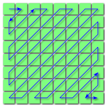
This gif from wikipedia describes the Adam7 algorithm sequencing pixels in a 16×16 bitmap image. (https://en.wikipedia.org/wiki/Interlacing_(bitmaps)) – clearly I want to find something which is dependent on user loaded images and does not transform all images equally.
Apparently when JPEGs are Progressively Scanned the resulting sequence of pixels is not the same irrespective of the image. In spectral selection or successive approximation low-frequency components might be sequenced first before higher-frequency components (citing http://www.libpng.org/pub/png/book/chapter08.html). I.e. the resulting sequence of pixels is not determined by spatial location but by value (color?) of the pixel.
There also appears to be some zig-zag action that takes place in JPEG encoding (https://en.wikipedia.org/wiki/JPEG) :
So, it might be interesting to look at these images in “exploded index” view (displace the pixels in one dimension to show their place in the index). My plan right now is to use Grasshopper to load an image and be able to manipulate the pixels in space based on their place in the input image index. There appear to be a few different Grasshopper plugins for working with images like Shapediver (https://www.food4rhino.com/app/shapediver), Hedgehog(https://www.food4rhino.com/app/hedgehog) and something developed by Professor Andrew Witt at the GSD which I can’t quite track down at the moment.
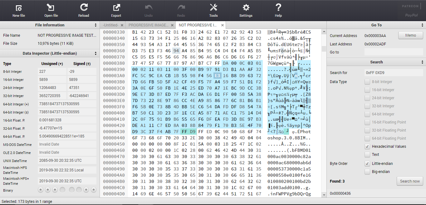
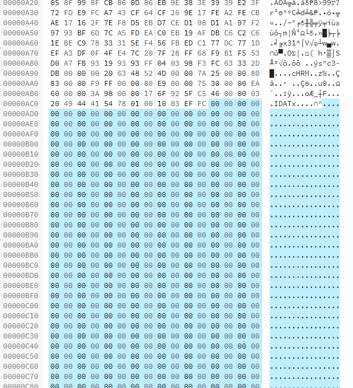
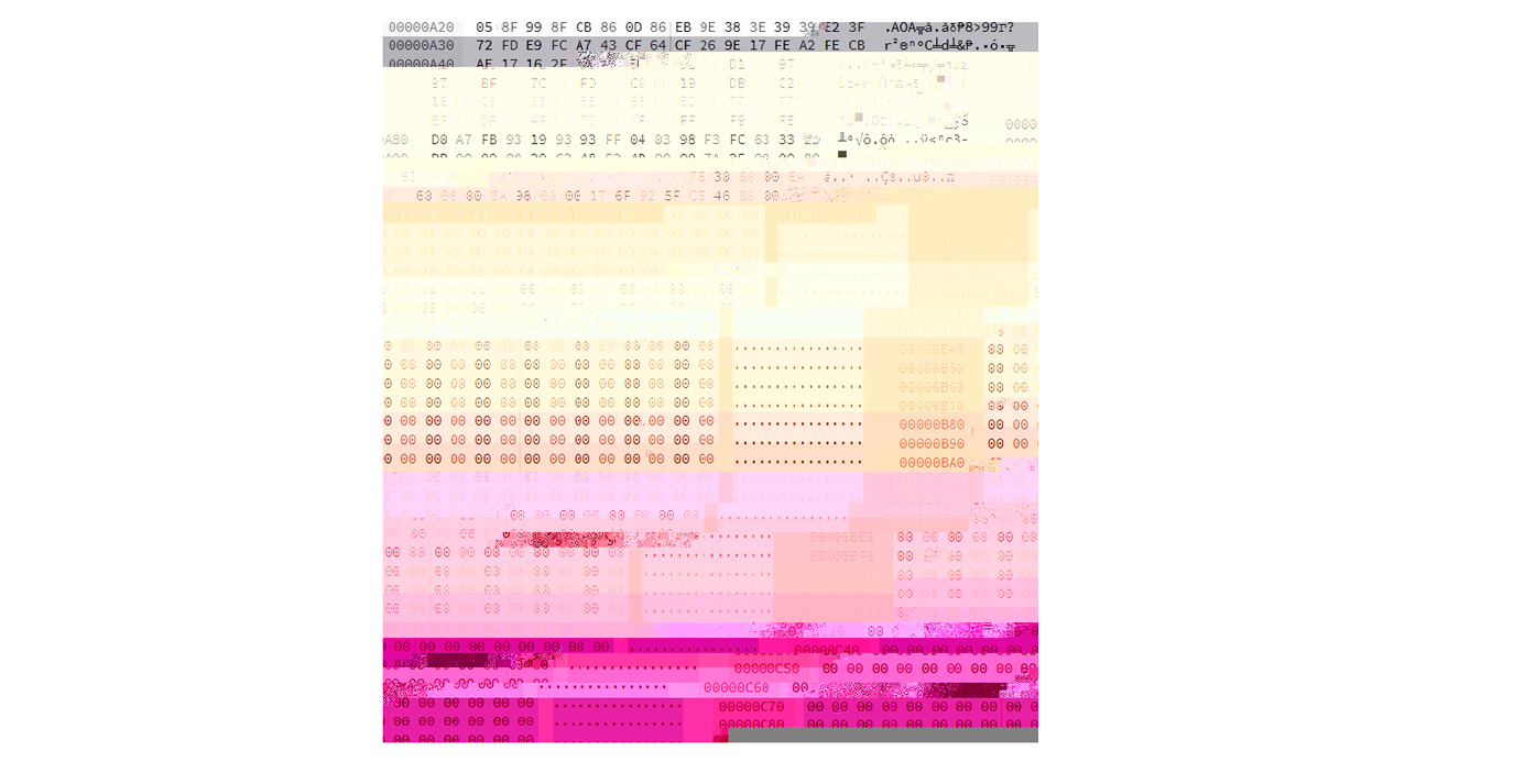
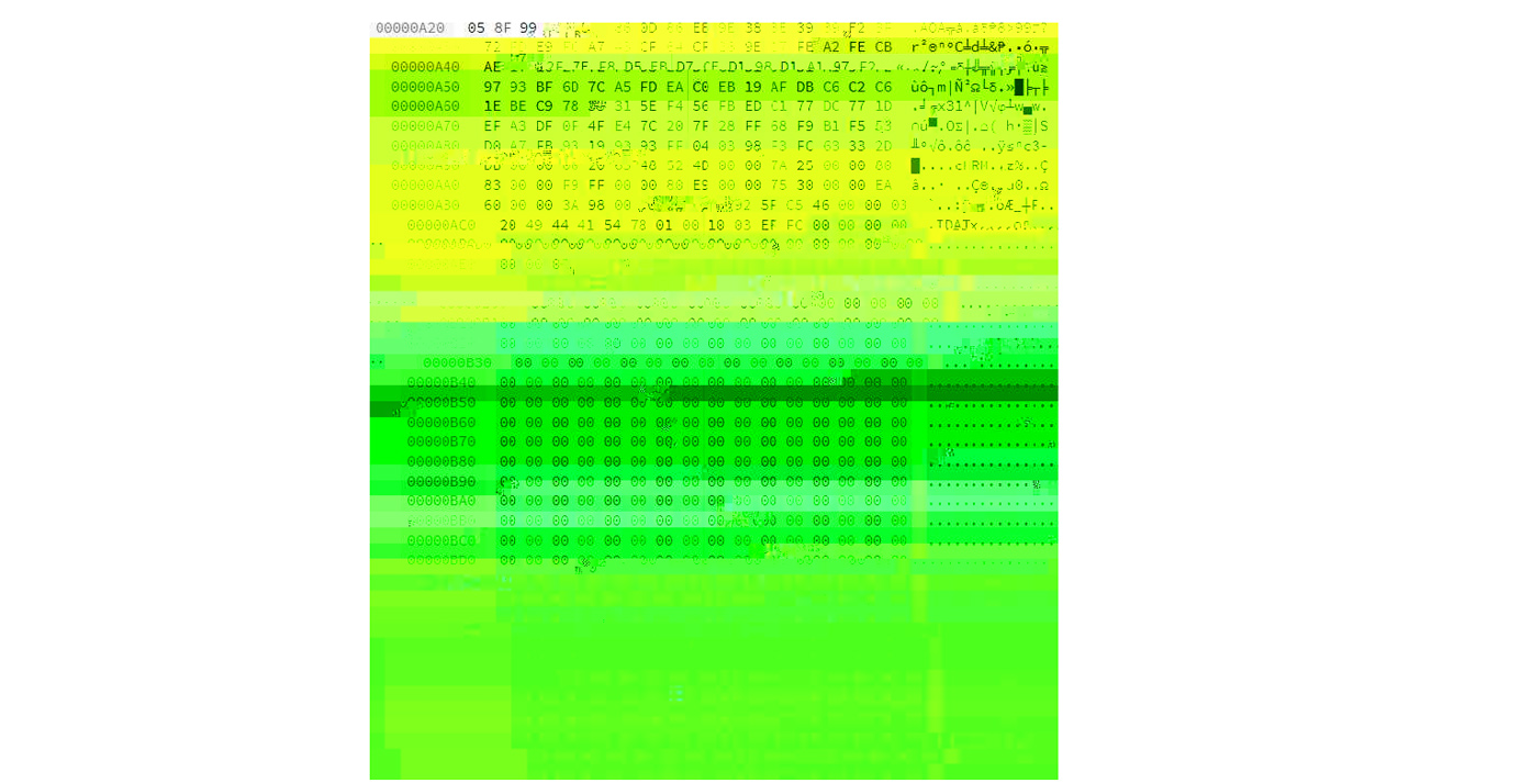
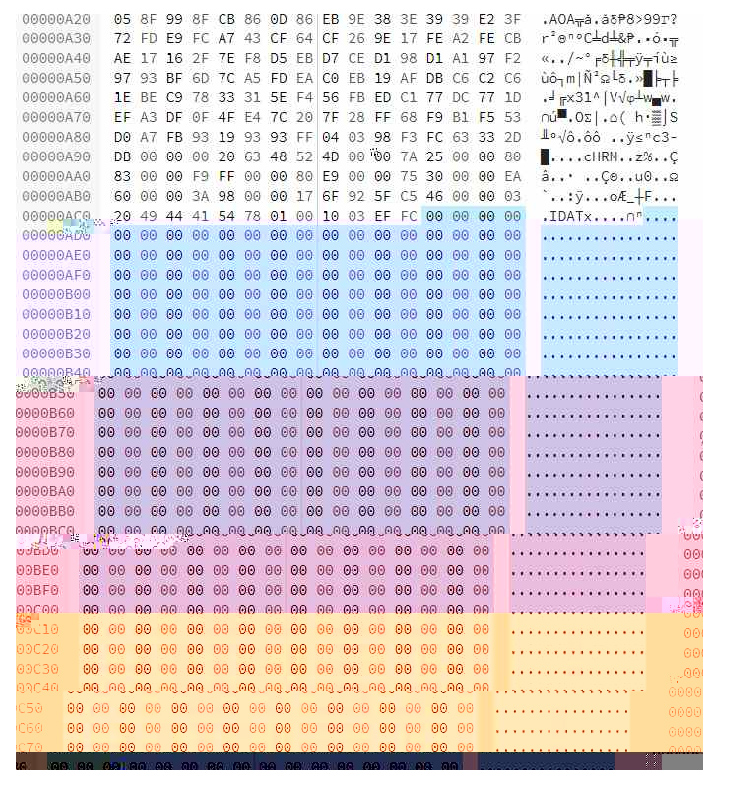
To get the ball rolling though I found a browser-based hex editor called Hexed (https://hexed.it/?hl=en) and began looking at the raw JPEG and PNG data. For PNG the image info is between IDAT and IEND, and there may be several chunks (possibly to make the file more robust in case there is an error in a particular chunk). For JPEG the pixel data is between SOS (0xFF 0xDA) and EOI (0xFF 0xD9). I highlighted one chuck of pixel data in a JPEG image below using Hexed.
I was expecting to find only one image chunk as this image was not saved from Photoshop as “Progressive” but instead I found three chunks. When I save the image as Progressive though I get 9 chunks. Despite saving the image 16×16 with all black pixels I still get a bunch of different hex values for the pixels and I’m not sure why (I thought possibly a CMYK vs RGB situation but a CMYK image at 100% doesn’t make finding a block of pixels with the same value easier for some reason…). So far I am liking PNG files because they are a whole lot smaller.
I just did some tests deleting parts of JPEG and PNG files. I tried removing single bits, and removing chunks. Both resulted in corrupt files which could not be opened.
From https://en.wikipedia.org/wiki/Portable_Network_Graphics:
IHDRmust be the first chunk; it contains (in this order) the image’s width (4 bytes), height (4 bytes), bit depth (1 byte), color type (1 byte), compression method (1 byte), filter method (1 byte), and interlace method (1 byte) (13 data bytes total).[10]PLTEcontains the palette; list of colors.IDATcontains the image, which may be split among multiple IDAT chunks. Such splitting increases filesize slightly, but makes it possible to generate a PNG in a streaming manner. The IDAT chunk contains the actual image data, which is the output stream of the compression algorithm.[11]IENDmarks the image end.
If I change the bit value after IHDR I can mess with the width of the image and this leaves a file which is still readable. When I delete multiples of 8 bits from the file it still appears to load fine also and deletes parts of the image and then adds a single row of random colors.
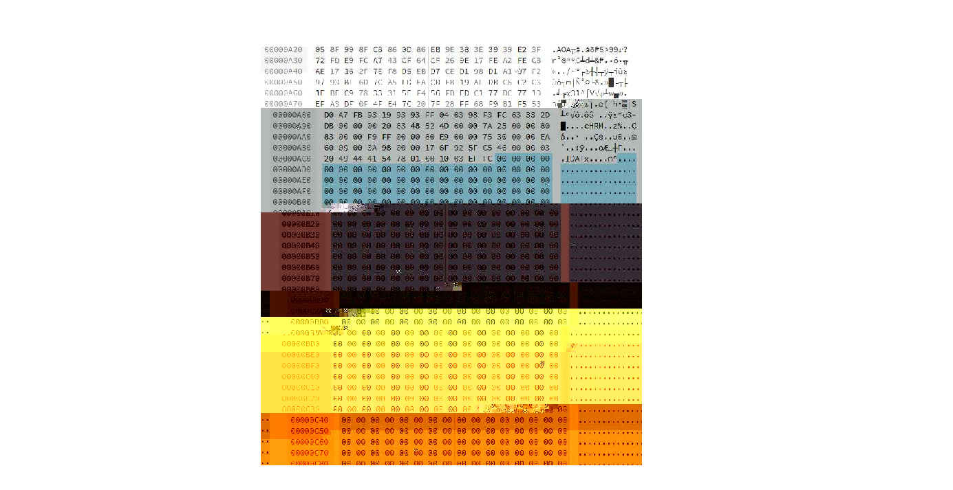
It looks like the images I have made in Photoshop are 16×16 pixels (256 pixels in total) and have a bit depth of 24. There appear to be three Hex pairs of data per pixel (for R,G, and B channels[?]) because there are three times as many hex pairs to describe the image pixels as there are pixels in the image (but also confirmed here: http://www.libpng.org/pub/png/book/chapter08.html#png.ch08.div.4). A Hex pair contains 8 bits worth of data, so 24 bits in total per pixel because that is the bit depth at RGB. Changing the Hex values results in different colors.
Wikipedia says that only the 3 lower bits of each 8 bits of data is used to describe the color…
OK so after reading the PNG specs I am realizing that things are FAR more complicated than I originally assumed. The IDAT pixel data is compressed by the Zlib deflate algorithm and a kind of custom checksum called a CRC is placed at the end. All of this makes it not possible to edit the raw compressed IDAT without first unzipping it and rezipping it with Zlib before reinserting it into the image.
It looks like there is a Python LibZ tool which is described here: https://stackabuse.com/python-zlib-library-tutorial/
There are also people trying to make their own PNGs and documenting their progress on stack exchange:
https://stackoverflow.com/questions/22672112/png-idat-specification?rq=1
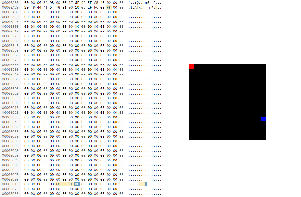
Ah, but I also just realized that if I output a file from Photoshop and select uncompressed it will output a hex stream that more or less directly relates to the pixels in the file.
By making a new image with a single white dot in a field of black I can then move this white dot around by copy pasting FE FE FE (R,G,B) in the sea of 00 00 00. Apparently this doesn’t cause any issues for the CRC. I can also change the color of any individual pixel by finding the triplet of hex pairs that describes that pixel. This appears to work nicely with 16×16 pixel images of black (white not so much?). I can even find the pixels if the image is white:
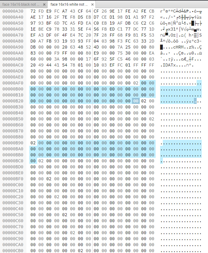
02 appears to mark every new line, I could 48 bytes between each 02 (divided by 3 = 16, the number of pixels in each row of the image).
I have no idea why, but I can’t edit the bottom 1/4 of the image, these two pixels represent the limits of what I can edit.
I failed trying to add an additional row of pixels by changing this value in the IHDR (using Tweak PNG to generate the right CRC once I changed the height of the image in this program) then adding 48 pairs of hex numbers into the IDAT and also changing the CRC at the end of the IDAT using Tweak PNG again.
I did find these nice visuals to describe the PNG files:
https://www.w3.org/TR/2003/REC-PNG-20031110/
***********
After reading a blog post about glitch art and consulting the Image Glitch App page, I decided to give JPEG, TIFF or BMP a try.
I found a nice program which allows for inspection of various kinds of image formats called Exiftool:
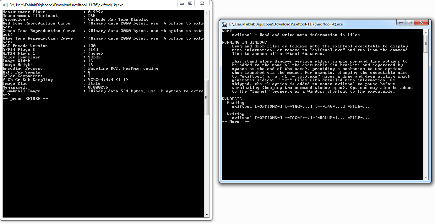
So this program provdes a ton of metadata about a file, but it’s not really optimized for editing pixel info and reloading. Still, this is useful going forward.
Making a B-line directly for image glitching software I found this handsome program Snorpey:
https://snorpey.github.io/jpg-glitch/
It makes very pretty glitches, I wonder if I can find out how it is working under the hood and comandeer it’s behavior to my ends…
I am looking through the source code for the program Glitch Canvas (which seems to be the inspiration for this app) here: https://github.com/snorpey/glitch-canvas
Under Sources, there is a glitch Jscript code which does the glitching I think. Before the image is edited it appears to be first translated into a byteArray, other things are determined beforehand like the start of the image data at SOS. At the heart of the code is a loop which appears to iterate over the bytes in the array. The three glitch parameters, seed, amount and iteration,
Here is the code:
“””
import jpgHeaderLength from ‘./jpgHeaderLength’;
export default function ( byteArray, seed, amount, iterationCount ) {
const headerLength = jpgHeaderLength( byteArray );
const maxIndex = byteArray.length – headerLength – 4;
const amountPercent = amount / 100;
const seedPercent = seed / 100;
for ( var iterationIndex = 0; iterationIndex < iterationCount; iterationIndex++ ) {
const minPixelIndex = ( maxIndex / iterationCount * iterationIndex ) | 0;
const maxPixelIndex = ( maxIndex / iterationCount * ( iterationIndex + 1 ) ) | 0;
const delta = maxPixelIndex – minPixelIndex;
let pixelIndex = ( minPixelIndex + delta * seedPercent ) | 0;
if ( pixelIndex > maxIndex ) {
pixelIndex = maxIndex;
}
const indexInByteArray = ~~( headerLength + pixelIndex );
byteArray[indexInByteArray] = ~~( amountPercent * 256 );
}
return byteArray;
}
“””
So to conclude:
- iteration: changes how many times the main loop runs. This will impact how many bytes are rewritten in the image data portion of the image (smaller the iteration, the more loops and the more bytes transformed).
- seed: changes how many bytes are skipped over each time the loop runs as it moves from the top to the bottom of the pixel data. (larger the parameter, fewer bytes overwritten because more bytes skipped over).
- amount: the value of the new byte which is overwritten each time through the loop. (larger the value, larger the byte value the byte is replaced with).
Clearly I need to learn how the images are prepared as a string of bytes now:
- Images are converted into Base64 (6 bits per digit)
- Then Base64 is converted to an array of bytes (8 bits per digit)
- The bytes are overwritten selectively based on the 3 parameters of the glitching.
- The byte array is recoverted into Base 64.
- The Base 65 is recoverted into an image.
Quick note: I like this stepping effect that is created, this could be useful for showing sequence.
JPEGs seem to be just as super compressed and complex as PNGs. (Though they do appear to load even when defective which is way cooler than PNGs). I’m curious about BMP, it seems simpler…
Nice ASCII patterns from this BMP.

I started moving towards Processing for a moment there, it can easily load and manipulate image data. But I have the feeling it resamples image data similar to Grasshopper. There are several example of Processing scripts which sort pixels by color in an image. They are cool but they don’t appear to relate to the original sequence of pixels. (https://steemit.com/art/@granturismo89/how-to-make-amazing-glitch-art-with-processing-and-asdf-pixel-sort or http://datamoshing.com/tag/processing/)
Now I am looking at a website which outlines a series of artistic strategies for datamoshing:
http://jameshconnolly.com/glitchtalk.html
https://www.glitchet.com/resources
I wonder if I can use my wilderness camera somehow…or hack a digital camera?
RAW files offer the most hackability, they can be saved as a byte array with no header. Different formats start their scanlines in different places on the canvas and sequence RGB differently. Apparently RAW non-interleaved files don’t save pixels sequentially but instead have different layers per color?
compressed files are harder to work with, but they seem the most interesting to visualize because they are going to be messing with the original sequence of bytes and removing data and possibly re sequencing bytes in the process?
She manages to interrupt a Adam7 algorithm to inspect after steps 1-2 (pre-compression) somehow….
JPEG have a Run Length Encoding (RLE) which groups together the same frequencies.
visualizing files by opening them as audio files can quickly show you the overall organization: http://blog.animalswithinanimals.com/2008/09/databending-and-glitch-art-primer-part.html
This author suggests don’t add or subtract bytes to files.
Maybe what I want to be doing is to have a simple processing script that draws pixels from an image file (onto a canvas the size of which I can control) based on a string of bytes (representing the same image) that it reads to get the pixel sequence info.
These are some of the encoding algorithms it would be cool to visualize. I need to find some way to determine the sequence in which these algorithms are processing data:
https://en.wikipedia.org/wiki/Run-length_encoding: runs of data (sequences in which the same data value occurs in many consecutive data elements) are stored as a single data value and count, rather than as the original run. (eg. WWWWWWWWWWWWBWWWWWWWWWWWWBBBWWWWWWWWWWWWWWWWWWWWWWWWBWWWWWWWWWWWWWW becomes: 12W1B12W3B24W1B14W)
https://en.wikipedia.org/wiki/Entropy_encoding: replaces each fixed-length input symbol with a corresponding codeword; the most common symbols use the shortest codes.
https://en.wikipedia.org/wiki/Huffman_coding: Makes a frequency tree of content.
https://en.wikipedia.org/wiki/Discrete_Fourier_transform: a frequency domain representation of the original input sequence.
https://en.wikipedia.org/wiki/DEFLATE
I should check out the program that processes the TTL serial camera images:
https://learn.adafruit.com/ttl-serial-camera?view=all
Page 20 here has a diagram of the hardware compression:
https://www.st.com/content/ccc/resource/technical/document/application_note/group0/a5/9d/22/46/61/6d/4a/ab/DM00356635/files/DM00356635.pdf/jcr:content/translations/en.DM00356635.pdf
**********
New approach: find python code which compresses images and mess with the code to output what I want.
https://github.com/JoshuaEbenezer/huffman_encoding
This code outputs the list of codes and the integer they replace (the length of the code corresponds to the frequency that integer is found in the image).
Here is an output sample:
116 11111111
119 111111101
129 111111100111
132 111111100110
255 111111100101
149 111111100100111
148 111111100100110
142 111111100100101
171 1111111001001001111
173 1111111001001001110
172 1111111001001001101
194 1111111001001001100111
197 11111110010010011001101
190 111111100100100110011001
209 111111100100100110011000111
213 1111111001001001100110001101
224 111111100100100110011000110011
227 1111111001001001100110001100101
233 111111100100100110011000110010011
236 1111111001001001100110001100100101
240 111111100100100110011000110010010011
241 111111100100100110011000110010010010
This diagram explains it all: https://en.wikipedia.org/wiki/Huffman_coding#/media/File:Huffman_coding_visualisation.svg
If I rebuilt the image in grasshopper, and then used the sequence generated by this algorithm, I could alter the grasshopper version of the image based on the algorithm output. I think the effect would not be very interesting though? The other option is to compress the lines of pixels in the image to the same degree they have been compressed by the algorithm.
Here is a nice article breaking down Huffman encoding: https://medium.com/iecse-hashtag/huffman-coding-compression-basics-in-python-6653cdb4c476
I could write a processing code which loads an BMP, goes through each pixel in the image comparing it to the Huffman table (which has pixel value and code to replace it with) and then create a new image which either makes the original pixels longer (adding the same pixel value to the right, thus displacing adjacent pixels and pushing them around the frame) or makes runs of the same pixel shorter based on the length of the encoded Huffman table value. This would result in an image which is compressed based on the frequency of the various pixels.
Processing seems to be good at this, as with the pixel sorting example by Kim Asendorf:
And here is a primer for dealing with images in Processing: https://www.processing.org/tutorials/pixels/
The other approach of sampling a JPEG compression chip could head towards this kind of product: http://pdf.datasheetcatalog.com/datasheets/120/130181_DS.pdf
It has a test mode where the user has access to all internal memory.
From https://cscie12.dce.harvard.edu/lecture_notes/2007-08/20080312/slide19.html:
The GIF to the right is twice the size of the GIF to the left because GIF LZW compresses horizontal pixels of the same color:


Here is a nice article on LZW compression: https://marknelson.us/posts/2011/11/08/lzw-revisited.html . Here is a dictionary or look-up table from Alice and Wonderland that was created by the “greedy” algorithm (which looks for the longest string to replace?),
34830 : 'even\n' 34831 : '\nwith t' 34832 : 'the dr' 34833 : 'ream ' 34834 : ' of Wo' 34835 : 'onderl' 34836 : 'land' 34837 : 'd of l' 34838 : 'long ag' 34839 : 'go:' LZW compression apparently outputs the library along with the compression files. So this could be opened in order to see which sequence of pixels is the most oft repeated. Retro article describing compression techniques: https://www2.cs.duke.edu/courses/spring03/cps296.5/papers/welch_1984_technique_for.pdf This site has really helpful animations for dictionary creation: http://www.data-compression.com/index.shtml. Check this one out explaining Huffman encoding:could try to visualize series of repeated pixel patterns and the "live" processing of these by different algorithms, some greedy others with different priorities? Check out this stuff on frame buffers: This is a CRT screen showing it's memory from wikipedia https://en.wikipedia.org/wiki/Framebuffer:
and this is the color palette for an image:
still from Wikipedia, here is that same image given the wrong color index:
gzthermal is a psuedo heatmap that shows the words that get compressed and those that don't https://encode.su/threads/1889-gzthermal-pseudo-thermal-view-of-Gzip-Deflate-compression-efficiency:
here is a visualization of LZ77 by Canadian programmer Julia Evanshttps://jvns.ca/blog/2013/10/24/day-16-gzip-plus-poetry-equals-awesome/
